New Tribological Ways Part 6 ppt
Bạn đang xem bản rút gọn của tài liệu. Xem và tải ngay bản đầy đủ của tài liệu tại đây (6.13 MB, 35 trang )
Tribology in Water Jet Processes
159
continuous near the nozzle exit but separate and develop into lumps as they travel with the jet.
Shimizu et al. (1998) conducted erosion tests using submerged water jets at injection pressures
ranging from 49 to 118 MPa and cavitation numbers ranging from 0.006 to 0.022. Since the jet
decelerates faster under a submerged environment, material removal by jet impingement is
restricted in the region near the nozzle exit, as compared to jets in air. In addition to high-
speed jet impingement, cavitation erosion is an additional material removal mechanism in the
submerged environment. Cavitating jets are used for cleaning and shot-less peening (Soyama
et al., 2002) in the water jetting industry.
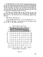
Fig. 6. Cavitating jet at p
i
= 69 MPa and σ = 0.006 (flow direction is from left to right)
4.2 Abrasive jets
The material removal capability of abrasive water jets, in which abrasive particles are added
to the water stream, is much larger than the material removal capability of the pure water
jets. In an abrasive water jet, the stream of the water jet accelerates abrasive particles, which
erode the material. The material removal capability of the water is slight in abrasive water
jet processes. The impact of single solid particles is the basic material removal mechanism of
abrasive water jets. Meng and Ludema (1995) defined four mechanisms by which solid
particles separate material from a target surface, as shown in Figure 7 (Momber and
Kovacevic, 1998). These mechanisms are cutting, fatigue, brittle facture, and melting, which
generally do not work separately, but rather in combination. The importance of these
mechanisms for a particular erosion process depends on several factors, such as the impact
angle, the particle kinematic energy, the particle shape, the target material properties, and
the environmental conditions.
Abrasive water jets can be classified as abrasive injection jets (AIJs) or abrasive suspension
jets (ASJs), as stated earlier. Abrasive injection jets are formed using the nozzle head shown
in Figure 8. A high-speed water jet is injected through the nozzle head. The diameter of the
water jet nozzle is typically 0.2 to 0.4 mm. The high-speed water jet stream creates a
vacuum, which draws abrasive particles into the mixing chamber along with air. The water
jet stream accelerates the abrasive particles and air in the mixing tube, which is typically 0.5
to 1.5 mm in diameter. The cutting width of the AIJs depends on the diameter of the mixing
tube and the standoff distance. For a mixing tube of 1.0 mm in diameter and the standoff
distance of 3 to 5 mm, the cutting width is approximately 1.2 mm.
The three-phase jet flow discharged from the mixing tube consists of abrasive particles,
water, and air. The material removal capability of the AIJ formed by a certain nozzle head
(the dimensions and shape of the nozzle head are fixed) is affected by the pump pressure
and the type and mass flow rate of abrasive. In general, the higher the pump pressure, the
greater the material removal capability. When the abrasive flow rate is relatively small, the
material removal capability increases with the abrasive mass flow rate, because the higher
New Tribological Ways
160
Fig. 7. Mechanisms of material removal by solid particle erosion (Momber and Kovacevic,
1998)
the abrasive mass flow rate, the higher the number of abrasive particles involved in the
cutting processes. On the other hand, when too many abrasive particles are supplied to the
nozzle head, the kinematic energy of the single abrasive particles tends to decrease because
of the limited kinematic energy of the water jet. Thus, there exists an optimum abrasive
mass flow rate. In addition, an uneven abrasive supply to the nozzle head can cause violent
pulsation in AIJs. Shimizu et al. (2009) conducted high-speed observations of AIJs using
high-speed video. Figure 9 shows a series of photographs of an AIJ issuing from the nozzle
head at an injection pressure of 300 MPa and a time averaged abrasive mass flow rate of 600
g/min. The time interval between frames is 12.29 μs, and the flow direction is downward.
Frame numbers are indicated at the top of each photograph. At frame number 1, the jet
spreads radially just downstream of the mixing nozzle exit. As time proceeds, the hump of
the jet develops into a large lump and moves downstream while growing in the stream-wise
direction. As the lump leaves the mixing nozzle exit at frame number 10, another hump of
the jet appears just downstream of the mixing tube exit. Observations of the flow conditions
in the abrasive supply tube just upstream of the mixing chamber of the abrasive nozzle head
were also conducted. Based on image analysis of the video, Shimizu et al. concluded that the
pulsation of an AIJ at a frequency of less than 100 Hz is closely related to the fluctuation of
the abrasive supply.
Wearing of the mixing tube is a serious problem in abrasive water jet machining. In the early
days of abrasive water jet machining, the lifetime of a mixing tube constructed of standard
tungsten carbide was only approximately five hours. However, advances in anti-wear
materials technology have extended the lifetime of the mixing tube to 100 to 150 hours.
In contrast to the abrasive injection jets, abrasive suspension jets are solid-liquid two-phase jet
flows. As shown in Figure 10, abrasive suspension jets are classified into two systems
according to the generation mechanism (Brandt et al., 1994), namely, the bypass system and
the direct pumping system. In the bypass system, part of the water flow is used to draw the
abrasive material out of the storage vessel and to mix it back into the main water flow line. In
the direct pumping system, the pre-mixed slurry charged in a pressure vessel is pressurized by
high-pressure water. An isolator is used to prevent mixing of the slurry and the water.
In the case of the AIJ, the addition of abrasive particles increases the jet diameter and
decreases the jet velocity. The velocity of the ASJ discharged from the nozzle is 0.90 to 0.95
times the theoretical jet velocity calculated by Bernoulli’s equation assuming the loss in the
nozzle to be zero (Shimizu, 1996). Moreover, a compact ASJ can be formed if a suitable
Tribology in Water Jet Processes
161
Fig. 8. Abrasive water jet nozzle head
Fig. 9. Sequential photographs of AIJ,injection pressure: 300 MPa, abrasive mass flow rate:
600 g/min, abrasive: #80 garnet (Shimizu et al., 2009)
nozzle shape is adopted. It is also possible to form an ASJ with a very high abrasive
concentration, such as 50 wt%. Accordingly, the abrasive suspension jet has a greater
capability for drilling and cutting than the abrasive water injection jet. Brandt et al. (1994)
compared the cutting performances of the ASJ and the AIJ under the same hydraulic power
ranges and the same abrasive mass flow rate. They concluded that the ASJ cuts at least twice
as deep as the AIJ at the same hydraulic power. A micro-abrasive suspension system with a
nozzle diameter of 50 μm was also developed (Miller, 2002). Since a cutting width of 60 to 70
μm can be realized using such a system, applications in micro-machining and
semiconductor industries are expected.
In the ASJ system, a convergent nozzle followed by a constant diameter straight passage
(focusing section) of suitable length is generally used. Since abrasive-water slurry flows at
high-speed in the nozzle, slurry erosion of the nozzle is a serious problem. Therefore, in
New Tribological Ways
162
Fig. 10. Abrasive suspension systems (Brandt et al., 1994)
order to reduce nozzle wear, the outlet of the convergent section and the focusing section
are constructed of wear resistance materials, such as sintered diamond. In order to
investigate the effects of the wear of the nozzle focusing section on the material removal
capability of the jet, an experimental nozzle was used to perform drilling tests (Shimizu et
al., 1998). The outlet of the convergent section was constructed of sintered diamond, and the
focusing section was constructed of cemented carbide. The drilling tests were conducted at a
jetting pressure of 11.9 MPa with specimens of stainless steel and #220 aluminum oxide
abrasive. Figure 11 shows the variation of drilling pit depth with standoff distance for a
jetting duration of 60 s. The numbers in the figure are the order of the tests. The cross section
of the nozzle after the drilling tests is shown in Figure 12. The total jetting duration was 780
s. The focusing section (indicated by the arrow) is worn, and the wear of the focusing section
causes a serious reduction in drilling capability, as shown in Figure 11.
Fig. 11. Effect of nozzle wear on pit depth (Shimizu et al., 1998)
Tribology in Water Jet Processes
163
Fig. 12. Nozzle after drilling tests, jetting pressure: 11.9 MPa, abrasive of aluminum oxide
mesh designation of #220 (Shimizu et al., 1998)
5. Conclusion
Friction and wear between the cylinder and the piston of high-pressure pumps used in the
water jetting processes are important problems greatly influence the efficiency, reliability,
and lifetime of the high-pressure pump. Corrosion and erosion in valves and nozzles are
serious problems that affect the reliability of water jetting systems. Erosion by water droplet
impingement is the material removal mechanism of pure water jets, and erosion by solid
particle impingement is the material removal mechanism of abrasive water jet machining.
Knowledge of tribology is indispensable in order to realize more reliable and more efficient
water jet machining systems.
6. References
Brandt, C., Louis, H., Meier, G., & Tebbing, G. (1994), Abrasive Suspension Jets at Working
Pressures up to 200 MPa, Jet Cutting Technology, Allen, N.G. Ed. pp.489-509,
Mechanical Engineering Publications Limited, 0-85298-925-3, London
Faihurst, R.A., Heron, R.A., & Saunders, D.H. (1986), ‘DIAJET’ –A New Abrasive Water Jet
Cutting Technique, Proceedings of 8
th
International Symposium on Jet Cutting
Technology, pp.395-402, 0-947711-17-1, Durham, England, September, 1986, BHRA,
Cranfield
Holmstedt, G. (1999), An Assessment of the Cutting Extinguisher Advantages and
Limitations, Technical Report from the Lund Institute of Technology, Department of Fire
Safty Engineering, Lund University
Ibuki, S., Nakaya, M, & Nishida, N. (1993), Water Jet Technology Handbook, The Water Jet
Technology Society Japan Ed., pp.89-103, Maruzen Co., Ltd., 4-621-03901-6C3550,
Tokyo
Imanaka, O., Fujino, S. Shinohara, K., & Kawate, Y. (1972), Experimental Study of Machining
Characteristics by Liquid Jets of High Power Density up to 10
8
Wcm
-2
, Proceedings of
the first International Symposium on Jet Cutting Technology, pp.G3-25–G3-35,
Coventry, England, April, 1972, BHRA, Cranfield
Inoue, F., Doi, S., Katakura, H., & Ichiryu, K. (2008), Development of water Jet Cutter System
for Disaster Relief, Water Jetting, pp.87-93, BHR Group Limited, 978-1-85598-103-4,
Cranfield
New Tribological Ways
164
Jiang, S., Popescu, R., Mihai, C., & Tan, K. (2005), High Precision and High Power ASJ
Singulations for Semiconductor Manufacturing, Proceedings of 2005 WJTA American
Waterjet Conference, Hashish M. Ed., Papser 1A-3, Houston, Texas, August 2005, The
WaterJet Technology Association, St. Louis, MO
Koerne, P., Hiller, W., & Werth, H. (2002), Design of reliable Pressure Intensifiers for Water-
Jet Cutting at 4 to 7 kbar, Water Jetting, pp.123-132, BHR Group Limited, 1-85598-
042-8, Cranfield
Meng, H.C. & Ludema, K.C. (1995), Wear Models and Predictive Equations: Their Form and
Content, Wear 181-183, pp, 443-457
Miller, D.S. (2002), Micromachining with abrasive waterjets, Water Jetting, pp.59-73, BHR
Group Limited, 1-85598-042-8, Cranfield
Momber, A.W. & Kovacevic, R. (1998), Principles of Abrasive Water Jet Machining, Springer, 3-
540-76239-6, London
Shimizu, S. (1996), Effects of Nozzle Shape on Structure and Drilling Capability of Premixed
Abrasive Water Jets, Jetting Technology, Gee, C. Ed., pp.13-26, Mechanical
Engineering Publications Limited, 1-86058-011-4, London
Shimizu, S., Miyamoto, T., & Aihara, Y. (1998), Structure and Drilling Capability of Abrasive
Water Suspension Jets, Jetting Technology, Louis, H. Ed. pp.109-117, Professional
Engineering Publishing Ltd., 1-86058-140-4, London
Shimizu, S. (2002), High Velocity Water Jets in Air and Submerged Environments,
Proceedings 7
th
Pacific Rim International Conference on Water Jetting Technology, Lee, C-
I., Jeon S., and Song J-J. Eds. pp.37-45, Jejyu, Korea, September 2003, The Korean
Society of Water Jet Technology, Seoul
Shimizu, S. , Ishikawa, T., Saito, A. & Peng, G. (2009), Pulsation of Abrasive Water-Jet,
Proceedings of 2009 American WJTA Conference and Expo, Paper 2-H, Houston
Texas, August 2009, Water Jet Technology Association
Soyama, H. Saito, K. & Saka, M. (2002), Improvement of Fatigue Strength of Aluminum
Alloy by Cavitation Shotless Peening, Transaction of the ASME, Journal of Engineering
Materials Technology, Vol. 124, No.2, pp.135-139.
Springer, G. S. (1976), Erosion by Liquid Impact, Scripta Publishing Co. 0-470-15108-0,
Washington, D.C.
Sugino Machine Ltd. (2007), Catalogue by Sugino Machine Ltd.
Summers, D.A. (1995). Waterjetting Technology, E & FN Spon, 0-419-19660-9, Great Britain
Vijay, M.M. & Foldyna, J. (1994), Ultrasonically Modulated Pulsed Jets: Basic Study, Jet
Cutting Technology, pp.15-35, Mechanical Engineering Publications Limited, 0-
85298-925-3, London
Yan, W. (2007), Recent Development of Pulsed Waterjet Technology Opens New Markets
and Expands Applications, WJTA Jet News, August 2007, WaterJet Technology
Association, St. Louis
Yanaida. K. & Ohashi, A. (1980), Flow Characteristics of Water Jets in Air, Proceedings of 5
th
International Symposium on Jet Cutting Technology, Paper A3, pp.33-44, Hanover,
June 1980, BHRA, Cranfield
9
The Elliptical Elastic-Plastic
Microcontact Analysis
Jung Ching Chung
Department of Aircraft Engineering,
Air Force Institute of Technology
Taiwan ROC
1. Introduction
The elastic-plastic contact of a flat and an asperity which shape is a sphere or an ellipsoid is
a fundamental problem in contact mechanics. It is applicable in tribological problems arising
from the points of contact between two rough surfaces, such as gear teeth, cam and follower
and micro-switches etc. Indeed, numerous works on the contact of rough surfaces were
published so far (see review by Liu et al.). Many of these works are based on modeling the
contact behavior of a single spherical asperity, which is then incorporated in a statistical
model of multiple asperity contact. Based on the Hertz theory, the pioneering work on
contact models of pure elastic sphere was developed by Greenwood and Williamson (GW) .
The GW model used the solution of the frictionless contact of an elastic hemisphere and a
rigid flat to model an entire contacting surface of asperities with a postulated Gaussian
height distribution. The basic GW model had been extended to include such aspects as
curved surfaces (by Greenwood and Tripp), two rough surfaces with misaligned asperities
(by Greenwood and Tripp) and non-uniform radii of curvature of asperity peaks (by
Hisakado). Abbott and Firestone introduced the basic plastic contact model, which was
known as surface micro-geometry model. In this model the contact area of a rough surface is
equal to the geometrical intersection of the original undeformed profile with the flat. Based
on the experimental results, Pullen and Williamson proposed a volume conservation model
for the fully plastic contact of a rough surface.
The works on the above two models are suitable for the pure elastic or pure plastic
deformation of contacting spheres. In order to bridge the two extreme models, elastic and
fully plastic, Chang et al. (CEB model) extended the GW model by developing an elastic-
plastic contact model that incorporated the effect of volume conservation of a sphere tip
above the critical interference. Numerical results obtained from the CEB model are
compared with the other existing models. In the CEB model, there is no transition regime
from the elastic deformation to the fully plastic deformation regime. These deficiencies
triggered several modifications by other researchers. Zhao et al. (the ZMC model) used
mathematical smoothing expressions to incorporate the transition of the contact load and
contact area expression between the elastic and fully plastic deformation regions. Kogut and
Etsion (KE model) performed a finite element analysis on the elastic-plastic contact of a
deformable sphere and a rigid flat by using constitutive laws appropriate to any mode of
deformations. It offered a general dimensionless relation for the contact load, contact area
New Tribological Ways
166
and mean contact pressure as a function of contact interferences. Jackson and Green had
done recently a similar work. In this work, it accounted for geometry and material effects,
which were not accounted for in the KE model. Jackson et al. presented a finite element
model of the residual stresses and strains that were formed after an elastoplastic
hemispherical contact was unloaded. This work also defines an interference at which the
maximum residual stress transitions from a location below the contact region and along the
axis of symmetry to one near to the surface at the edge of the contact radius (within the
pileup).
The aforementioned models deal with rough surfaces with isotropic contacts. However,
rough surface may have asperities with various curvatures that the different ellipticity ratios
of the micro-contacts formed. Bush et al. treated the stochastic contact summits of rough
surfaces to be parabolic ellipsoids and applied the Hertzian solution for their deformations.
McCool took account of the interaction between two neighboring asperities and modelled
the elastic-plastic contact of isotropic and anisotropic solid bodies. Horng extended the CEB
model to consider rough surfaces with elliptic contacts and determined the effects of
effective radius ratio on the microcontact behavior. Jeng and Wang extend the Horng’s
work and the ZMC model to the elliptical contact situation by incorporating the elastic-
plastic deformation effect of the anisotropy of the asperities. Chung and Lin used an elastic-
plastic fractal model for analyzing the elliptic contact of anisotropic rough surfaces.
Buczkowski and Kleiber concentrated their study on building an elasto-plastic statistical
model of rough surfaces for which the joint stiffness could be determined in a general way.
Lin and Lin used 3-D FEM to investigate the contact behavior of a deformable ellipsoid
contacting with a rigid flat in the elastoplastic deformation regime. The above works
provided results for the loaded condition case. Calculations of the stress distribution at the
points of the compression region only under normal load within the ellipse of contact were
dealt with in a number of works. The combined action of normal and tangential loads was
also discussed in some works whose authors examined the stress conditions at points of an
elastic semi-space. However, the above-mentioned works just discussed the distribution of
stresses under the elliptical spot within the elastic deformation regime. The distribution of
stresses within the elastoplastic deformation regime was still omitted. Chung presented a
finite element model (FEM) of the equivalent von-Mises stress and displacements that were
formed for the different ellipticity contact of an ellipsoid with a rigid flat.
2. Important
The present chapter is presented to investigate the contact behavior of a deformable ellipsoid
contacting a rigid flat in the elastoplastic deformation regime. The material is modeled as
elastic perfectly plastic and follows the von-Mises yield criterion. Because of geometrical
symmetry, only one-eighth of an ellipsoid is needed in the present work for finite element
analysis (FEA). Multi-size elements were adopted in the present FEA to significantly save
computational time without losing precision. The inception of the elastoplastic deformation
regime of an ellipsoid is determined using the theoretical model developed for the yielding of
an elliptical contact area. k
e
is defined as the ellipticity of the ellipsoid before contact, so the
contact parameters shown in the elastoplastic deformation regime are evaluated by varying
the k
e
value. If the ellipticity (k) of an elliptical contact area is defined as the length ratio of the
minor-axis to the major-axis, it is asymptotic to the k
e
value when the interference is sufficiently
increased, irrespective of the k
e
value. The ellipticity (k) of an elliptical contact area varies with
The Elliptical Elastic-Plastic Microcontact Analysis
167
the k
e
parameter. The k values evaluated at various dimensionless interferences and two
k
e
values (k
e
=1/2 and k
e
=1/5) are presented. Both interferences, corresponding to the inceptions
of the elastoplastic and fully plastic deformation regimes, are determined as a function of the
ellipticity of the ellipsoid (k
e
).
The work also presents the equivalent von-Mises stress and displacements that are formed
for the different ellipticities. According to the results of Johnson, Sackfield and Hills, the
severest stress always occurs in the z-axis. In this work, we can get the following result: the
smaller the ellipticity of the ellipsoid is, the larger the depth of the first yield point from the
ellipsoid tip happens. The FEM produces contours for the normalized normal and radial
displacement as functions of the different interference depths. The evolution of plastic
region in the asperity tip for a sphere (k
e
=1) and an ellipsoid with different ellipticities
(k
e
=1/2 and k
e
=1/5) is shown with increasing interferences. It is interesting to note the
behavior of the evolution of the plastic region in the ellipsoid tip for different ellipticities, k
e
,
is different. The developments of the plastic region on the contact surface are shown in more
details. When the dimensionless contact pressure is up to 2.5, the uniform contact pressure
distribution is almost prevailing in the entire contact area. It can be observed clearly that the
normalized contact pressure ascends slowly from the center to the edge of the contact area
for a sphere (k
e
=1), almost has uniform distribution prevailing the entire contact area for an
ellipsoid (k
e
=1/2), and descends slowly from the center to the edge of the contact area for an
ellipsoid (k
e
=1/5). The differences in the microcontact parameters such as the contact
pressure, the contact area, and contact load evaluated at various interferences and two k
e
values are investigated.
The elastic-plastic fractal model of the elliptic asperity for analyzing the contact of rough
surfaces is presented. Comparisons between the fractal model and the classical statistical
model are discussed in this work. Four plasticity indices ( 0.5, 1, 2, and 2.5
ψ
=
) for the KE
(Kogut and Etsion) model are chosen. The topothesy (G) and fractal dimension (D) values,
which are corresponding to these four plasticity indices in the present model, will thus be
determined.
3. Theoretical background
In the present chapter, Figure 1 shows that a deformable ellipsoid tip contacts with a rigid
flat. The lengths of the semi-major axis of an ellipsoid and the semi-minor axis are
assumed to be
cR (1 c
≤
<∞) and R , respectively. From the geometrical analysis, the radii
of curvature at the tip of an ellipsoid,
2
1
()
x
RcR= and
1
()
z
RR= , are obtained. the
ellipticity of an ellipsoid is defined as
e
k , and
12
11
(/) 1/ /
ezx
kRR cRcR===. For 1c = ,
1
e
k = , corresponds to the spherical contact; for c →∞, 0
e
k
=
, corresponds to the
cylindrical contact. The simulations by FEM are carried out under the condition of a given
interference
δ
applied to the microcontact formed at the tip of an ellipsoid. Because of
geometrical symmetry, only one-eighth of an ellipsoid volume is needed in the finite
element analysis (see Figure 2). At an interference,
δ
, an elliptical contact area is formed
with a semi-major axis,
a, and a semi-minor axis, b. The length ratio k is here defined as
k=b/a, which is called the ellipticity of this elliptical contact area. The material of this
ellipsoid is modeled as elastic perfectly plastic with identical behavior in tension and
compression.
New Tribological Ways
168
The contact area of an asperity here is elliptical in shape, having two semi-axis lengths, a
and
b (b<a), in the present study. The eccentricity of the contact ellipse (e) is
12
2
2
1
b
e
a
⎛⎞
=−
⎜⎟
⎜⎟
⎝⎠
(1)
Define the C
′
parameter as
()
12
Cab
′
≡ , this parameter has been derived by Johnson [25] as
() {}
12 13
13
1
*
3
()
4
e
FR
Cab Fe
E
⎛⎞
′
==
⎜⎟
⎝⎠
(2)
Where
e
R denotes the effective radius of curvature of an asperity.
[]
12
32 2
1
2
4b a
F( ) E(e) ( ) ( ) ( )
ab
e
eKeKeEe
π
⎧
⎫
⎡⎤
⎪
⎪
⎛⎞ ⎛⎞
=−−
⎢⎥
⎨
⎬
⎜⎟ ⎜⎟
⎝⎠ ⎝⎠
⎢⎥
⎪
⎪
⎣⎦
⎩⎭
(3)
*
E in Eq.(1) denotes the effective Young’s modulus of two solid contact bodies with the
Young’s moduli,
1
E and
2
E , and the Poisson ratios,
1
ν
and
2
ν
, respectively. It is stated as
22
12
*
12
11 1
EE
E
ν
ν
−−
=+
(4)
Where
F denotes the normal load of an asperity at the Hertz contact area. K(e) and E(e) in the
formula of
1
()Fe denote the complete first and second elliptic integrals of argument (e),
respectively. They are expressed by Johnson as
π 2
22
0
dθ
K(e)
1esinθ
=
−
∫
(5)
π 2
22
0
E(e) 1 e sin θ dθ=−
∫
(6)
The onset of the plastic yield of ductile materials usually occurs when the von Mises’ shear
strain-energy criterion reaches
2
*'2
2
()
3
Y
Jk
== (7)
Where
*
2
J
is the maximum value of the second invariant of the deviator stress tensor (
2
J ) at
yielding and
'
k is the material yield stress in simple shear. The second invariant of the
deviator stress tensor can be written as:
()
()()
22
2
2122331
1
6
J
σσ σσ σσ
⎡
⎤
=−+−+−
⎢
⎥
⎣
⎦
(8)
The Elliptical Elastic-Plastic Microcontact Analysis
169
Where
1
σ
,
2
σ
, and
3
σ
are the three principal stresses. In the study of Sackfield and Hills,
the stress distributions formed by the Hertz contact pressure acting on an elliptical contact
surface were developed and it was shown that the severest stress always occurs on the z
axis, and the maximum value of
2
J should occur at a certain point on this axis. The position
of the point
*
Z can be determined from the solution of the following equation:
*
2
0
ZZ
J
Z
=
∂
=
∂
(9)
Where
/Zza=
is the dimensionless z-coordinate, and
*
Z
denotes the
Z parameter when
2
J has the maximum value at yielding.
The interference at the initial point of yielding is known as the critical interference,
y
δ
,
which is derived analytically by using the von Mises yield criterion and given by Lin and
Lin as
() ()
1
2
1
1
3
2
3
1
*2
9
2
16
y
y
e
F
kFe Ke
ER
δ
π
−
⎛⎞
⎜⎟
=⎡⎤
⎣⎦
⎜⎟
⎝⎠
(10)
Where
()
()
32
3
2
*
1
*2
,,
6
e
y
R
FFeKkZY
E
π
ν
⎡
⎤
=⎡⎤
⎣⎦
⎣
⎦
(11)
The corresponding critical contact area is expressed as
()
2
2
3
3
1
*
3
4
ye
c
FR
aFe
E
π
⎛⎞
=
⎡⎤
⎜⎟
⎣
⎦
⎜⎟
⎝⎠
(12)
Where
Y is the yielding stress of the ellipsoid material.
*
(,, )Kk Z
ν
denotes the factor of the
maximum contact pressure arising at yielding. This factor is expressed as a function of the
ellipticity of the contact area,
k , and the Poisson ratio of a material,
ν
.
*
Z is the location of
first yielding point on z-coordinate. The derivation of
*
(,, )Kk Z
ν
is shown in Lin and Lin’s
work. Ellipsoid deforms elastically as / 1
y
δ
δ
<
. When / 1
y
δ
δ
> the ellipsoid is in the
elastoplastic deformation.
b
a
Before
deformation
After
deformation
Rigid Flat
Deformable
ellipsoid
y
X
Z
δ
Fig. 1. The contact schematic diagram of a rigid flat with an ellipsoid.
New Tribological Ways
170
4. Finite element model
In the present work, a commercial ANSYS-8.0 software package is applied to determine the
elastoplastic regime arising at a deformable ellipsoid in contact with a rigid flat (see figure
2). There are two ways to simulate the contact problem. The first applies a force to the rigid
body and then computes the resulting displacement. The second applies a displacement and
then computes the resulting contact force. The present finite element solution is generated
under a given interference
δ
applied to the contact area formed at the tip of an ellipsoid.
This method is used because the resulting solution converges more rapidly than the former.
In order to satisfy the geometrically symmetric condition and to assure that the nodes on the
boundary of
0y = are far away from the contact area, the selection of one-eighth of the
ellipsoidal volume as the simulation domain is made. Several option settings of ANSYS-8.0
software package have been made to reduce error in finite element calculations. The option
of a static large displacement is adopted for the calculations in the elastoplastic and fully
plastic regimes. The choice of the displacement style is based on the stress-strain (or load-
displacement) behavior exhibited in each of these two deformation regimes. The ellipsoid is
assumed to be an elastic-perfectly plastic material with identical behavior in tension and
compression. This assumption was also made in the studies of Kogut and Etsion, and
Jackson and Green. Frictionless and standard contact was also assumed as in their numerical
simulations.
To increase the accuracy and efficiency of computation, one-eighth of an ellipsoid is used.
Several mesh refinements have been performed to reduce the error in calculating von-Mises
stress. For this investigation ANSYS element types 10-node, tetrahedron SOLID 92 element
is selected for this nonlinear contact problem. Three sizes, 0.0005
R, 0.0008R, and 0.001R (R:
the semi-minor radius of ellipsoid), are the smallest element sides in the contact region set
for ellipsoids with
e
k =1, 1/2 and 1/5, respectively. In the present numerical model, the
mesh size was refined according to its distance from the
y-axis and the contact area of an
ellipsoid. The fine mesh size of the volume element near the tip of the ellipsoid is varied in
order to allow the ellipsoid’s curvature to be captured and accurately simulated during
deformations (see Figure 2). As to the region far away from the
y-axis and the contact area,
different coarser element size can be given in order to save computational time without
sacrificing the precision of the solutions. As shown in Figure 2, constraints in the
x
directions and
z direction are applied to the nodes on the x=0 plane and z=0 plane,
respectively, while a constraint in
y direction is applied on the base (the y=0 plane). The
boundary condition may be valid for the modeling of asperity contacts for two reasons: (1)
the asperities are actually connected to a much larger bulk material at the base and will be
significantly restrained there, and (2) since the high stress region occurs near the contact, the
boundary condition at the base of the ellipsoid will not greatly effect the solution because of
Saint Venant’s Principle.
In order to validate the model, mesh convergence must be satisfied. The mesh density is
iteratively increased until the contact force and contact area differed by less than 1%
between iterations. In the finite element analyses, the resulting meshes consist of at least
124572,125714, and 222913 elements correspond to ellipsoids with
e
k =1, 1/2 and 1/5,
respectively. These three node numbers are sufficient to obtain the numerical solutions with
a high precision, compared with the theoretical solutions developed for the elastic
deformation region. It is found that an excessive increase in the number of elements does
The Elliptical Elastic-Plastic Microcontact Analysis
171
not bring a significant improvement in the solution precision. The “contact wizard” in the
software determines the relationship of the contact pair. The rigid flat is set as “Target”, and
the deformable ellipsoid is set as “Contact”.
In addition to mesh convergence, the present work also compares well with the Hertz
solution at interference below the critical interference. The numerical solutions for several
contact parameters with different
k
e
values (k
e
=1, k
e
=1/2 and k
e
=1/5) are listed in Table 1.
The error between the theoretical and numerical solutions for all contact parameters is
found to be always less than 1.5%. In the present study, the FKN (contact stiffness) value is
varied in a range of 10 to 100 in the finite element analyses. Since precise solutions in all
contact parameters are ensured, the accuracy of the solutions in the elastoplastic and fully
plastic deformation regimes obtained by the present mesh scheme is ascertainable.
Furthermore, because
1
e
k
=
represents a spherical contact, the present work compares with
the results which are obtained by Jackson and Green and shows good agreement.
Since this contact problem is nonlinear and highly difficult to converge. An iterative scheme
is used to solve for the solution, the minimum and maximum substeps are set in the range of
10 to 2000 such that ( /
y
δ
δ
)/(substep number) has a value varying in the range of 0.05~0.2.
This is done to ensure the load increment is sufficiently small at each load step, thus
improving the convergence behavior and minimizing the Newton-Raphson equilibrium
iterations required.
Fig. 2. The finite element analysis and the meshed model for simulations.
New Tribological Ways
172
k
e
=1 k
e
=1/2 k
e
=1/5
Hertz
solution
FEA
solution
Hertz
solution
FEA
solution
Hertz
solution
FEA
solution
1
yy
δ
δ
1 0.99 1.85 1.83 3.21 3.19
eqv
SY
1 1 1 0.99 1 0.99
max
PY
1.61 1.63 1.65 1.62 1.73 1.74
Table 1. The comparison of numerical evaluated results at the critical interference with the
theoretical solutions in the elastic deformation case
5. Results and discussion
The results are presented for a range of interferences,
δ
, which are normalized by each
corresponding critical interference,
y
δ
, from 1 to 120 for a sphere, 1 to 100 for an ellipsoid
(
e
k =1/2) and 1 to 70 for an ellipsoid (
e
k =1/5). The factor of the maximum contact pressure
arising at yielding criterion,
K, as shown in Eq. 7, is expressed as a function of
()
*
,,
f
kZ
ν
.
The used material properties are for a steel material and present as 0.3
ν
=
, E=2.07x10
11
Pa,
Y=7x10
8
Pa, and R=10
-4
m. These material properties allow for effective modeling of all the
elastoplastic contact regimes in the FEM simulation. The force convergence tolerance is 0.01
for the nonlinear solutions. Once the mesh is generated, computation takes from 1 hour for
small interference to 50 hours for large interference by using an IBM p690 computer.
Figure 3-a shows the first yield point in the ellipsoid tip for (a) sphere (
e
k =1), (b) ellipsoid
(
e
k =1/2), (c) ellipsoid (
e
k =1/5) while the deformation equals to each critical interference
y
δ
. It is found that the first yield point happens in the larger depth from the ellipsoid tip for
the smaller ellipticity of an ellipsoid, where the depth of the first yielding point is calculated
as the distance between the top of the tip of an ellipsoid and the locations of the first
yielding point. The smaller the ellipticity of the ellipsoid is, the larger the depth from the
ellipsoid tip happens. While the first yielding depth values are normalized by the depth of
ellipticity
e
k =1, the values corresponding to
e
k =1,
e
k =1/2,
e
k =1/5 are 1, 1.5 and 1.8,
respectively.
Figure 3-b shows the comparisons of the critical interference
y
δ
and the location of the first
yielding point with the ellipticity of a contact area
k. The critical interference,
y
δ
, is
significantly increased when the ellipticity of a contact area,
k, is reduced. The depth of the
first yielding point is deeper as the ellipticity of a contact area becomes smaller. The
ellipticity of a contact area, k, is actually governed by the ellipticity of the ellipsoid. The
ellipticities of a contact area formed at the yielding point for
e
k =1,
e
k =1/2,
e
k =1/5 are k=1,
1/2.5 and 1/7.95 respectively. If the ellipticity of a contact area is smaller, it will correspond
to the smaller ellipticity of an ellipsoid. The described phenomena can be seen on figure 3-a.
Figure 4 presents the evolution of the plastic region inside the ellipsoid tip for (a) sphere
(
e
k =1),(b) ellipsoid (
e
k =1/2) and (c) ellipsoid (
e
k =1/5) while
1/ 30
y
δ
δ
≤
≤
. Connecting
the nodes with the equivalent von-Mises stress equals yield stress,
Y, which is recorded by
the commercial finite element program ANSYS 8.0, draws the elastic-plastic boundary line.
The Elliptical Elastic-Plastic Microcontact Analysis
173
The behavior of the evolution of the plastic region in the ellipsoid tip for different
ellipticities of an ellipsoid,
k
e
, is different. The development of plastic region on the contact
surface is shown in more details in figure 7.
The evolution of the plastic region inside the ellipsoid tip at larger normalized interference,
40 / 120
y
δ
δ
≤≤
, is shown in figure 5. As the interference increases above
/80
y
δ
δ
=
, the
normal penetration of the plastic region is coincided at about 0.805x10
-4
m as shown in figure
5(a) for a sphere tip (
e
k =1). The above phenomena doesn’t happen in the ellipsoid tip for
ellipticity
e
k =1/2 and
e
k =1/5 at larger interference. The shapes of the plastic region in the
ellipsoid tip for different ellipticities are also different.
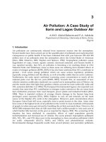
Figure. 6 presents the three dimension contour plots of the equivalent von-Mises stress on
the contact surface for (a) sphere (
e
k =1), (b) ellipsoid (
e
k =1/2) and (c) ellipsoid (
e
k =1/5) at
interference / 10
y
δ
δ
=
. At this interference the plastic region reaches the contact surface for
both a sphere and an ellipsoid, which is shown in more details in figure 7. At this point an
elastic core remains locked between the plastic region and the surface for a sphere (
e
k =1)
and an ellipsoid (
e
k =1/2). It is interesting to note that the center of contact surface for an
ellipsoid (
e
k =1/5) has reached the plastic deformation. The plastic region reaches on both of
the center area and an elliptical annular area on the contact surface for an ellipsoid
(
e
k =1/5). The evolution of the plastic region on the contact surface will behave in a different
way for a sphere and both for an ellipsoid tip. At / 10
y
δ
δ
=
, the boundary of the plastic
region that reaches the contact surface, which is obtained from curve fitting of the finite
element analysis numerical results is plotted as figure 7. The lengths of semi-minor contact
axis that are normalized by the critical contact radius of a sphere are about 2.4, 3.2 and 4.4
for the sphere (
e
k =1), ellipsoid (
e
k =1/2) and ellipsoid (
e
k =1/5), respectively. The lengths
of semi-major contact axis that are normalized by the critical contact radius of a sphere are
about 2.4, 6.8 and 23.5 for the sphere (
e
k =1), ellipsoid (
e
k =1/2) and ellipsoid (
e
k =1/5),
respectively. The curve fitting length on semi-minor contact axis compared to the curve
fitting length on semi-major contact axis is 1/2.13 and 1/5.34 for the ellipsoid (
e
k =1/2) and
ellipsoid (
e
k =1/5), respectively. The above comparison values for the ellipsoid (
e
k =1/2)
and ellipsoid (
e
k =1/5) aren’t equal to the ellipticity of an ellipsoid.
Figure 8 presents the evolution of the plastic region on the contact surface for a sphere
(
e
k =1) while 10 / 120
y
δ
δ
≤
≤ . The boundary of the plastic region on the contact surface
obtained from curve fitting of the finite element analysis numerical results of nodes is
plotted as figure 8. At about / 6
y
δ
δ
=
an annular plastic region first reaches the contact
surface of a sphere. It is clear to see that an elastic core is locked by the annular plastic
region. As the interference increases, the elastic core gradually shrinks and the annular
plastic region will increase both to the center and outer line of the contact area. Finally, the
elastic core disappears and the plastic region will dominate the most part of the contact area
except for the outer annular area surrounded by the elastic region as shown in figure 8. The
same conclusions have been obtained in the Kogut and Etsion’s studies and are also seen by
Jackson and Green.
Figure 9 presents the evolution of the plastic region on the contact surface of an ellipsoid
(
e
k =1/2) for increasing interference values up to / 90
y
δ
δ
=
. Up to / 10
y
δ
δ
=
the elastic
region dominate the contact surface. At / 10
y
δ
δ
=
the plastic region first reaches the
contact surface and forms an annular plastic region as shown in Figure 6 and figure 9. For
10 / 30
y
δ
δ
≤≤, the annular plastic region disappears dramatically and an elliptical plastic
New Tribological Ways
174
region appears on the center of contact surface. As the interference increases thereafter, the
plastic region expands from center toward the edge of the contact surface. Even at this
interference / 90
y
δ
δ
=
, the plastic region still doesn’t coincide with the boundary edge of
the contact area. But as figure 15(b) shows, the P/Y value is asymptotic to a constant value
at this interference
/ 100
y
δ
δ
=
. Obviously, the interference
/90
y
δ
δ
=
is near the inception
of the fully plastic deformation for
e
k =1/2.
Figure 10 presents the evolution of the plastic region on the contact surface of an ellipsoid
(
e
k =1/5) for increasing interference values up to / 70
y
δ
δ
=
. Up to / 10
y
δ
δ
=
the elastic
region dominates the contact surface. At / 10
y
δ
δ
=
the plastic region first reaches the
contact surface and forms an annular plastic region as shown in figure 6 and figure 10. In
addition to the annular plastic region, the center of the contact surface also forms a plastic
subregion. For 10 / 30
y
δ
δ
≤
≤ the annular plastic region disappears dramatically and an
elliptical plastic region on the center of contact surface extends the original dominated area.
As the interference increases thereafter, the plastic region expands from center toward the
edge of the contact surface. Even at interference / 70
y
δ
δ
=
, the plastic region still doesn’t
coincide with the boundary edge of the contact area. It can be seen the plastic region extends
toward the direction of the major contact axis as the interference increases. But as figure
15(c) shows, the P/Y value is asymptotic to a constant value at this interference / 70
y
δ
δ
= .
Obviously, the interference / 70
y
δ
δ
=
is near the inception of the fully plastic deformation
for
e
k =1/5.
The normal and radial surface displacements of the nodes on the ellipsoid surface are
monitored in order to investigate the deformation of an ellipsoid. As shown in figure 11~14
the normal and radial directions (including semi-major and semi-minor contact axis)
correspond to the y- and x-, z-axis, respectively. figure 11 and 12 show the surface
displacement,
Uy/
1
y
δ
, in the normal direction for the sphere (
e
k
=1), ellipsoid (
e
k
=1/2) and
ellipsoid (
e
k =1/5) vs. the normalized semi-major axis and semi-minor axis. These plots
show the evolution of the surface normal deformation with increasing normalized
interferences, /
y
δ
δ
. As expected, the normal deformation on contact surface increases with
increasing the normalized interference depth. The boundary between the contact region and
the free surface boundary of the ellipsoid can be seen on the line edge in the plots. The slope
of the normal displacement on the semi-minor axis is larger than the slope on the semi-
major axis. As figure 11 and 12 show, both of the slopes of the normal displacement on the
major and minor axis directions for different ellipticities satisfy: (
k
e
=1) > (k
e
=1/2) > (k
e
=1/5).
The slope near the center and edge of contact surface becomes flat. Figure 13 and 14 show
the surface displacement,
U
x
/
1
y
δ
, in the x radial direction vs. the normalized semi-major
axis and the surface displacement,
U
z
/
1
y
δ
vs. the semi-minor axis for the sphere (k
e
=1),
ellipsoid (
k
e
=1/2) and ellipsoid (k
e
=1/5). In the smaller interference depths, the surface
displaces radially in mostly the negative direction for a sphere and an ellipsoid. The
ellipsoid has the same compression behavior like a sphere. In other word, their contact areas
are smaller than the geometrical intersection of the original undeformed profile with the flat
in the smaller interference depths. This is because at the smaller normalized interferences,
most of the materials in the sphere and ellipsoid are deforming elastically and are allowed
to compress. As the interference is larger and significantly increases past the critical
deformation, the material of the contact region displaces outward into the positive x
The Elliptical Elastic-Plastic Microcontact Analysis
175
direction and negative z direction. It can be seen in figure 14 that the radial displacement
isn’t positive until the normalized interference, / 90
y
δ
δ
=
, for a sphere, / 50
y
δ
δ
= for an
ellipsoid (
k
e
=1/2) and past / 50
y
δ
δ
=
for an ellipsoid (k
e
=1/5). This bulginess occurs
because the yielding material flows plastically and abides by the outlying material of the
contact area. As shown in figure 14, the normalized radial displacement,
U
x
/
1
y
δ
, become
flat near the edge of the semi-major axis of contact area for an ellipsoid (
k
e
=1/5). When
compared the boundary of plastic contact area in figure 10, their locations of semi-major
contact axis are the same.
Figure 15 presents the normalized contact pressure,
P/Y, profile vs the normalized semi-
major contact axis,
a/a
c1
, and semi-minor contact axis, b/a
c1
, for (a) sphere (
e
k =1) at
/120
y
δ
δ
= (b) ellipsoid (
e
k =1/2) at / 100
y
δ
δ
=
, (c) ellipsoid (
e
k =1/5) at / 70
y
δ
δ
= .
When the normalized interferences,
/
y
δ
δ
, equal to 120, 100 and 70, for (a) sphere (k
e
=1), (b)
ellipsoid (
k
e
=1/2) and ellipsoid (k
e
=1/5), respectively, the uniform contact pressure
distribution is almost prevailing in the entire contact area, in which the dimensionless
contact pressure is up to 2.5. The determination of the inception of the fully plastic
deformation regime is based on the observed phenomenon that the normalized contact
pressure and the normalized equivalent von-Mises stresses formed at the contact area have
a uniform distribution. If interference is increased further, these uniform normalized contact
pressures are found to be unchanged. It can be observed clearly that the normalized contact
pressure ascends slowly from the center to the edge of the contact area for a sphere (
e
k =1),
the normalized contact pressure almost has a uniform distribution prevailing the entire
contact area for an ellipsoid (
e
k =1/2), and the normalized contact pressure descends slowly
from the center to the edge of the contact area for an ellipsoid (
e
k =1/5).
Figure 16 shows the variations of the contact-area ellipticity (
k ) in the elastoplastic
deformation regime with the ellipticity of ellipsoid (
e
k ) and the dimensionless interference,
/
y
δ
δ
. The radii of curvature at the tip of the ellipsoid,
1x
R and
1
y
R , are varied with the
contact deformation. The effect of changing the radii of curvature due to contact
deformations has been included in the evaluation of the
k value. Data marked by the “∆”
and “□” symbols is obtained by assuming
1/2
e
k = and 1/5
e
k = , respectively.
Both data sets show that the ellipticity of contact area,
k , is increased by increasing the
dimensionless interference ( /
y
δ
δ
). The data is asymptotic to a constant value equal to the
e
k value associated with it if /
y
δ
δ
is sufficiently large. It should be mentioned that the
ellipticity of the contact area in the elastic deformation regime is always a constant value,
which is equal to the datum shown in Fig. 16 at /
y
δ
δ
=1. Therefore, the k value of an
elliptical contact area is a variable when operating in the elastoplastic deformation regime.
The dimensionless contact areas (
*
A ) in the elastoplastic deformation regime varying with
the dimensionless interference ( /
s
y
δ
δ
) and the ellipticity of the ellipsoid (
e
k ) are shown in
figure 17. The data for each
e
k value can be expressed in a linear form in the log
*
A -log
(/
s
y
δ
δ
) plot. With the same dimensionless interference /
s
y
δ
δ
, the dimensionless contact
area (
*
A ) is lowered by decreasing the ellipticity of the ellipsoid (
e
k ).
Figure 18 shows for the dimensionless contact load (
*
F ) results needed in the applications
of different interferences ( /
s
y
δ
δ
) and ellipticity values of an ellipsoid (
e
k ). Each of these
curves shows a nonlinear relationship between
*
F and /
s
y
δ
δ
. However, the effect of
e
k on
*
F is exactly opposite to that shown in the dimensionless contact area.
New Tribological Ways
176
Kogut and Etsion used the plasticity index
(
)
12
ys
ψδσ
−
= in the evaluations of the
deformations arising at the contacts of rough surfaces, where
s
σ
denotes standard deviation
of asperity heights. However, this plasticity index doesn’t appear in the fractal analyses. In
the Chung and Lin’s study, four plasticity indices ( 0.5, 1, 2, and 2.5
ψ
=
) for the KE model
are chosen. The dimensionless topothesy,
G , and fractal dimension, D, values applied are
thus needed to determine on the base of these four plasticity indices. The plasticity index
introduced by Greenwood and Williamson can be further expressed as
()
12
ys
ψδσ
−
= =
()
()
12
12
ys
δσ σσ
−
−
. In the study of Chung and Lin,
(
)
12
y
δσ
−
is given as
12
12
*
()
()2
y
ec
E
Q
KH R a
δ
σπ
γ
σ
−
−
⎛⎞
⎛⎞
⎛⎞
=
⎜⎟
⎜⎟
⎜⎟
⎜⎟
⎜⎟
′
⎝⎠
⎝⎠
⎝⎠
=
12
*
1
()
2
()
ec
E
Q
KH
Ra
π
γ
−
⎛⎞
⎛⎞
⎜⎟
⎜⎟
⎜⎟
′
⎝⎠
⎝⎠
. In the study of McCool,
the relationship between
σ
and
s
σ
is given as:
2
4
2
3.717 10
1
()
s
R
σ
σ
ησ
−
×
⎛⎞
=−
⎜⎟
⎝⎠
, where the
R
η
σ
values corresponding to 0.5, 1, 2, and 2.5
ψ
=
are 0.0302, 0.0414, 0.0541, and 0.0601,
respectively. Therefore,
0.5
s
ψ
σ
σ
=
⎛⎞
=
⎜⎟
⎝⎠
0.7697,
1
s
ψ
σ
σ
=
⎛⎞
=
⎜⎟
⎝⎠
0.8849,
2.0
s
ψ
σ
σ
=
⎛⎞
=
⎜⎟
⎝⎠
0.9343,
2.5
s
ψ
σ
σ
=
⎛⎞
=
⎜⎟
⎝⎠
0.9472. By the expression
(
)
()
12
12
ys
ψδσ σσ
−
−
= , the
(
)
12
y
δσ
−
values
corresponding to
0.5, 1, 2, and 2.5
ψ
=
are, 0.5699, 1.063, 2.069 and 2.5687, respectively. The
G and D values corresponding to these four
ψ
values are thus shown in figure 19. In figure
19, the ellipticity 1k
=
. The results of the dimensionless contact load predicted by the
Chung and Lin’s model are quite close to those predicted by the KE model, irrespective of
the plasticity index values.
6. Conclusions
The work presents a finite element model (FEM) of the equivalent von-Mises stress and
displacements that are formed for an elastoplastic ellipsoid is loaded
. The material is
modeled as elastic perfectly plastic and follows the von-Mises yield criterion. One-eighth of
an ellipsoid in contact with a rigid flat is used to calculate the von-Mises stresses and
deformations. A three-dimensional, 10-node, tetrahedron SOLID 92 element was selected for
the nonlinear contact problem. Three sizes, 0.0005R, 0.0008R, and 0.001R (R: the semi-minor
radius of ellipsoid), are the smallest element sides in the contact region set for a sphere with
e
k =1 and ellipsoids with
e
k =1/2 and 1/5, respectively
The FEM produce the evolution contour plots of the von-Mises stress with the different
interferences. It is found that the first yield point happens in the larger depth from the
ellipsoid tip for the smaller ellipticity of an ellipsoid. The smaller the ellipticity of the
ellipsoid is, the larger the depth from the ellipsoid tip happens. While the first yielding
depth values are normalized by the depth of an ellipticity
e
k =1, the values corresponding to
e
k =1,
e
k =1/2,
e
k =1/5 are 1, 1.5 and 1.8, respectively.
The Elliptical Elastic-Plastic Microcontact Analysis
177
At a normalized interference, / 10
y
δ
δ
=
, the plastic region reaches the contact surface for a
sphere and an ellipsoid, which is shown in more details in figure 7. At this point an elastic
core remains locked between the plastic region and the surface for a sphere (
e
k =1) and an
ellipsoid (
e
k =1/2). It is interesting to note that the center of contact surface for an ellipsoid
(
e
k =1/5) has reached the plastic deformation. The plastic region reaches on both of the
center area and an elliptical annular area on the contact surface for an ellipsoid (
e
k =1/5).
The normal deformation on the contact surface increases with increasing the normalized
interference depth. The boundary between the contact region and the free surface boundary
of an ellipsoid can be seen on the line edge in the plots. The slope of normal displacement on
the semi-minor axis is larger than the slope on the semi-major axis.
The surface displaces radially in mostly the negative direction for a sphere and an ellipsoid.
The ellipsoid has the same compression behavior like a sphere. In other word, their contact
areas will shrink compared to the original cutting areas without deformation in the smaller
interference depths. As the interference is larger and significantly increases past the critical
deformation, the material in contact region displaces outward into the positive x direction
and negative z direction.
When the normalized interferences,
/
y
δ
δ
, equal to 120, 100 and 70, for (a) sphere (
e
k =1),
(b) ellipsoid (
e
k =1/2) and ellipsoid (
e
k =1/5), respectively, the uniform contact pressure
distribution is almost prevailing in the entire contact area, in which the dimensionless
contact pressure is up to 2.5. It can be observed clearly that the normalized contact pressure
ascends slowly from the center to the edge of the contact area for a sphere (
e
k =1), the
normalized contact pressure almost has a uniform distribution prevailing the entire contact
area for an ellipsoid (
e
k =1/2), and the normalized contact pressure descends slowly from
the center to the edge of the contact area for an ellipsoid (
e
k =1/5).
Fig. 3-a. The first yielding point happens in the ellipsoid for (a) sphere (
e
k =1) (b) ellipsoid
(
e
k =1/2) (c) ellipsoid (
e
k =1/5)
New Tribological Ways
178
0.0 0.1 0.2 0.3 0.4 0.5 0.6 0.7 0.8 0.9 1.0
10
-9
10
-8
10
-7
δ
y
The location of the first yielding point, Z
*
E
*
=2.275x10
11
Pa
Y=7x10
8
Pa
R=10
-4
m
Critical interference,
δ
y
(m)
Ellipticity of contact area, k
0.0 0.1 0.2 0.3 0.4 0.5 0.6 0.7 0.8 0.9 1.0
0.45
0.50
0.55
0.60
0.65
0.70
0.75
Z
*
Fig. 3-b. Comparisons of the critical interference and the location of the first yielding point
with the ellipticity of a contact area, k
The Elliptical Elastic-Plastic Microcontact Analysis
179
(a)
(b)
New Tribological Ways
180
(c)
Fig. 4. Evolution of the plastic region in the ellipsoid tip for (a) sphere (k
e
=1), (b)ellipsoid(k
e
=1/2) and (c) ellipsoid(k
e
=1/5) while
1/ 30
y
δ
δ
≤
≤
(a)
The Elliptical Elastic-Plastic Microcontact Analysis
181
(b)
(c)
Fig. 5. Evolution of the plastic region in the ellipsoid tip for (a) sphere (k
e
=1), (b)ellipsoid(k
e
=1/2) and (c) ellipsoid(k
e
=1/5) while 40 / 120
y
δ
δ
≤
≤
New Tribological Ways
182
0
1
2
3
4
-4
-3
-2
-1
0
0
0.2
0.4
0.6
0.8
1
1.2
1.4
Contact coords, r/ac1
Contact coords, r/ac1
Equivalent Von-Mises stress, Seq/Y
(a)
0
2
4
6
8
10
-5
-4
-3
-2
-1
0
0
0.2
0.4
0.6
0.8
1
1.2
1.4
Semi-major contact axis, a/ac1
Semi-minor contact axis, b/ac1
Equivalent Von-Mises stress, Seq/Y
(b)
0
5
10
15
20
25
30
-6
-4
-2
0
0
0.2
0.4
0.6
0.8
1
1.2
1.4
Semi-major contact axis, a/ac1
Semi-minor contact axis, b/ac1
Equivalent Von-Mises stress, Seq/Y
(c)
Fig. 6. The equivalent von-Mises stress of contact surface, the plastic region first reaches the
contact surface, for (a)sphere(
e
k =1) (b)ellipsoid(
e
k =1/2) (c)ellipsoid(
e
k =1/5) at
interference / 10
y
δ
δ
=