Properties and Applications of Silicon Carbide Part 16 ppt
Bạn đang xem bản rút gọn của tài liệu. Xem và tải ngay bản đầy đủ của tài liệu tại đây (2.72 MB, 30 trang )
Properties and Applications of Silicon Carbide442
Monolithic composites show an increasing strength with SiC content and biaxial failure
stress as high as 700 MPa is obtained for the highest SiC load. A graceful crack propagation,
first inward and then parallel to the surface of the laminate, can be observed in the
engineered laminate. Such fracture behaviour is shown to be responsible for the high
strength (about 600 MPa) and the peculiar surface damage insensitivity.
5. References
Anstis, G. R.; Chantikul, P.; Lawn, B. R & Marshall, D. B. (1981). A critical evaluation of
indentation techniques for measuring fracture toughness: I, Direct crack
measurements. J. Am. Ceram. Soc., Vol. 64, No. 9, (September 1981) 533-538, ISSN
0002-7820
Bermejo, R.; Torres, Y.; Sanchez-Herencia, A. J.; Baudin, C.; Anglada, M. & Llanes, L. (2006).
Residual stresses, strength and toughness of laminates with different layer
thickness ratios. Acta Mater., Vol. 54, No. 18, (October 2006) 4745–4757, ISSN 1359-
6454
Bermejo, R. & Danzer, R. (2010). High failure resistance layered ceramics using crack
bifurcation and interface delamination as reinforcement mechanisms. Eng. Fract.
Mech., Vol. 77, No. 11, (July 2010) 2126–2135, ISSN 0013-7944
Carroll, L.; Sternitzke, M. & Derby, B. (1996). Silicon carbide particle size effects in alumina-
based nanocomposites. Acta Mater., Vol. 44, No. 11, (November 1996) 4543-4552,
ISSN 1359-6454
Chae, J. H.; Kim, K. H.; Choa, Y. H.; Matsushita, J.; Yoon, J W. & Shim, K. B. (2006).
Microstructural evolution of Al
2
O
3
-SiC nanocomposites during spark plasma
sintering. J. Alloys Compounds, Vol. 413, No. 1-2, (March 2006) 259-264, ISSN 0925-
8388
Cho, K. S.; Choi, H. J.; Lee, J. G. & Kim, Y. W. (2001). R-curve behaviour of layered silicon
carbide ceramics with surface fine microstructure. J. Mater. Sci., Vol. 36, No. 9, (May
2001) 2189-2193, ISSN 0022-2461
Costabile, A. & Sglavo, V. M. (2006). Influence of the architecture on the mechanical
performances of alumina-zirconia-mullite ceramic laminates. Adv. in Science and
Technology, Vol. 45, (October 2006) 1103-1108, ISSN 1662-8969
Davis, J. B.; Kristoffersson, A.; Carlström E. & Clegg, W. J. (2000). Fabrication and Crack
Deflection in Ceramic Laminates with Porous Interlayers. J. Am. Ceram. Soc., Vol.
83, No. 10, (October 2000) 2369-2374, ISSN 0002-7820
Gadalla, A.; Elmasry, M. & Kongkachuichay, P. (1992). High temperature reactions within
SiC-Al
2
O
3
composites. J. Mater. Res., Vol. 7, No. 9, (September 1992) 2585-2592, ISSN
0884-2914
Green, D. J.; Tandon R. & Sglavo, V. M. (1999). Crack arrest and multiple cracking in glass
using designed residual stress profiles. Science, Vol. 283, No. 5406, (February 1999)
1295-1297, ISSN 0036-8075
Hue, F.; Jorand, Y.; Dubois, J. & Fantozzi, G. (1997). Analysis of the weight loss during
sintering of silicon-carbide whisker-reinforced alumina composites. J. Eu. Ceram.
Soc., Vol. 17, No. 4, (February 1997) 557-563, ISSN 0955-2219
Kingery, W. D.; Bowen, H. K. & Uhlmann, D. R. (1976). Introduction to ceramics, J. Wiley &
Sons, ISBN 0471478601, NY, pp. 603-606, pp. 773-777
Lee, W. E. & Rainforth, M. (1994). Ceramic Microstructures – Property control by processing,
Chapman & Hall, ISBN 0412431408, London, U.K., pp. 509-570
Leoni, M.; Ortolani, M.; Bertoldi, M.; Sglavo, V. M. & Scardi, P. (2008). Nondestructive
measurement of the residual stress profile in ceramic laminates. J. Am. Ceram. Soc.,
Vol. 91, No. 4, (April 2008) 1218-1225, ISSN 0002-7820
Levin, I; Kaplan, W. D.; Brandon, D. G. & Layyous, A. A. (1995). Effect of SiC submicrometer
particle size and content on fracture toughness of alumina-SiC “nanocomposites”. J.
Am. Ceram. Soc., Vol. 78, No. 1, (January 1995) 254-256, ISSN 0002-7820
Mekky, W. & Nicholson, P. S. (2007). R-curve modeling for Ni/Al
2
O
3
laminates. Composites.
Part B, Engineering, Vol. 38, No. 1, (January 2007) 35-43, ISSN 1359-8368
Munir, Z. A.; Anselmi-Tamburini, U. & Ohyanagi, M. (2006). The effect of electric field and
pressure on the synthesis and consolidation of materials: A review of the spark
plasma sintering method. J. Mater. Sci., Vol. 41, No. 3, (February 2006) 763-777,
ISSN 0022-2461
Náhlík, L.; Šestáková, L; Hutar, P. & Bermejo, R. (2010). Prediction of crack propagation in
layered ceramics with strong interfaces. Eng. Fract. Mech., Vol. 77, No. 11, (July
2010) 2192–2199, ISSN 0013-7944
Orlovskaya, N.; Kuebler, J.; Subbotin, V. & Lugovy, M. (2005). Design of Si
3
N
4
-based
ceramic laminates by the residual stresses. J. Mat. Sci., Vol. 40, No. 20, (October
2005) 5443–5450, ISSN 0022-2461
Pérez-Riguero, J.; Pastor, J. Y.; Llorca, J.; Elices, M.; Miranzo, P. & Moya, J. S. (1998).
Revisiting the mechanical behavior of alumina/silicon carbide nanocomposites.
Acta Mater., Vol. 46, No. 15, (September 1998) 5399-5411, ISSN 1359-6454
Peters, S. Y. edt. (1998). Handbook of composites, Chapman & Hall, ISBN 0412540207, London,
U.K., pp. 307-332
Rao, M. P.; Sánchez-Herencia, A. J.; Beltz, G. E.; McMeeeking, R. M. & Lange, F. F. (1999).
Laminar ceramics that exhibit a threshold strength. Science, Vol. 286, No. 5437,
(October 1999) 102-105, ISSN 0036-8075
Rao, M. P.; Rödel, J. & Lange, F. F. (2001). Residual stress induced R-Curves in laminar
ceramics that exhibit a threshold strength. J. Am. Ceram. Soc., Vol. 84, No. 11,
(November 2001) 2722-2724, ISSN 0002-7820
Sglavo, V. M.; Larentis, L. & Green, D. J. (2001). Flaw insensitive ion-exchanged glass: I,
Theoretical aspects. J. Am. Ceram. Soc., Vol. 84, No. 8, (August 2001) 1827-1831, ISSN
0002-7820
Sglavo, V. M. & Green, D. J. (2001). Flaw insensitive ion-exchanged glass: II, Production and
mechanical performance. J. Am. Ceram. Soc., Vol. 84, No. 8, (August 2001) 1832-1838.
ISSN 0002-7820
Sglavo, V. M.; Paternoster, M. & Bertoldi, M. (2005). Tailored residual stresses in high
reliability alumina-mullite ceramic laminates. J. Am. Ceram. Soc., Vol. 88, No. 10,
(October 2005) 2826–2832, ISSN 0002-7820
Sglavo, V. M. & Bertoldi, M. (2006 a). Design and production of ceramic laminates with high
mechanical resistance and reliability. Acta Mater., Vol. 54, No. 18, (October 2006)
4929-4937, ISSN 1359-6454
Sglavo, V. M. & Bertoldi, M. (2006 b). Design and production of ceramic laminates with high
mechanical reliability. Composites. Part B, Engineering, Vol. 37, No. 6, (2006) 481-489,
ISSN 1359-8368
High Reliability Alumina-Silicon Carbide Laminated Composites by Spark Plasma Sintering 443
Monolithic composites show an increasing strength with SiC content and biaxial failure
stress as high as 700 MPa is obtained for the highest SiC load. A graceful crack propagation,
first inward and then parallel to the surface of the laminate, can be observed in the
engineered laminate. Such fracture behaviour is shown to be responsible for the high
strength (about 600 MPa) and the peculiar surface damage insensitivity.
5. References
Anstis, G. R.; Chantikul, P.; Lawn, B. R & Marshall, D. B. (1981). A critical evaluation of
indentation techniques for measuring fracture toughness: I, Direct crack
measurements. J. Am. Ceram. Soc., Vol. 64, No. 9, (September 1981) 533-538, ISSN
0002-7820
Bermejo, R.; Torres, Y.; Sanchez-Herencia, A. J.; Baudin, C.; Anglada, M. & Llanes, L. (2006).
Residual stresses, strength and toughness of laminates with different layer
thickness ratios. Acta Mater., Vol. 54, No. 18, (October 2006) 4745–4757, ISSN 1359-
6454
Bermejo, R. & Danzer, R. (2010). High failure resistance layered ceramics using crack
bifurcation and interface delamination as reinforcement mechanisms. Eng. Fract.
Mech., Vol. 77, No. 11, (July 2010) 2126–2135, ISSN 0013-7944
Carroll, L.; Sternitzke, M. & Derby, B. (1996). Silicon carbide particle size effects in alumina-
based nanocomposites. Acta Mater., Vol. 44, No. 11, (November 1996) 4543-4552,
ISSN 1359-6454
Chae, J. H.; Kim, K. H.; Choa, Y. H.; Matsushita, J.; Yoon, J W. & Shim, K. B. (2006).
Microstructural evolution of Al
2
O
3
-SiC nanocomposites during spark plasma
sintering. J. Alloys Compounds, Vol. 413, No. 1-2, (March 2006) 259-264, ISSN 0925-
8388
Cho, K. S.; Choi, H. J.; Lee, J. G. & Kim, Y. W. (2001). R-curve behaviour of layered silicon
carbide ceramics with surface fine microstructure. J. Mater. Sci., Vol. 36, No. 9, (May
2001) 2189-2193, ISSN 0022-2461
Costabile, A. & Sglavo, V. M. (2006). Influence of the architecture on the mechanical
performances of alumina-zirconia-mullite ceramic laminates. Adv. in Science and
Technology, Vol. 45, (October 2006) 1103-1108, ISSN 1662-8969
Davis, J. B.; Kristoffersson, A.; Carlström E. & Clegg, W. J. (2000). Fabrication and Crack
Deflection in Ceramic Laminates with Porous Interlayers. J. Am. Ceram. Soc., Vol.
83, No. 10, (October 2000) 2369-2374, ISSN 0002-7820
Gadalla, A.; Elmasry, M. & Kongkachuichay, P. (1992). High temperature reactions within
SiC-Al
2
O
3
composites. J. Mater. Res., Vol. 7, No. 9, (September 1992) 2585-2592, ISSN
0884-2914
Green, D. J.; Tandon R. & Sglavo, V. M. (1999). Crack arrest and multiple cracking in glass
using designed residual stress profiles. Science, Vol. 283, No. 5406, (February 1999)
1295-1297, ISSN 0036-8075
Hue, F.; Jorand, Y.; Dubois, J. & Fantozzi, G. (1997). Analysis of the weight loss during
sintering of silicon-carbide whisker-reinforced alumina composites. J. Eu. Ceram.
Soc., Vol. 17, No. 4, (February 1997) 557-563, ISSN 0955-2219
Kingery, W. D.; Bowen, H. K. & Uhlmann, D. R. (1976). Introduction to ceramics, J. Wiley &
Sons, ISBN 0471478601, NY, pp. 603-606, pp. 773-777
Lee, W. E. & Rainforth, M. (1994). Ceramic Microstructures – Property control by processing,
Chapman & Hall, ISBN 0412431408, London, U.K., pp. 509-570
Leoni, M.; Ortolani, M.; Bertoldi, M.; Sglavo, V. M. & Scardi, P. (2008). Nondestructive
measurement of the residual stress profile in ceramic laminates. J. Am. Ceram. Soc.,
Vol. 91, No. 4, (April 2008) 1218-1225, ISSN 0002-7820
Levin, I; Kaplan, W. D.; Brandon, D. G. & Layyous, A. A. (1995). Effect of SiC submicrometer
particle size and content on fracture toughness of alumina-SiC “nanocomposites”. J.
Am. Ceram. Soc., Vol. 78, No. 1, (January 1995) 254-256, ISSN 0002-7820
Mekky, W. & Nicholson, P. S. (2007). R-curve modeling for Ni/Al
2
O
3
laminates. Composites.
Part B, Engineering, Vol. 38, No. 1, (January 2007) 35-43, ISSN 1359-8368
Munir, Z. A.; Anselmi-Tamburini, U. & Ohyanagi, M. (2006). The effect of electric field and
pressure on the synthesis and consolidation of materials: A review of the spark
plasma sintering method. J. Mater. Sci., Vol. 41, No. 3, (February 2006) 763-777,
ISSN 0022-2461
Náhlík, L.; Šestáková, L; Hutar, P. & Bermejo, R. (2010). Prediction of crack propagation in
layered ceramics with strong interfaces. Eng. Fract. Mech., Vol. 77, No. 11, (July
2010) 2192–2199, ISSN 0013-7944
Orlovskaya, N.; Kuebler, J.; Subbotin, V. & Lugovy, M. (2005). Design of Si
3
N
4
-based
ceramic laminates by the residual stresses. J. Mat. Sci., Vol. 40, No. 20, (October
2005) 5443–5450, ISSN 0022-2461
Pérez-Riguero, J.; Pastor, J. Y.; Llorca, J.; Elices, M.; Miranzo, P. & Moya, J. S. (1998).
Revisiting the mechanical behavior of alumina/silicon carbide nanocomposites.
Acta Mater., Vol. 46, No. 15, (September 1998) 5399-5411, ISSN 1359-6454
Peters, S. Y. edt. (1998). Handbook of composites, Chapman & Hall, ISBN 0412540207, London,
U.K., pp. 307-332
Rao, M. P.; Sánchez-Herencia, A. J.; Beltz, G. E.; McMeeeking, R. M. & Lange, F. F. (1999).
Laminar ceramics that exhibit a threshold strength. Science, Vol. 286, No. 5437,
(October 1999) 102-105, ISSN 0036-8075
Rao, M. P.; Rödel, J. & Lange, F. F. (2001). Residual stress induced R-Curves in laminar
ceramics that exhibit a threshold strength. J. Am. Ceram. Soc., Vol. 84, No. 11,
(November 2001) 2722-2724, ISSN 0002-7820
Sglavo, V. M.; Larentis, L. & Green, D. J. (2001). Flaw insensitive ion-exchanged glass: I,
Theoretical aspects. J. Am. Ceram. Soc., Vol. 84, No. 8, (August 2001) 1827-1831, ISSN
0002-7820
Sglavo, V. M. & Green, D. J. (2001). Flaw insensitive ion-exchanged glass: II, Production and
mechanical performance. J. Am. Ceram. Soc., Vol. 84, No. 8, (August 2001) 1832-1838.
ISSN 0002-7820
Sglavo, V. M.; Paternoster, M. & Bertoldi, M. (2005). Tailored residual stresses in high
reliability alumina-mullite ceramic laminates. J. Am. Ceram. Soc., Vol. 88, No. 10,
(October 2005) 2826–2832, ISSN 0002-7820
Sglavo, V. M. & Bertoldi, M. (2006 a). Design and production of ceramic laminates with high
mechanical resistance and reliability. Acta Mater., Vol. 54, No. 18, (October 2006)
4929-4937, ISSN 1359-6454
Sglavo, V. M. & Bertoldi, M. (2006 b). Design and production of ceramic laminates with high
mechanical reliability. Composites. Part B, Engineering, Vol. 37, No. 6, (2006) 481-489,
ISSN 1359-8368
Properties and Applications of Silicon Carbide444
Sglavo, V. M.; Prezzi, A. & Green, D. J. (2007). In situ observation of crack propagation in
ESP (engineered stress profile) glass. Eng. Fract. Mech., Vol. 74, No. 9, (June 2007)
1383-1398, ISSN 0013-7944
She, J.; Inoue T. & Ueno K. (2000). Damage resistance and R-curve behavior of multilayer
Al
2
O
3
/SiC ceramics. Ceram. Int., Vol. 26, No. 8, (2000) 801-805, ISSN 0272-8842
Shetty, D. K.; Rosenfield, A. R.; McGuire, P.; Bansal, G. K. & Duckworth, W. H. (1980).
Biaxial flexure tests for ceramics. Ceramic Bullettin, Vol. 59, No. 12., (1980) 1193-
1197, ISSN 002-7812
Sternitzke, M. (1997). Review: structural ceramic nanocomposites. J. Eu. Ceram. Soc., Vol. 17,
No. 9, (1997) 1061-1082, ISSN 0955-2219
Wurst, J. C. & Nelson, J. A. (1972). Linear intercept technique for measuring grain size in
two-phase polycrystalline ceramics. J. Am. Ceram. Soc., Vol. 55, No. 2, (February
1972) 109, ISSN 0002-7820
High Temperature Phase Equilibrium of SiC-Based Ceramic Systems 445
High Temperature Phase Equilibrium of SiC-Based Ceramic Systems
Yuhong Chen, Laner Wu ,Wenzhou Sun , Youjun Lu and Zhenkun Huang
X
High Temperature Phase Equilibrium
of SiC-Based Ceramic Systems
Yuhong Chen, Laner Wu ,Wenzhou Sun , Youjun Lu and Zhenkun Huang
School of Material Science & Engineering, Beifang University of Nationalities
Ningxia, China
1. Introduction
Silicon carbide (SiC)is one of the promising structure materials for mechanical and
thermal applications(Nitin P. ,1994). Although SiC ceramic has been developed for several
decades, it is still important to study in some areas, ally the high temperature phase
relations in SiC-based ceramic systems. In addition, the SiC/Si
3
N
4
composites are of
increasing interest because they should have the complement each other in the mechanical
properties.( Kim Y. & Mitomo.M, 2000, Lee Y et.al., 2001) SiC and Si
3
N
4
are the strong
covalent compounds. The self-diffusion coefficient of Si and C, also Si and N, are too low to
get the fully dense ceramics without sintering aids. Rare-earth oxides are often used as
liquid phase sintering aids for densification. the behaviours of their high temperature
reactions and the derived phase relations are still unknown. Becher ( Becher et al ,1996)
found that the chemical composition of the grain boundary amorphous phase could
significantly influence the interfacial debonding behaviour in silicon nitride. Other study
(Keeebe H. et.al., 1996)also showed that the secondary phase chemistry could play a key role
in toughening
Si
3
N
4
ceramic due to its influences on the grain morphology formation,
secondary-phase crystallization and residual stress distribution at grain boundaries. For SiC
ceramics less of reaction behaviour at high temperature was known due to its sluggish
diffusion. About phase relations the Si
3
N
4
–containing systems have been much published
(Anna E. McHale. 1994), but either SiC-based ceramic or SiC/ Si
3
N
4
composite systems were
rarely done. Even so, the compatibility relations of SiC with neighbour phases should be
revealed. Doing so is beneficial to practical use in the manufacture of SiC-based ceramics, as
well as SiC/ Si
3
N
4
composites.
The present work focused on the determination of the phase relations in the quaternary
systems of SiC- Si
3
N
4
-SiO
2
-R
2
O
3
(R=La,Gd,Y) at high temperatures. Lanthanum which has
lower atomic number in 17 rare earth elements, as a typical light rare-earth oxide, Gd
2
O
3
as
middle and Y
2
O
3
as heavy one with similar property as heavy rare earth oxide were chosen to
use in this study. Rare earth oxides used as sintering aids retained in intergranular phases after
reaction, which cause strength degradation of the material at high temperature. The
investigation of phase relations in this quaternary system will be a summary of work from
studies of Si-N-O-R(ANNA E. McHale. (1994)) to Si-C-N-O-R systems. Extensive investigation
20
Properties and Applications of Silicon Carbide446
for the phase relations and reactives in high temperature is beneficial to practical use in the
manufacture of SiC-based ceramics, as well as SiC/ Si
3
N
4
composites.
2. Experimental
The starting powders were α-SiC (H.C.Starck), β- Si
3
N
4
(H.C.Starck), La
2
O
3
, Gd
2
O
3
and Y
2
O
3
(R
2
O
3
with 99.9% purity, from Baotou Rare-earth Institute, China). The rare earth oxides were
calcined in air at 1200℃ for 2h before use.The compositions investigated were restricted to the
region bound by the poins SiC, Si
3
N
4
and R
2
O
3
(R=La,Gd,Y), but SiO
2
came from in situ
oxygen impurity on the surface of powders. Selected compositions were made by mixing the
required amounts of the starting powders in agate jar mills with absolute alcohol for 2hr. The
dried mixtures were hot-pressed in graphite dies 10 mm in diameter lined with BN in a
graphite resistance furnace under a pressure of 30MPa at a subsolidus temperature under a
mild flow of Ar, as well as N
2
used for comparison. For the systems SiC-R
2
O
3
, the melting
behaviours of SiC and R
2
O
3
(1:1 mole ratio) shown in the table 1. In which the subsolidus
temperatures were used as the hot-pressing temperatures for some compositions.
R
2
O
3
:SiC
(1:1)
Temperatures (
o
C)
R
2
O
3
1600 1700 1750 1800 1850 1900
La
2
O
3
not
melted
partly
melted
melted
Gd
2
O
3
not
melted
Little
melted
partly
melted
melted
Y
2
O
3
not
melted
Little
melted
Little
melted
partly
melted
melted
Table 1. Melting behaviors for R
2
O
3
: SiC (1:1)
The specimens were hot-pressed for 1 to 2 hr in the high temperature region and then
cooled at 200℃/min End points of hot-pressing were obtained where no further phase
change was observed when specimens were heated for longer times. An automatic
recording X-ray diffraction with monochromated CuKα radiation was used to scan the
samples at a rate of 2
o
/min.
3. Phase relation of binary subsystem
3.1 Phase relation of R
2
O
3
- Si
3
N
4
subsystem
Table 2 shows the phase relation for different Si
3
N
4
-R
2
O
3
binary subsystems in Ar or N
2
atmosphere respectively.
Si
3
N
4
- La
2
O
3
Si
3
N
4
-Gd
2
O
3
Si
3
N
4
-Y
2
O
3
Ar 2:1,K,J M,J M
N
2
2:1,K,J, M,J M,J
Table 2. phase relation of Si
3
N
4
-R
2
O
3
binary subsystem
In the Y
2
O
3
- Si
3
N
4
subsystem Y
2
O
3
- Si
3
N
4
mililite(M phase ) was determined after hot-
pressing under Ar and N
2
atmosphere. On the M- Y
2
O
3
join a richer-oxygen phase, 2
Y
2
O
3
·Si
2
N
2
O (J-phase, monocl.) was determined, The binary phase diagram of Y
2
O
3
- Si
3
N
4
under 1MPa N
2
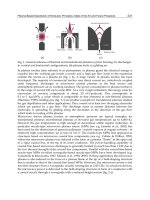
is presented as Fig 1(Huang Z. K. & Tien T. Y.,1996).
Fig. 1. Phase diagram of Y
2
O
3
- Si
3
N
4
subsystem
The reaction can be written as follows:
Si
3
N
4
+ Y
2
O
3
→Si
3
N
4
·Y
2
O
3
(Y
2
Si
3
N
4
O
3
, M)
Si
3
N
4
+SiO
2
+ 2 Y
2
O
3
→2(2 Y
2
O
3
·Si
2
N
2
O) ( Y
4
Si
2
N
2
O
7
, J )
The Gd
2
O
3
- Si
3
N
4
subsystem has similar phase relations and reactions.
SiC + Gd
2
O
3
+ SiO
2
+ 3/2N
2
→ Gd
2
O
3
·Si
3
N
4
(M phase) + CO
2
↑
Si
3
N
4
+SiO
2
+ 2 Gd
2
O
3
→2(2 Gd
2
O
3
·Si
2
N
2
O) ( Gd
4
Si
2
N
2
O
7
, J )
In the La
2
O
3
- Si
3
N
4
subsystem La
2
O
3
·2 Si
3
N
4
(monoclinic 2:1) was determined repeatedly
after hot-pressing under either Ar or N
2
atmosphere. A disputed La-melilite (La
2
O
3
: Si
3
N
4
)
was not found, because of the large radius of La
3+
ion. It could form only in bigger cell to be
La
2
O
3
. Si
2
N
2
O. AlN (La
2
Si
2
AlO
4
N
3
, melilite) by Al-N replaced for Si-N( Huang Z. K. & Chen
I. W.,1996). LaSiNO
2
(K phase, monoclinic) were determined because of the impurty of
powder. On the 2:1- La
2
O
3
join a richer-oxygen phase, 2 La
2
O
3
·Si
2
N
2
O (J-phase, monocl.)
was determined, indicating the presence of excess oxygen from SiO
2
impurity in the powder
mixtures. M.Mitomo (Mitomo M.,et.al. 1982)found that an equi-molar mixture of and heated
to 1800Ԩ showed that there were three temperature regions in which chemical reaction took
place.
High Temperature Phase Equilibrium of SiC-Based Ceramic Systems 447
for the phase relations and reactives in high temperature is beneficial to practical use in the
manufacture of SiC-based ceramics, as well as SiC/ Si
3
N
4
composites.
2. Experimental
The starting powders were α-SiC (H.C.Starck), β- Si
3
N
4
(H.C.Starck), La
2
O
3
, Gd
2
O
3
and Y
2
O
3
(R
2
O
3
with 99.9% purity, from Baotou Rare-earth Institute, China). The rare earth oxides were
calcined in air at 1200℃ for 2h before use.The compositions investigated were restricted to the
region bound by the poins SiC, Si
3
N
4
and R
2
O
3
(R=La,Gd,Y), but SiO
2
came from in situ
oxygen impurity on the surface of powders. Selected compositions were made by mixing the
required amounts of the starting powders in agate jar mills with absolute alcohol for 2hr. The
dried mixtures were hot-pressed in graphite dies 10 mm in diameter lined with BN in a
graphite resistance furnace under a pressure of 30MPa at a subsolidus temperature under a
mild flow of Ar, as well as N
2
used for comparison. For the systems SiC-R
2
O
3
, the melting
behaviours of SiC and R
2
O
3
(1:1 mole ratio) shown in the table 1. In which the subsolidus
temperatures were used as the hot-pressing temperatures for some compositions.
R
2
O
3
:SiC
(1:1)
Temperatures (
o
C)
R
2
O
3
1600 1700 1750 1800 1850 1900
La
2
O
3
not
melted
partly
melted
melted
Gd
2
O
3
not
melted
Little
melted
partly
melted
melted
Y
2
O
3
not
melted
Little
melted
Little
melted
partly
melted
melted
Table 1. Melting behaviors for R
2
O
3
: SiC (1:1)
The specimens were hot-pressed for 1 to 2 hr in the high temperature region and then
cooled at 200℃/min End points of hot-pressing were obtained where no further phase
change was observed when specimens were heated for longer times. An automatic
recording X-ray diffraction with monochromated CuKα radiation was used to scan the
samples at a rate of 2
o
/min.
3. Phase relation of binary subsystem
3.1 Phase relation of R
2
O
3
- Si
3
N
4
subsystem
Table 2 shows the phase relation for different Si
3
N
4
-R
2
O
3
binary subsystems in Ar or N
2
atmosphere respectively.
Si
3
N
4
- La
2
O
3
Si
3
N
4
-Gd
2
O
3
Si
3
N
4
-Y
2
O
3
Ar 2:1,K,J M,J M
N
2
2:1,K,J, M,J M,J
Table 2. phase relation of Si
3
N
4
-R
2
O
3
binary subsystem
In the Y
2
O
3
- Si
3
N
4
subsystem Y
2
O
3
- Si
3
N
4
mililite(M phase ) was determined after hot-
pressing under Ar and N
2
atmosphere. On the M- Y
2
O
3
join a richer-oxygen phase, 2
Y
2
O
3
·Si
2
N
2
O (J-phase, monocl.) was determined, The binary phase diagram of Y
2
O
3
- Si
3
N
4
under 1MPa N
2
is presented as Fig 1(Huang Z. K. & Tien T. Y.,1996).
Fig. 1. Phase diagram of Y
2
O
3
- Si
3
N
4
subsystem
The reaction can be written as follows:
Si
3
N
4
+ Y
2
O
3
→Si
3
N
4
·Y
2
O
3
(Y
2
Si
3
N
4
O
3
, M)
Si
3
N
4
+SiO
2
+ 2 Y
2
O
3
→2(2 Y
2
O
3
·Si
2
N
2
O) ( Y
4
Si
2
N
2
O
7
, J )
The Gd
2
O
3
- Si
3
N
4
subsystem has similar phase relations and reactions.
SiC + Gd
2
O
3
+ SiO
2
+ 3/2N
2
→ Gd
2
O
3
·Si
3
N
4
(M phase) + CO
2
↑
Si
3
N
4
+SiO
2
+ 2 Gd
2
O
3
→2(2 Gd
2
O
3
·Si
2
N
2
O) ( Gd
4
Si
2
N
2
O
7
, J )
In the La
2
O
3
- Si
3
N
4
subsystem La
2
O
3
·2 Si
3
N
4
(monoclinic 2:1) was determined repeatedly
after hot-pressing under either Ar or N
2
atmosphere. A disputed La-melilite (La
2
O
3
: Si
3
N
4
)
was not found, because of the large radius of La
3+
ion. It could form only in bigger cell to be
La
2
O
3
. Si
2
N
2
O. AlN (La
2
Si
2
AlO
4
N
3
, melilite) by Al-N replaced for Si-N( Huang Z. K. & Chen
I. W.,1996). LaSiNO
2
(K phase, monoclinic) were determined because of the impurty of
powder. On the 2:1- La
2
O
3
join a richer-oxygen phase, 2 La
2
O
3
·Si
2
N
2
O (J-phase, monocl.)
was determined, indicating the presence of excess oxygen from SiO
2
impurity in the powder
mixtures. M.Mitomo (Mitomo M.,et.al. 1982)found that an equi-molar mixture of and heated
to 1800Ԩ showed that there were three temperature regions in which chemical reaction took
place.
Properties and Applications of Silicon Carbide448
Si
3
N
4
+ La
2
O
3
Cto12501200
Si
3
N
4
+(La
4
Si
2
N
2
O
7
+LaSiNO
2
)
Cto15001400
LaSiNO
2
+ Si
3
N
4
Cto17501650
La
2
O
3
·2 Si
3
N
4
+liquid
3.2 Phase relation of R
2
O
3
-SiC subsystem
No new phase was detected in SiC- Si
3
N
4
and SiC-R
2
O
3
(R=La,Gd,Y) systems, it can be due
to its very low self-diffusion coefficient of Si and C with very strong covalence of Si-C bond.
However, a few of 2R
2
O
3
·Si
2
N
2
O (J phase)was observed in SiC-R
2
O
3
system. The oxygen
content of SiC powder, existing either as surface SiO
2
or as interstitial oxygen is between 0.8
to 1.1wt%. The reduction of SiC (lower X-ray peak intensity of SiC) indicated that a part of
SiC could directly react with R
2
O
3
after being oxidized/nitrided under N
2
. The reaction can
be written as follows:
3SiC + 2N
2
Si
3
N
4
+ 3C,
4R
2
O
3
+ SiO
2
+ Si
3
N
4
2(2R
2
O
3
. Si
2
N
2
O) (J phase)
It should be noted that only a little amount of oxygen content is enough to form much more
rare-earth silicon-oxynitrides as shown below: For the examples of La-siliconoxynitrides,
one mole of oxygen can cause formation of 2 moles of J phase (La), (Si
2
N
2
O.2La
2
O
3
). It
means that 1 wt% O
2
can cause formation of 47.0 wt% J(La) phase.
In fact, it is difficult to make SiC reaction under N
2
, but when rare-earth oxide entered in
system, SiC can be reacted even at lower temperature ( 1550Ԩ for SiC- La
2
O
3
, 1600Ԩ for
SiC-Gd
2
O
3
system ). The addition of rare-earth oxide benefits the nitride reaction of SiC.
Table 3 shows the phase relation in SiC -R
2
O
3
binary system in different atmosphere.
SiC- La
2
O
3
SiC-Gd
2
O
3
SiC-Y
2
O
3
Ar No reaction No reaction No reaction
N
2
J, SiC J, SiC J,SiC
Table 3. Formed phase of SiC:R
2
O
3
=1:1 compositions
4. The phase equilibrium of SiC-Si
3
N
4
-R
2
O
3
The binary phases of La
2
O
3
·2Si
3
N
4
and Si
3
N
4
.R
2
O
3
(M(Gd),M(Y)) coexist with SiC forming a
tie-line which separated every ternary system of SiC- Si
3
N
4
-R
2
O
3
(R=La,Gd,Y) into two
triangles, respectively. The 2R
2
O
3
·Si
2
N
2
O (J phase) also coexist with SiC forming another tie-
line in triangle near R
2
O
3
side. Based on the experimental results of binary subsystem, the
subsolidus phase diagrams of SiC- Si
3
N
4
-R
2
O
3
(R=La,Gd,Y) systems are presented as Fig.
2.Comparing SiC- Si
3
N
4
-R
2
O
3
with AlN- Si
3
N
4
-R
2
O
3
systems (Cao G.Z., et.al,1989) reported
by Cao G.Z. et, the similarity is evident except SiC couldn’t participate to form -Sialon
because of its tough Si-C bond with bigger bond length 1.89Å.
The XRD pattern of typical sample after hot-pressed of SiC- Si
3
N
4
-Y
2
O
3
system in N
2
atmosphere is shown in Fig3, phase analysis indicated that M phase (Si
3
N
4
·Y
2
O
3
), K phase
(Si
2
N
2
O·Y
2
O
3
), or J phase (Si
2
N
2
O·2Y
2
O
3
) were formed. And in these samples, SiC coexisted
with M, K-phase (Fig3-a) , coexisted with Si
3
N
4
, M-phase(Fig3-b) and with Y
2
O
3
,J
phase(Fig3-c). But in sample sintered in Ar atmosphere, K phase had formed instead of J
phase(Fig4). The reason is higher oxygen partial pressure in Ar atmosphere. The
introduction of Si
2
N
2
O transformed the ternary system into the quaternary system. In the
system, three compatible tetrahedrons, namely, SiC-M-K-J,SiC-M-J-Y
2
O
3
, SiC- Si
3
N
4
-M-K
(in N
2
) or SiC- Si
3
N
4
-M-J(in Ar) have been determined. SiC and Si
3
N
4
would selectively
equilibrate with these three phases in the order of M < K < J < Y
2
O
3
with respect to the
effects of the oxygen content of SiC and Si
3
N
4
powders and the oxygen partial pressure in high
temperature. Based on those results, the subsolid phase diagram for the ternary SiC-Si
3
N
4
-Y
2
O
3
system and the quaternary SiC- Si
3
N
4
-Si
2
N
2
O-Y
2
O
3
system are given in Fig 5.
Fig. 2. Subsolidus phase diagram of the system SiC-Si
3
N
4
-R
2
O
3
in Ar or N
2
10 20 30 40 50 60 70
( a )
( b )
( c )
Y
2
O
3
J
Si
3
N
4
K
S iC
M
I / a. u.
2 θ / °
Fig. 3. XRD pattern of SiC-Si
3
N
4
-Y
2
O
3
hot pressed sample in N
2
Si
3
N
4
SiC
M
Mol %
M: R
2
O
3
.
Si
3
N
4
(R
2
Si
3
O
3
N
4
)
J: 2R
2
O
3
.
Si
2
N
2
O
(R
4
Si
2
O
7
N
2
)
J
R
2
O
3
(R=Gd,Y)
La
2
O
3
Si
3
N
4
SiC
2:1
Mol%
2:1: La
2
O
3
.
2Si
3
N
4
(La
2
Si
6
O
3
N
8
)
J: 2La
2
O
3
.
Si
2
N
2
O
(La
4
Si
2
O
7
N
2
)
J
High Temperature Phase Equilibrium of SiC-Based Ceramic Systems 449
Si
3
N
4
+ La
2
O
3
Cto12501200
Si
3
N
4
+(La
4
Si
2
N
2
O
7
+LaSiNO
2
)
Cto15001400
LaSiNO
2
+ Si
3
N
4
Cto17501650
La
2
O
3
·2 Si
3
N
4
+liquid
3.2 Phase relation of R
2
O
3
-SiC subsystem
No new phase was detected in SiC- Si
3
N
4
and SiC-R
2
O
3
(R=La,Gd,Y) systems, it can be due
to its very low self-diffusion coefficient of Si and C with very strong covalence of Si-C bond.
However, a few of 2R
2
O
3
·Si
2
N
2
O (J phase)was observed in SiC-R
2
O
3
system. The oxygen
content of SiC powder, existing either as surface SiO
2
or as interstitial oxygen is between 0.8
to 1.1wt%. The reduction of SiC (lower X-ray peak intensity of SiC) indicated that a part of
SiC could directly react with R
2
O
3
after being oxidized/nitrided under N
2
. The reaction can
be written as follows:
3SiC + 2N
2
Si
3
N
4
+ 3C,
4R
2
O
3
+ SiO
2
+ Si
3
N
4
2(2R
2
O
3
. Si
2
N
2
O) (J phase)
It should be noted that only a little amount of oxygen content is enough to form much more
rare-earth silicon-oxynitrides as shown below: For the examples of La-siliconoxynitrides,
one mole of oxygen can cause formation of 2 moles of J phase (La), (Si
2
N
2
O.2La
2
O
3
). It
means that 1 wt% O
2
can cause formation of 47.0 wt% J(La) phase.
In fact, it is difficult to make SiC reaction under N
2
, but when rare-earth oxide entered in
system, SiC can be reacted even at lower temperature ( 1550Ԩ for SiC- La
2
O
3
, 1600Ԩ for
SiC-Gd
2
O
3
system ). The addition of rare-earth oxide benefits the nitride reaction of SiC.
Table 3 shows the phase relation in SiC -R
2
O
3
binary system in different atmosphere.
SiC- La
2
O
3
SiC-Gd
2
O
3
SiC-Y
2
O
3
Ar No reaction No reaction No reaction
N
2
J, SiC J, SiC J,SiC
Table 3.
Formed phase of SiC:R
2
O
3
=1:1 compositions
4. The phase equilibrium of SiC-Si
3
N
4
-R
2
O
3
The binary phases of La
2
O
3
·2Si
3
N
4
and Si
3
N
4
.R
2
O
3
(M(Gd),M(Y)) coexist with SiC forming a
tie-line which separated every ternary system of SiC- Si
3
N
4
-R
2
O
3
(R=La,Gd,Y) into two
triangles, respectively. The 2R
2
O
3
·Si
2
N
2
O (J phase) also coexist with SiC forming another tie-
line in triangle near R
2
O
3
side. Based on the experimental results of binary subsystem, the
subsolidus phase diagrams of SiC- Si
3
N
4
-R
2
O
3
(R=La,Gd,Y) systems are presented as Fig.
2.Comparing SiC- Si
3
N
4
-R
2
O
3
with AlN- Si
3
N
4
-R
2
O
3
systems (Cao G.Z., et.al,1989) reported
by Cao G.Z. et, the similarity is evident except SiC couldn’t participate to form -Sialon
because of its tough Si-C bond with bigger bond length 1.89Å.
The XRD pattern of typical sample after hot-pressed of SiC- Si
3
N
4
-Y
2
O
3
system in N
2
atmosphere is shown in Fig3, phase analysis indicated that M phase (Si
3
N
4
·Y
2
O
3
), K phase
(Si
2
N
2
O·Y
2
O
3
), or J phase (Si
2
N
2
O·2Y
2
O
3
) were formed. And in these samples, SiC coexisted
with M, K-phase (Fig3-a) , coexisted with Si
3
N
4
, M-phase(Fig3-b) and with Y
2
O
3
,J
phase(Fig3-c). But in sample sintered in Ar atmosphere, K phase had formed instead of J
phase(Fig4). The reason is higher oxygen partial pressure in Ar atmosphere. The
introduction of Si
2
N
2
O transformed the ternary system into the quaternary system. In the
system, three compatible tetrahedrons, namely, SiC-M-K-J,SiC-M-J-Y
2
O
3
, SiC- Si
3
N
4
-M-K
(in N
2
) or SiC- Si
3
N
4
-M-J(in Ar) have been determined. SiC and Si
3
N
4
would selectively
equilibrate with these three phases in the order of M < K < J < Y
2
O
3
with respect to the
effects of the oxygen content of SiC and Si
3
N
4
powders and the oxygen partial pressure in high
temperature. Based on those results, the subsolid phase diagram for the ternary SiC-Si
3
N
4
-Y
2
O
3
system and the quaternary SiC- Si
3
N
4
-Si
2
N
2
O-Y
2
O
3
system are given in Fig 5.
Fig. 2. Subsolidus phase diagram of the system SiC-Si
3
N
4
-R
2
O
3
in Ar or N
2
10 20 30 40 50 6 0 70
( a )
( b )
( c )
Y
2
O
3
J
Si
3
N
4
K
S iC
M
I / a. u.
2 θ / °
Fig. 3. XRD pattern of SiC-Si
3
N
4
-Y
2
O
3
hot pressed sample in N
2
Si
3
N
4
SiC
M
Mol %
M: R
2
O
3
.
Si
3
N
4
(R
2
Si
3
O
3
N
4
)
J: 2R
2
O
3
.
Si
2
N
2
O
(R
4
Si
2
O
7
N
2
)
J
R
2
O
3
(R=Gd,Y)
La
2
O
3
Si
3
N
4
SiC
2:1
Mol%
2:1: La
2
O
3
.
2Si
3
N
4
(La
2
Si
6
O
3
N
8
)
J: 2La
2
O
3
.
Si
2
N
2
O
(La
4
Si
2
O
7
N
2
)
J
Properties and Applications of Silicon Carbide450
1 0 2 0 3 0 4 0 5 0 6 0 7 0
( c )
( b )
( a )
S iC
J
S i
3
N
4
M
I / a. u .
2 θ / °
Fig. 4. XRD pattern of SiC-Si
3
N
4
-Y
2
O
3
hot pressed sample in Ar
Fig. 5. Subsolidus phase diagram of SiC- Si
3
N
4
-Si
2
N
2
O-Y
2
O
3
system( a: in N
2
,b:in Ar
1 0 2 0 3 0 4 0 5 0 6 0
0
1 0 0
2 0 0
3 0 0
4 0 0
5 0 0
6 0 0
7 0 0
8 0 0
2 : 1
2 : 1
2 : 1
2 : 1
2 : 1
2 : 1
2 : 1
2 : 1
2 : 1
2 : 1
2 : 1
2 : 1
H
2 : 1
2 : 1
2 : 1
2 : 1
2 : 1
2 : 1
H
S N
S N
S N
S N
S N
S N
S N
S C
S C
S C
S C
H
H
H
H
H
H
H
H
2 : 1
I / a . u .
2 θ / °
Fig. 6. XRD pattern of SiC-Si
3
N
4
-
2
:1-H showing coexistence of four phases in the system SiC-
Si
3
N
4
-La
2
O
3
-SiO
2
.
Si
3
N
4
Y
2
O
3
SiC
J
M
K
Si
2
N
2
O
mol%
Si
3
N
4
Y
2
O
3
SiC
J
M
K
Si
2
N
2
O
mol%
Fig. 7. Subsolidus phase diagram of the system Si
3
N
4
-SiO
2
-La
2
O
3
in Ar or N
2
[9,13]
As the typical example, Fig 6 showed XRD patterns of four phase coexistence in two typical
tetrahedrons respectively in SiC- Si
3
N
4
-La
2
O
3
system. The oxygen-richer rare-earth silicon-
oxynitrides phase La
5
(SiO
4
)
3
N (H phase) had been indicated in this system. K-phase
(Si
2
N
2
O·La
2
O
3
) 2La
2
O
3
·Si
2
N
2
O (J-phase) were indicated in this system similar with Si
3
N
4
-
La
2
O
3
system, in which J phase also occurred on the binary composition Si
3
N
4
:2La
2
O
3
. It
indicates that the formation of above oxynitrides was related to the presence of excess
oxygen from SiO
2
impurity in the powder mixtures. It should be noted that these oxygen-
richer rare-earth silicon-oxynitrides do not lie on the plane SiC- Si
3
N
4
-La
2
O
3
even so
synthesized by these three powders, but lie in the Si
3
N
4
-SiO
2
-La
2
O
3
system . The isothermal
section at 1700
o
C of Si
3
N
4
-SiO
2
-La
2
O
3
system was reported by M.Mitomo(M.Mitomo,1982).
Where he obtained J- and K-phase by crystallization from liquid phase, because they lie by a
liquid area. In the present work they were obtained directly by solid-state reaction under
hot-pressing at 1550℃ and led to construct the subsolidus phase relations of Si
3
N
4
-SiO
2
-
La
2
O
3
system (Fig. 7)( Toropov,et al ,1962, Mitomo,1982) showing some similarity in both.
Above all the oxygen-richer rare-earth silicon-oxynitrides and the three members of ternary
systems Si
3
N
4
-SiO
2
-La
2
O
3
were compatible with SiC forming ten four-phase compatibility
tetrahedrons as follows:
SiC-Si
3
N
4
-2:1-H, SiC-Si
3
N
4
-H-Si
2
N
2
O, SiC-H-Si
2
N
2
O-1:
2
, SiC-Si
2
N
2
O-1:2-SiO
2
, SiC-2:1-K-H,
SiC-2:1-K-J, SiC-K-J-H, SiC-2:1-J-La
2
O
3
, SiC-J-La
2
O
3
-H, SiC-H-La
2
O
3
-1:1.
The subsolidus phase relationship of this quaternary system with ten four-phase
compatibility tetrahedrons is plotted in Fig 8.
2:1: La
2
O
3
.
2Si
3
N
4
(La
2
Si
3
O
3
N
4
)
K: La
2
O
3
.
Si
2
N
2
O
(LaSiNO
2
)
J: 2La
2
O
3
.
Si
2
N
2
O
(La
2
SiNO
3.5
)
H: La
4.67
(SiO
4
)
3
O
La
5
(SiO
4
)
3
N
1:1: La
2
SiO
5
1:2: La
2
Si
2
O
7
La
2
O
3
Si
3
N
4
SiO
2
Si
2
N
2
O
J
K
2:1
Mol %
1:1
1:2
H
High Temperature Phase Equilibrium of SiC-Based Ceramic Systems 451
1 0 2 0 3 0 4 0 5 0 6 0 7 0
( c )
( b )
( a )
S iC
J
S i
3
N
4
M
I / a. u .
2 θ / °
Fig. 4. XRD pattern of SiC-Si
3
N
4
-Y
2
O
3
hot pressed sample in Ar
Fig. 5. Subsolidus phase diagram of SiC- Si
3
N
4
-Si
2
N
2
O-Y
2
O
3
system( a: in N
2
,b:in Ar
1 0 2 0 3 0 4 0 5 0 6 0
0
1 0 0
2 0 0
3 0 0
4 0 0
5 0 0
6 0 0
7 0 0
8 0 0
2 : 1
2 : 1
2 : 1
2 : 1
2 : 1
2 : 1
2 : 1
2 : 1
2 : 1
2 : 1
2 : 1
2 : 1
H
2 : 1
2 : 1
2 : 1
2 : 1
2 : 1
2 : 1
H
S N
S N
S N
S N
S N
S N
S N
S C
S C
S C
S C
H
H
H
H
H
H
H
H
2 : 1
I / a . u .
2 θ / °
Fig. 6. XRD pattern of SiC-Si
3
N
4
-
2
:1-H showing coexistence of four phases in the system SiC-
Si
3
N
4
-La
2
O
3
-SiO
2
.
Si
3
N
4
Y
2
O
3
SiC
J
M
K
Si
2
N
2
O
mol%
Si
3
N
4
Y
2
O
3
SiC
J
M
K
Si
2
N
2
O
mol%
Fig. 7. Subsolidus phase diagram of the system Si
3
N
4
-SiO
2
-La
2
O
3
in Ar or N
2
[9,13]
As the typical example, Fig 6 showed XRD patterns of four phase coexistence in two typical
tetrahedrons respectively in SiC- Si
3
N
4
-La
2
O
3
system. The oxygen-richer rare-earth silicon-
oxynitrides phase La
5
(SiO
4
)
3
N (H phase) had been indicated in this system. K-phase
(Si
2
N
2
O·La
2
O
3
) 2La
2
O
3
·Si
2
N
2
O (J-phase) were indicated in this system similar with Si
3
N
4
-
La
2
O
3
system, in which J phase also occurred on the binary composition Si
3
N
4
:2La
2
O
3
. It
indicates that the formation of above oxynitrides was related to the presence of excess
oxygen from SiO
2
impurity in the powder mixtures. It should be noted that these oxygen-
richer rare-earth silicon-oxynitrides do not lie on the plane SiC- Si
3
N
4
-La
2
O
3
even so
synthesized by these three powders, but lie in the Si
3
N
4
-SiO
2
-La
2
O
3
system . The isothermal
section at 1700
o
C of Si
3
N
4
-SiO
2
-La
2
O
3
system was reported by M.Mitomo(M.Mitomo,1982).
Where he obtained J- and K-phase by crystallization from liquid phase, because they lie by a
liquid area. In the present work they were obtained directly by solid-state reaction under
hot-pressing at 1550℃ and led to construct the subsolidus phase relations of Si
3
N
4
-SiO
2
-
La
2
O
3
system (Fig. 7)( Toropov,et al ,1962, Mitomo,1982) showing some similarity in both.
Above all the oxygen-richer rare-earth silicon-oxynitrides and the three members of ternary
systems Si
3
N
4
-SiO
2
-La
2
O
3
were compatible with SiC forming ten four-phase compatibility
tetrahedrons as follows:
SiC-Si
3
N
4
-2:1-H, SiC-Si
3
N
4
-H-Si
2
N
2
O, SiC-H-Si
2
N
2
O-1:
2
, SiC-Si
2
N
2
O-1:2-SiO
2
, SiC-2:1-K-H,
SiC-2:1-K-J, SiC-K-J-H, SiC-2:1-J-La
2
O
3
, SiC-J-La
2
O
3
-H, SiC-H-La
2
O
3
-1:1.
The subsolidus phase relationship of this quaternary system with ten four-phase
compatibility tetrahedrons is plotted in Fig 8.
2:1: La
2
O
3
.
2Si
3
N
4
(La
2
Si
3
O
3
N
4
)
K: La
2
O
3
.
Si
2
N
2
O
(LaSiNO
2
)
J: 2La
2
O
3
.
Si
2
N
2
O
(La
2
SiNO
3.5
)
H: La
4.67
(SiO
4
)
3
O
La
5
(SiO
4
)
3
N
1:1: La
2
SiO
5
1:2: La
2
Si
2
O
7
La
2
O
3
Si
3
N
4
SiO
2
Si
2
N
2
O
J
K
2:1
Mol %
1:1
1:2
H
Properties and Applications of Silicon Carbide452
Fig. 8. Subsolidus phase diagram of the system SiC-Si
3
N
4
-La
2
O
3
-SiO
2
in N
2
or Ar
Fig. 8. Subsolidus phase diagram of the system SiC-Si
3
N
4
-La
2
O
3
-SiO
2
in N
2
or Ar
In the Si
3
N
4
-SiC-Gd
2
O
3
system, the M-phase(Si
3
N
4
·Gd
2
O
3
、J-phase(Si
2
N
2
O·2Gd
2
O
3
) and H-
phase(Gd
10
(SiO
4
)
6
N
2
)were indicated, a typical XRD pattern of hot-pressure in 1700℃ is
shown in Fig 9.
10 2 0 30 4 0 50 60
0
50
10 0
15 0
20 0
25 0
30 0
35 0
40 0
45 0
50 0
M
H
H
H
H
H
H
H
M
M
M
M
M
M
M
M
M
M
SC
SC
SC
SN
SN
SN
SN
SN
SN
I / a . u .
2 θ / °
M
SN
SC
Fig. 9. XRD pattern of SiC-Si
3
N
4
-M(Gd)-H(Gd) four-phases coexistence in the system SiC-
Si
3
N
4
-Gd
2
O
3
-SiO
2
.
La
2
O
3
Si
3
N
4
SiO
2
Si
2
N
2
O
J
K
2:1
Mol %
1:1
1:2
H
SiC
Table 4 shows the phase analysis of different compositions in Si
3
N
4
-SiC-Gd
2
O
3
system. With
the increasing of SiC and Si
3
N
4
, which means the increasing oxygen content in system, M-
phase, J-phase and H-phase would be formed. In the Ar atmosphere, H-phase, which is
more oxygen-rich inclined to generation than in N
2
since the higher oxygen particle
pressure.
vs: very strong, s: strong, m: middle w: weak
Table 4. The compositions of raw material and phase compositions in ternary systems SiC-
Si
3
N
4
-Gd
2
O
3
(in Ar or N
2
,1700Ԩ)
Fig. 10. Subsolidus phase diagram of the system SiC-Si
3
N
4
-Gd
2
O
3
-SiO
2
in Ar or N
2
No. the composition of raw
material /mol
Phase composition(in Ar) Phase composition (in
N
2
)
1#
SiC: Si
3
N
4
:Gd
2
O
3
= 4:
4:1
M(vs),Si
3
N
4
(s),SiC(m),H(w)
M(vs), Si
3
N
4
(s),
H(m),SiC(w)
2#
SiC: Si
3
N
4
:Gd
2
O
3
= 1:
1:1
M(vs),J(m),SiC(w) M(vs),J(m),SiC(w)
3#
SiC: Si
3
N
4
:Gd
2
O
3
= 1:
1:2
J(s),H(m),SiC(w) J(s),SiC(w)
4#
SiC: Si
3
N
4
:Gd
2
O
3
= 1:
1:4
J(s),Gd
2
O
3
(w) J(vs),SiC(m),Gd
2
O
3
(w)
SiC
Gd
2
O
3
Si
3
N
4
SiO
2
Si
2
N
2
O
J
M
Mol %
H
1:2
M: Gd
2
O
3
.
Si
3
N
4
J: 2Gd
2
O
3
.
Si
2
N
2
O
H: Gd
4.67
(SiO
4
)
3
O
1:1: Gd
2
O
3
.
SiO
2
1:2: Gd
2
O
3
.
2SiO
2
1:1
H
High Temperature Phase Equilibrium of SiC-Based Ceramic Systems 453
Fig. 8. Subsolidus phase diagram of the system SiC-Si
3
N
4
-La
2
O
3
-SiO
2
in N
2
or Ar
Fig. 8. Subsolidus phase diagram of the system SiC-Si
3
N
4
-La
2
O
3
-SiO
2
in N
2
or Ar
In the Si
3
N
4
-SiC-Gd
2
O
3
system, the M-phase(Si
3
N
4
·Gd
2
O
3
、J-phase(Si
2
N
2
O·2Gd
2
O
3
) and H-
phase(Gd
10
(SiO
4
)
6
N
2
)were indicated, a typical XRD pattern of hot-pressure in 1700℃ is
shown in Fig 9.
10 2 0 30 4 0 50 60
0
50
10 0
15 0
20 0
25 0
30 0
35 0
40 0
45 0
50 0
M
H
H
H
H
H
H
H
M
M
M
M
M
M
M
M
M
M
SC
SC
SC
SN
SN
SN
SN
SN
SN
I / a . u .
2 θ / °
M
SN
SC
Fig. 9. XRD pattern of SiC-Si
3
N
4
-M(Gd)-H(Gd) four-phases coexistence in the system SiC-
Si
3
N
4
-Gd
2
O
3
-SiO
2
.
La
2
O
3
Si
3
N
4
SiO
2
Si
2
N
2
O
J
K
2:1
Mol %
1:1
1:2
H
SiC
Table 4 shows the phase analysis of different compositions in Si
3
N
4
-SiC-Gd
2
O
3
system. With
the increasing of SiC and Si
3
N
4
, which means the increasing oxygen content in system, M-
phase, J-phase and H-phase would be formed. In the Ar atmosphere, H-phase, which is
more oxygen-rich inclined to generation than in N
2
since the higher oxygen particle
pressure.
vs: very strong, s: strong, m: middle w: weak
Table 4. The compositions of raw material and phase compositions in ternary systems SiC-
Si
3
N
4
-Gd
2
O
3
(in Ar or N
2
,1700Ԩ)
Fig. 10. Subsolidus phase diagram of the system SiC-Si
3
N
4
-Gd
2
O
3
-SiO
2
in Ar or N
2
No. the composition of raw
material /mol
Phase composition(in Ar) Phase composition (in
N
2
)
1#
SiC: Si
3
N
4
:Gd
2
O
3
= 4:
4:1
M(vs),Si
3
N
4
(s),SiC(m),H(w)
M(vs), Si
3
N
4
(s),
H(m),SiC(w)
2#
SiC: Si
3
N
4
:Gd
2
O
3
= 1:
1:1
M(vs),J(m),SiC(w) M(vs),J(m),SiC(w)
3#
SiC: Si
3
N
4
:Gd
2
O
3
= 1:
1:2
J(s),H(m),SiC(w) J(s),SiC(w)
4#
SiC: Si
3
N
4
:Gd
2
O
3
= 1:
1:4
J(s),Gd
2
O
3
(w) J(vs),SiC(m),Gd
2
O
3
(w)
SiC
Gd
2
O
3
Si
3
N
4
SiO
2
Si
2
N
2
O
J
M
Mol %
H
1:2
M: Gd
2
O
3
.
Si
3
N
4
J: 2Gd
2
O
3
.
Si
2
N
2
O
H: Gd
4.67
(SiO
4
)
3
O
1:1: Gd
2
O
3
.
SiO
2
1:2: Gd
2
O
3
.
2SiO
2
1:1
H
Properties and Applications of Silicon Carbide454
The compositions in the triangles bounded by R-SiC tielines and Gd
2
O
3
always led to the
formation of rare-earth silicon-oxynitrides, indicating the presences of excess oxygen in the
powder mixture, that means SiO
2
in powder also participated in the reaction in the system.
Presence of SiO
2
leads to the quasiternary system Si
3
N
4
-SiC-Gd
2
O
3
extend into the
quaternary system Si
3
N
4
-SiC-SiO
2
-Gd
2
O
3
. All rare earth silicon-oxinitrides wrer compatible
with SiC, forming eight four-phases compatibility terahedrons as follows:
SiC-Si
3
N
4
-M-H, SiC-Si
3
N
4
-H-Si
2
N
2
O, SiC-H-Si
2
N
2
O-1:2, SiC-Si
2
N
2
O-1:2-SiO
2
, SiC-M-J-H, SiC-
M-J-Gd
2
O
3
, SiC-J-Gd
2
O
3
-H, SiC-H-Gd
2
O
3
-1:1,
Hence the subsolidus phase diagram of this quaternary system is plotted in Fig. 10.
5. The high temperature reaction
Generally, the oxygen content of SiC powder, existing either as surface SiO
2
or as interstitial
oxygen is between 0.8 to 1.1wt%. More than 1.5% of oxygen content exists in Si
3
N
4
powder.
The in-situ SiO
2
coexisting with powder mixture leads to the quasiternary systems SiC-
Si
3
N
4
-R
2
O
3
extend into the quaternary systems SiC-Si
3
N
4
-SiO
2
-R
2
O
3
(R=La,Gd,Y).Just as
discussed, only a little amount of oxygen content is enough to form much more rare-earth
siliconoxynitrides. That is the reason for easier and much more formation of oxygen-richer
rare-earth siliconoxynitrides in the present systems. Their formations are essentially based
on the reactions of SiO
2
and Si
3
N
4
with R
2
O
3
, but without Si
2
N
2
O presence as following:
J(R): 4R
2
O
3
+ SiO
2
+ Si
3
N
4
2(Si
2
N
2
O.
2
R
2
O
3
),
K(R): 2R
2
O
3
+ SiO
2
+ Si
3
N
4
2(Si
2
N
2
O.R
2
O
3
),
H(R): 10R
2
O
3
+ 9SiO
2
+ Si
3
N
4
4(R
5
(SiO
4
)
3
N),
The formation of oxygen-richer rare-earth siliconoxynitrides are often accompanied with not
only consuming Si
3
N
4
but also reducing SiC (much lower X-ray peak intensity of SiC)
specific when hot-pressing under N
2
atmosphere. This implies that a part of SiC could also
directly react with R
2
O
3
after being oxidised/nitrided. A few of
2
R
2
O
3
·Si
2
N
2
O were observed
from SiC-R
2
O
3
binary system when firing in N
2
atmosphere. In this case the reactions of SiC
and R
2
O
3
can be written as follows:
SiC + O
2
→SiO
2
+ C,
4SiO
2
+ 2N
2
→2Si
2
N
2
O + 3O
2
;
4SiC + O
2
+ 2N
2
→ 2Si
2
N
2
O + 4C;
3SiC + 2N
2
→ Si
3
N
4
+ 3C,
then 2SiC + 2R
2
O
3
+ N
2
+ 1.5O
2
2R
2
O
3
·Si
2
N
2
O (J phase) + 2CO.
2SiC + R
2
O
3
+ N
2
+ 1.5O
2
R
2
O
3
·Si
2
N
2
O (K phase) +
2
CO.
6SiC + 5R
2
O
3
+ N
2
+ 7.5O
2
2(R
5
(SiO
4
)
3
N) (H phase) + 6CO.
3SiC + R
2
O
3
+ 2N
2
R
2
O
3
. Si
3
N
4
(M phase) + 3C.
Table 5 summarizes the formation of rare-earth silicon-oxynitrides in the present systems,
indicating the trend of formation lessens with decreasing bond ionicity from SiO
2
to SiC.
Ionicity La
2
O
3
Gd
2
O
3
Y
2
O
3
SiO
2
5 2:1,H*,1:1 2:1,H*,1:1 2:1,H*,1:1
Si
2
N
2
O 4# J(1:2),K(1:1),H** J(1:2),H** J(1:2) ,K(1:1),H**
Si
3
N
4
3 2:1 M(1:1) M(1:1)
SiC (in Ar) 2 No No No
SiC (in N
2
)## 2 J J J
*H : R
4
.
67
(SiO
4
)
3
O.
**H: R
5
(SiO
4
)
3
N or 5R
2
O
3
.
4
SiO
2
.Si
2
N
2
O.
# Ionicity of Si
2
N
2
O : 5 for Si-O bond,
3
for Si-N bond.
##A few of J phase formed.
Table 5. Formation of some rare-earth siliconoxynitrides (mole ratio)
6. Conclusion
Subsolidus phase diagrams of the ternary systems SiC- Si
3
N
4
-R
2
O
3
(R=La,Gd,Y) were
determined. The in-situ SiO
2
impurity in the powder mixtures leads to form some oxygen-
richer rare-earth siliconoxynitrides and extend the quasiternary systems into quaternary
system of SiC-Si
3
N
4
-SiO
2
-R
2
O
3
. The phase relations of these quaternary systems were
established with several SiC-containing four-phase compatibility tetrahedrons. The
formation of oxygen-richer rare-earth siliconoxynitrides was discussed. When firing under
nitrogen atmosphere a part of SiC could also directly tend to react with R
2
O
3
after being
oxidised/nitrided forming some rare-earth siliconoxynitrides. They all contributed to
construct the phase diagrams of quaternary systems SiC- Si
3
N
4
-SiO
2
-R
2
O
3
.
Acknowledgements
This study was supported by National Natural Science Foundation of China (50962001). The
authors are grateful to Mr. Jiang and Mr. Han for their assistance.
7. References
Nitin P. Padture. (1994)In situ-toughened silicon carbide. J.Am.Ceram.Soc., 1994,77[2]519-
523 ISSN :1551-2916
Kim Y. & Mitomo.M . (2000) Fabrication and mechanical properties of silicon carbide-silicon
nitride nanocomposites. J. materail Science. 35(2000)5885-5890 ISSN :0022-2461
Lee Y,Kim Y., Choi H., .Lee J.(2001) Effects of additive amount on microstructure and
mechanical properties of silicon carbide –silicon nitride composite J. material
Science. 36(2001)699-702 ISSN :0022-2461
Becher P.F., Sun Y., Hsueh C., Alexander,K., et (1996) Debonding of interfaces between beta
silicon nitride and Si-Al-Y oxynitride glass Acta Mater., 1996, 44 3881-3893
ISSN :1359-6454
Keeebe H., Pezzotti G., Ziegler G.(1999) Microstructure and fracture toughness of Si
3
N
4
ceramics : combined roles of grain morphology and secondary phase chemistry
J.Am. Ceram. Soc., 1999, 82,1642-1644 ISSN :1551-2916
High Temperature Phase Equilibrium of SiC-Based Ceramic Systems 455
The compositions in the triangles bounded by R-SiC tielines and Gd
2
O
3
always led to the
formation of rare-earth silicon-oxynitrides, indicating the presences of excess oxygen in the
powder mixture, that means SiO
2
in powder also participated in the reaction in the system.
Presence of SiO
2
leads to the quasiternary system Si
3
N
4
-SiC-Gd
2
O
3
extend into the
quaternary system Si
3
N
4
-SiC-SiO
2
-Gd
2
O
3
. All rare earth silicon-oxinitrides wrer compatible
with SiC, forming eight four-phases compatibility terahedrons as follows:
SiC-Si
3
N
4
-M-H, SiC-Si
3
N
4
-H-Si
2
N
2
O, SiC-H-Si
2
N
2
O-1:2, SiC-Si
2
N
2
O-1:2-SiO
2
, SiC-M-J-H, SiC-
M-J-Gd
2
O
3
, SiC-J-Gd
2
O
3
-H, SiC-H-Gd
2
O
3
-1:1,
Hence the subsolidus phase diagram of this quaternary system is plotted in Fig. 10.
5. The high temperature reaction
Generally, the oxygen content of SiC powder, existing either as surface SiO
2
or as interstitial
oxygen is between 0.8 to 1.1wt%. More than 1.5% of oxygen content exists in Si
3
N
4
powder.
The in-situ SiO
2
coexisting with powder mixture leads to the quasiternary systems SiC-
Si
3
N
4
-R
2
O
3
extend into the quaternary systems SiC-Si
3
N
4
-SiO
2
-R
2
O
3
(R=La,Gd,Y).Just as
discussed, only a little amount of oxygen content is enough to form much more rare-earth
siliconoxynitrides. That is the reason for easier and much more formation of oxygen-richer
rare-earth siliconoxynitrides in the present systems. Their formations are essentially based
on the reactions of SiO
2
and Si
3
N
4
with R
2
O
3
, but without Si
2
N
2
O presence as following:
J(R): 4R
2
O
3
+ SiO
2
+ Si
3
N
4
2(Si
2
N
2
O.
2
R
2
O
3
),
K(R): 2R
2
O
3
+ SiO
2
+ Si
3
N
4
2(Si
2
N
2
O.R
2
O
3
),
H(R): 10R
2
O
3
+ 9SiO
2
+ Si
3
N
4
4(R
5
(SiO
4
)
3
N),
The formation of oxygen-richer rare-earth siliconoxynitrides are often accompanied with not
only consuming Si
3
N
4
but also reducing SiC (much lower X-ray peak intensity of SiC)
specific when hot-pressing under N
2
atmosphere. This implies that a part of SiC could also
directly react with R
2
O
3
after being oxidised/nitrided. A few of
2
R
2
O
3
·Si
2
N
2
O were observed
from SiC-R
2
O
3
binary system when firing in N
2
atmosphere. In this case the reactions of SiC
and R
2
O
3
can be written as follows:
SiC + O
2
→SiO
2
+ C,
4SiO
2
+ 2N
2
→2Si
2
N
2
O + 3O
2
;
4SiC + O
2
+ 2N
2
→ 2Si
2
N
2
O + 4C;
3SiC + 2N
2
→ Si
3
N
4
+ 3C,
then 2SiC + 2R
2
O
3
+ N
2
+ 1.5O
2
2R
2
O
3
·Si
2
N
2
O (J phase) + 2CO.
2SiC + R
2
O
3
+ N
2
+ 1.5O
2
R
2
O
3
·Si
2
N
2
O (K phase) +
2
CO.
6SiC + 5R
2
O
3
+ N
2
+ 7.5O
2
2(R
5
(SiO
4
)
3
N) (H phase) + 6CO.
3SiC + R
2
O
3
+ 2N
2
R
2
O
3
. Si
3
N
4
(M phase) + 3C.
Table 5 summarizes the formation of rare-earth silicon-oxynitrides in the present systems,
indicating the trend of formation lessens with decreasing bond ionicity from SiO
2
to SiC.
Ionicity La
2
O
3
Gd
2
O
3
Y
2
O
3
SiO
2
5 2:1,H*,1:1 2:1,H*,1:1 2:1,H*,1:1
Si
2
N
2
O 4# J(1:2),K(1:1),H** J(1:2),H** J(1:2) ,K(1:1),H**
Si
3
N
4
3 2:1 M(1:1) M(1:1)
SiC (in Ar) 2 No No No
SiC (in N
2
)## 2 J J J
*H : R
4
.
67
(SiO
4
)
3
O.
**H: R
5
(SiO
4
)
3
N or 5R
2
O
3
.
4
SiO
2
.Si
2
N
2
O.
# Ionicity of Si
2
N
2
O : 5 for Si-O bond,
3
for Si-N bond.
##A few of J phase formed.
Table 5. Formation of some rare-earth siliconoxynitrides (mole ratio)
6. Conclusion
Subsolidus phase diagrams of the ternary systems SiC- Si
3
N
4
-R
2
O
3
(R=La,Gd,Y) were
determined. The in-situ SiO
2
impurity in the powder mixtures leads to form some oxygen-
richer rare-earth siliconoxynitrides and extend the quasiternary systems into quaternary
system of SiC-Si
3
N
4
-SiO
2
-R
2
O
3
. The phase relations of these quaternary systems were
established with several SiC-containing four-phase compatibility tetrahedrons. The
formation of oxygen-richer rare-earth siliconoxynitrides was discussed. When firing under
nitrogen atmosphere a part of SiC could also directly tend to react with R
2
O
3
after being
oxidised/nitrided forming some rare-earth siliconoxynitrides. They all contributed to
construct the phase diagrams of quaternary systems SiC- Si
3
N
4
-SiO
2
-R
2
O
3
.
Acknowledgements
This study was supported by National Natural Science Foundation of China (50962001). The
authors are grateful to Mr. Jiang and Mr. Han for their assistance.
7. References
Nitin P. Padture. (1994)In situ-toughened silicon carbide. J.Am.Ceram.Soc., 1994,77[2]519-
523 ISSN :1551-2916
Kim Y. & Mitomo.M . (2000) Fabrication and mechanical properties of silicon carbide-silicon
nitride nanocomposites. J. materail Science. 35(2000)5885-5890 ISSN :0022-2461
Lee Y,Kim Y., Choi H., .Lee J.(2001) Effects of additive amount on microstructure and
mechanical properties of silicon carbide –silicon nitride composite J. material
Science. 36(2001)699-702 ISSN :0022-2461
Becher P.F., Sun Y., Hsueh C., Alexander,K., et (1996) Debonding of interfaces between beta
silicon nitride and Si-Al-Y oxynitride glass Acta Mater., 1996, 44 3881-3893
ISSN :1359-6454
Keeebe H., Pezzotti G., Ziegler G.(1999) Microstructure and fracture toughness of Si
3
N
4
ceramics : combined roles of grain morphology and secondary phase chemistry
J.Am. Ceram. Soc., 1999, 82,1642-1644 ISSN :1551-2916
Properties and Applications of Silicon Carbide456
Anna E. McHale. (1994) Phase Diagrams for Ceramists[M]. Vol. X. Compiled at National
Inst. of Standards and Techn. Edited and Published by The American Ceramic
Society, 36-115. ISBN:0-944904-74-2
Huang Z. K. & Tien T. Y.(1996) Soli-liquid reaction in the Si
3
N
4
-AlN-Y
2
O
3
system J. Am.
Ceram. Soc., 1996, 79[6], 1717-1719. ISSN :1551-2916
Huang Z. K. & Chen I. W.(1996) Rare-earth melilite solid solution and its phase relations
with neigh-boring phase J. Am. Ceram. Soc., 1996, 79 [8] 2091-2097. ISSN :1551-2916
Mitomo M., Izumi F., Horiuchi S., Matsui Y (1982)Phase relationships in the system Si
3
N
4
-
SiO
2
-La
2
O
3
(1982) J. Of Mater. Sci., 1982,17, 2359-2364 ISSN :0022-2461
Jack K.H., (1978)Mater. Sci.Res. 1978,11,561-578
Cao G.Z., Huang Z.K., Yan D.S (1989) Phase relationships in Si
3
N
4
-Y
2
O
3
-La
2
O
3
system. the
Science China, Ser.A. 1989 32,4, 429-433 ISSN:1674-7216
Yan D.S., Sun W.Y. (2000) phase relationship and material design in the Ln-Si-Al-O-N
system. Science in China ,series B, 2000, 6 ,225-232 ISSN:1674-7224
N.A.Toropov,I.A.Bondar F.Ya.Galakhov. Trans. Inter.Ceram. Congr. 8th, Copenhagen
Denmark, 1962. 87-90
Harue Wada, Ming-Jong Wang, and Tseng-Ying Tien, (1988) J. Am. Ceram. Soc.,1998, 71 [10]
837-840.
Liquid Phase Sintering of Silicon Carbide with AlN-Re2O3 Additives 457
Liquid Phase Sintering of Silicon Carbide with AlN-Re2O3 Additives
Laner Wu, Yuhong Chen ,Yong Jiang, Youjun Lu and Zhenkun Huang
X
Liquid Phase Sintering of Silicon
Carbide with AlN-Re
2
O
3
Additives
Laner Wu, Yuhong Chen ,Yong Jiang, Youjun Lu and Zhenkun Huang
School of Material Science & Engineering, Beifang University of Nationalities
Ningxia, China
1. Introduction
Silicon carbide can be pressureless sintered by a solid stated process with the sintering aids
of B and C to near full density at temperatures in excess of 2100℃(Prochazka,1974).
However, the lower fracture toughness (3 to 4 Mpa·m
1/2
) limit their use in many potential
structural applications. It has been known that sintering of SiC can be achieved at relatively
lower temperature (1850℃-2000℃) with the addition of oxides (Al
2
O
3
and Y
2
O
3
) via liquid
phase sintering(Omori & Takei, 1988; Nitin, 1994). The resulting material obtained with
homogeneous and equiaxed fine-grained microstructure. Oxides like SiO
2
and Al
2
O
3
, which
are normally considered as thermodynamically stable, are prone to react with SiC at
temperature of about 2000℃, leading to formation of gaseous products such as CO, SiO and
Al
2
O.
Al
2
O
3
+SiC→Al
2
O(g)+SiO(g)+CO(g)
In order to suppress these reactions, a powder bed is generally required (Tan et al, 1998).
Alternatively, the additive system of AlN and rare earth oxides including Y
2
O
3
, is used
where the decomposition of AlN into Al and N
2
can be efficiently controlled by using N
2
atmosphere, leading to lower weight lost (Chia et al, 1994; Ye et al, 20002). The AlN –Y
2
O
3
phase diagram indicates that eutectic temperature in this system is about 1850℃ (Kouhik,
2002). It might avoid forming a liquid with rather low melting temperature and a coarse
surface of ceramic caused by vaporized gases from the reaction of SiO
2
and Al
2
O
3
-Y
2
O
3
. Also
in this system the intermediate compositions can offer sufficient amount of liquid with
melting temperature higher than 1700℃ as sintering aid of LPS-SiC. Some studies have been
carried out by using rare-earth oxide containing densification aids (Koushik et al, 2004;
Koushik et al, 2005). Our previous study on melting behaviours of SiC and a series of Re
2
O
3
(1:1 mol mixture)has shown that melting temperatures raise with increasing the atomic
number of rare earth element (from La to Er and Y) (Wu et al, 2008). The aim of this work
was to study the sintering behavior of liquid phase sintered SiC with AlN and Re
2
O
3
(La
2
O
3
,
Nd
2
O
3
, Y
2
O
3
) additive system and their mechanical property in both pressureless sintering
and hot press sintering.
21
Properties and Applications of Silicon Carbide458
2. Material and Method
2.1 Materials
The submicron α-SiC powder was manufactured by Beifang University of Nationalitie. SiC
content >97%(mass fraction, the same below), free C﹤1%, SiO2﹤1.2%; median particle size of
the powder: D
50
= 0.7μm. AlN powder (D
50
< 0.8μm, purity>98%) were provided by Beijing
Iron Research Institute, Y
2
O
3
, La
2
O
3
and Nd
2
O
3
(purity>99.9% D
50
= 2-5 μm) was provided
by Baotou Rear Earth Research Institute. The particle size distribution of the powders was
measured by Laser Sizer (model Microtrac X–100, Honeywell, USA). The chemical analysis
of the SiC powder was carried out according to Abrasive Grains –chemical analysis of
silicon carbide(National Standard of China GB/T 3045-2003) .
2.2 Experimental Methods
2.2.1 Preparation of the powder mixtures
SiC powder and additives were mixed in an attrition mill for about 1 hr in alcohol using
Si
3
N
4
balls as medium. The compositions of various powder mixtures prepared and the
nomenclature used to describe the samples are specified in Table 1. All of the powder
mixtures have content of 85% SiC and 15% additives( mass fraction) except “Slay -1”. The
milled slurry was separated from the milling media and possible wear debris by screening
through 320 mesh screen. The slurry was dried in a stirring evaporator and completely
dried in a drying oven at 80℃. The dried powder mixture was sieved through 100 mesh.
sample code AlN
/mol%
Y
2
O
3
/mol%
Nd
2
O
3
/mol%
La
2
O
3
/mol%
Theoretical
Density ρ/g·cm
-3
Sly-1 40 60 0 0 3.40
Sly-2 60 40 0 0 3.38
Sly-3 80 20 0 0 3.34
Sln 60 0 40 0 3.50
Slny 60 20 20 0 3.44
Sla 60 0 0 40 3.47
Slay 60 20 0 20 3.43
Slay-1* 66 17 17 3.45
*Sample “ Slay – 1 “has 80% SiC and 20% sintering additives ( mass fraction)
Table 1. Compositions and Theoretical Density of powder mixtures
2.2.2 Pressureless Sintering
The mixed powder was axial pressed under pressure of 100Mpa and then cold isostatic
pressed under 250 MPa. The rectangular shaped green samples of approximately 10×50×50
mm were sintered in a graphite furnace ( made by Robert furnace Co. China). The samples
were put into a graphite crucible using BN powder as separator. A high purity N
2
gas
atmosphere was used during sintering. The gas pressure was maintained at 0.02 Mpa
during sintering. The samples were sintered at 1800, 1850, 1900, 1950, 2000℃ and 2050℃ for
1 hr separately. Heating rates of 20℃/min from ambient temperature to 1600℃ and 10℃
/min from 1600℃ to final sintering temperature were used.
2.2.3 Hot press sintering
The powder mixtures were put in a 40 mm ×40 mm graphite mould ( lined with BN powder
as separator), hot press sintered under an axial pressure of 30 MPa in N
2
protected
atmosphere with a sintering temperature of 1 850 ℃, held for 0.5 h (the furnace made by
Shanghai Chenrong Co., China).
2.3 Characterization
The weight loss and linear shrinkage of both green body and sintered specimen of all samples
were measured. Bulk density were measured by Archemede‘s principle by a water displacement
method. The hardness was determined by using a load of 98 N in a micro-hardness test fitted
with a Vickers square indenter (Wolpert U.S.A). The fracture toughness was calculated by the
length of the cracks originating from the edges.: K
1C
=0.016 ( E/Hv)0.5×(p/c-1.5) where K
1C
is the
fracture toughness of the material, Hv is the Vickers hardness, E is the Young‘s modulus ( for
LPS-SiC a value of 400 was assumed) c is the crack length(μm) and a is indentation diagonal
(Anstis et al, 1981). The specimens were cut into rectangular beams with dimensions of 3×4×36
mm to test three point bending strength. The tensile edges were bevelled to remove stress
concentrations and edge flaws caused by sectioning. Observation of the microstructure has been
performed by SEM (SSX-550 Shimadzu Japan ) on fracture surfaces and also on finished surface
polished by 1 μm diamond paste. The phase composition of samples was determined by X-ray
diffraction using Cu-Kα radiation ( XRD-6000 Shimadzu Japan ) , a step width of 0.2 with an
exposure time of 2 degree/min per position.
3. Results and discussion
3.1 Sinterability of SiC-AlN-Y
2
O
3
system
Similar to other works (Rixecker et al, 2000; Magnani & Beaulardi 2005), the sintering
temperature for completed densification is a function of the additive composition and the
best densification behavior does not coincide with the eutectic composition in the AlN-Y
2
O
3
system(See Fig 1) (Kouhik, 2002), which is about 40 mol% AlN as shown in Fig 2. Sample
Sly-2 with 60 mol%AlN reached full density at much lower temperature compared with the
other two samples. Further more the temprature range of dentification is much wider than
others also. It can be seen obviously that the sample with less AlN content as Sly-1(with
40%AlN) need higher sintering temperature and has very limited adaptive temperature
range. Sample Sly-3(with 80%AlN) need even higher sintering temperature, its adaptive
sintering temperature range is also very limted. It is well known that an important
requirement of liquid phase sintering is that there must be good wetting of the solid phase
(SiC) by the liquid phase (additive) and there must be a small contact angle θ between the
solid SiC and the liquid drops formed by the additive. R.M.Balestra‘s work showed that at
this additive system with 60%mol% AlN had good wettability
(θmin≌6°)( Balestra, et al, 2006).The viscosity of silicate melts increases with their nitrogen
content, in analogy to the glass transition temperatures of oxynitride glasses.
Liquid Phase Sintering of Silicon Carbide with AlN-Re2O3 Additives 459
2. Material and Method
2.1 Materials
The submicron α-SiC powder was manufactured by Beifang University of Nationalitie. SiC
content >97%(mass fraction, the same below), free C﹤1%, SiO2﹤1.2%; median particle size of
the powder: D
50
= 0.7μm. AlN powder (D
50
< 0.8μm, purity>98%) were provided by Beijing
Iron Research Institute, Y
2
O
3
, La
2
O
3
and Nd
2
O
3
(purity>99.9% D
50
= 2-5 μm) was provided
by Baotou Rear Earth Research Institute. The particle size distribution of the powders was
measured by Laser Sizer (model Microtrac X–100, Honeywell, USA). The chemical analysis
of the SiC powder was carried out according to Abrasive Grains –chemical analysis of
silicon carbide(National Standard of China GB/T 3045-2003) .
2.2 Experimental Methods
2.2.1 Preparation of the powder mixtures
SiC powder and additives were mixed in an attrition mill for about 1 hr in alcohol using
Si
3
N
4
balls as medium. The compositions of various powder mixtures prepared and the
nomenclature used to describe the samples are specified in Table 1. All of the powder
mixtures have content of 85% SiC and 15% additives( mass fraction) except “Slay -1”. The
milled slurry was separated from the milling media and possible wear debris by screening
through 320 mesh screen. The slurry was dried in a stirring evaporator and completely
dried in a drying oven at 80℃. The dried powder mixture was sieved through 100 mesh.
sample code AlN
/mol%
Y
2
O
3
/mol%
Nd
2
O
3
/mol%
La
2
O
3
/mol%
Theoretical
Density ρ/g·cm
-3
Sly-1 40 60 0 0 3.40
Sly-2 60 40 0 0 3.38
Sly-3 80 20 0 0 3.34
Sln 60 0 40 0 3.50
Slny 60 20 20 0 3.44
Sla 60 0 0 40 3.47
Slay 60 20 0 20 3.43
Slay-1* 66 17 17 3.45
*Sample “ Slay – 1 “has 80% SiC and 20% sintering additives ( mass fraction)
Table 1. Compositions and Theoretical Density of powder mixtures
2.2.2 Pressureless Sintering
The mixed powder was axial pressed under pressure of 100Mpa and then cold isostatic
pressed under 250 MPa. The rectangular shaped green samples of approximately 10×50×50
mm were sintered in a graphite furnace ( made by Robert furnace Co. China). The samples
were put into a graphite crucible using BN powder as separator. A high purity N
2
gas
atmosphere was used during sintering. The gas pressure was maintained at 0.02 Mpa
during sintering. The samples were sintered at 1800, 1850, 1900, 1950, 2000℃ and 2050℃ for
1 hr separately. Heating rates of 20℃/min from ambient temperature to 1600℃ and 10℃
/min from 1600℃ to final sintering temperature were used.
2.2.3 Hot press sintering
The powder mixtures were put in a 40 mm ×40 mm graphite mould ( lined with BN powder
as separator), hot press sintered under an axial pressure of 30 MPa in N
2
protected
atmosphere with a sintering temperature of 1 850 ℃, held for 0.5 h (the furnace made by
Shanghai Chenrong Co., China).
2.3 Characterization
The weight loss and linear shrinkage of both green body and sintered specimen of all samples
were measured. Bulk density were measured by Archemede‘s principle by a water displacement
method. The hardness was determined by using a load of 98 N in a micro-hardness test fitted
with a Vickers square indenter (Wolpert U.S.A). The fracture toughness was calculated by the
length of the cracks originating from the edges.: K
1C
=0.016 ( E/Hv)0.5×(p/c-1.5) where K
1C
is the
fracture toughness of the material, Hv is the Vickers hardness, E is the Young‘s modulus ( for
LPS-SiC a value of 400 was assumed) c is the crack length(μm) and a is indentation diagonal
(Anstis et al, 1981). The specimens were cut into rectangular beams with dimensions of 3×4×36
mm to test three point bending strength. The tensile edges were bevelled to remove stress
concentrations and edge flaws caused by sectioning. Observation of the microstructure has been
performed by SEM (SSX-550 Shimadzu Japan ) on fracture surfaces and also on finished surface
polished by 1 μm diamond paste. The phase composition of samples was determined by X-ray
diffraction using Cu-Kα radiation ( XRD-6000 Shimadzu Japan ) , a step width of 0.2 with an
exposure time of 2 degree/min per position.
3. Results and discussion
3.1 Sinterability of SiC-AlN-Y
2
O
3
system
Similar to other works (Rixecker et al, 2000; Magnani & Beaulardi 2005), the sintering
temperature for completed densification is a function of the additive composition and the
best densification behavior does not coincide with the eutectic composition in the AlN-Y
2
O
3
system(See Fig 1) (Kouhik, 2002), which is about 40 mol% AlN as shown in Fig 2. Sample
Sly-2 with 60 mol%AlN reached full density at much lower temperature compared with the
other two samples. Further more the temprature range of dentification is much wider than
others also. It can be seen obviously that the sample with less AlN content as Sly-1(with
40%AlN) need higher sintering temperature and has very limited adaptive temperature
range. Sample Sly-3(with 80%AlN) need even higher sintering temperature, its adaptive
sintering temperature range is also very limted. It is well known that an important
requirement of liquid phase sintering is that there must be good wetting of the solid phase
(SiC) by the liquid phase (additive) and there must be a small contact angle θ between the
solid SiC and the liquid drops formed by the additive. R.M.Balestra‘s work showed that at
this additive system with 60%mol% AlN had good wettability
(θmin≌6°)( Balestra, et al, 2006).The viscosity of silicate melts increases with their nitrogen
content, in analogy to the glass transition temperatures of oxynitride glasses.
Properties and Applications of Silicon Carbide460
Fig. 1. Phase diagram of the Y
2
O
3
/AlN system(Kouhik, 2002)
80. 0
90. 0
100. 0
1700 1750 1800 1850 1900 1950 2000 2050 2100
sintering temperature/
℃
relative density/%
Sly-1
sly-2
sly-3
Fig. 2. Sinterable behavior as a function of nitrogen content in the additive
The weight loss of all full density specimens kept about 2%, as shown in Fig 3. When the
sintering temperature was raised higher than 2000℃, the weight loss of all specimens
increased rapidly up to more than 5%, and the diametric linear shrinkage was less than
those in full density temperature. Hence at that temperature, additive decomposition made
the density of specimens decrease. It can be seen from Fig. 3 that Sly-1 has less shrinkage
than others in the whole temperature range, and less weight loss at lower temperature.
Among all samples, Sly-3 has the most even curve both in shrinkage and weight loss . It will
bring more convenient sintering process design for densification of SiC. Experimental
results showed that SiC-AlN-Y
2
O
3
could be fully densified in wide temperature range
(1850℃ -2000℃ ), and keep low weight loss around 2% in this range. The surface of
specimens remains smooth, indicating that sintering could be done without powder bed.
0.0
2.0
4.0
6.0
8.0
10.0
12.0
1800 1850 1900 1950 2000 2050
Sintering Temperature/
℃
Weight Loss/%
0.0
5.0
10.0
15.0
20.0
Linear Shrinkage/%
Sly-1
Sly-2
Sly-3
Shrinkage
Weight Loss
Fig. 3. Weight loss and linear shrinkage of samples VS sintering temperature
It can be seen in the phase diagram of the Y
2
O
3
/AlN system shown in Fig. 1 that there is a liquid
region with sharp lines between the gas(v)/liquid(l) phase region and liquid /Y
2
O
3
region. Its
eutectic point is near 1 830 ℃(Kouhik, 2002) . The actual sintering temperature is close to the
eutectic temperature in order to prevent unfavorable influence of volatilization. The material
with the liquid region composition showed less mass loss during high temperature sintering.
Experimental results show that SiC-AlN-Y
2
O
3
can be fully densified over a wide temperature
range (1850℃-2000℃), and keep low weight loss around 2%. The surface of specimens remains
smoothly, indicating that sintering could be done without powder bed.
3.2 Sinterability of SiC-AlN-R
2
O
3
(R=Nd, La) systems
The best sintered density and corresponding weight loss data of specimens of all test using
AlN-Re
2
O
3
additive system by using pressureless sintering are shown in Table 2. These test
results indicated that the specimens wouldn‘t been fully densified by using AlN-Nd
2
O
3
or
AlN-La
2
O
3
additive system, all these systems showed much higher weight loss than those
results reported in gas pressure sintering (Izhevskyi et al, 2003) which indicated much
decomposition reaction occurred without N
2
gas protection.
sample code
Sintering temperature/℃
Weight loss /% RD ρ/%
Sln 1900 5.9 96.5
Slny 1950 3.1 99.2
Sla 1900 6.9 92.4
Slay 1950 5.1 98.1
Slay-1 1930 97.0
Slay-1 (H P)* 1850 99.3
*Slay-1(HP) was sintered by hot press
Table 2. sintering density and weight loss of AlN- R
2
O
3
systems
Liquid Phase Sintering of Silicon Carbide with AlN-Re2O3 Additives 461
Fig. 1. Phase diagram of the Y
2
O
3
/AlN system(Kouhik, 2002)
80. 0
90. 0
100. 0
1700 1750 1800 1850 1900 1950 2000 2050 2100
sintering temperature/
℃
relative density/%
Sly-1
sly-2
sly-3
Fig. 2. Sinterable behavior as a function of nitrogen content in the additive
The weight loss of all full density specimens kept about 2%, as shown in Fig 3. When the
sintering temperature was raised higher than 2000℃, the weight loss of all specimens
increased rapidly up to more than 5%, and the diametric linear shrinkage was less than
those in full density temperature. Hence at that temperature, additive decomposition made
the density of specimens decrease. It can be seen from Fig. 3 that Sly-1 has less shrinkage
than others in the whole temperature range, and less weight loss at lower temperature.
Among all samples, Sly-3 has the most even curve both in shrinkage and weight loss . It will
bring more convenient sintering process design for densification of SiC. Experimental
results showed that SiC-AlN-Y
2
O
3
could be fully densified in wide temperature range
(1850℃ -2000℃ ), and keep low weight loss around 2% in this range. The surface of
specimens remains smooth, indicating that sintering could be done without powder bed.
0.0
2.0
4.0
6.0
8.0
10.0
12.0
1800 1850 1900 1950 2000 2050
Sintering Temperature/
℃
Weight Loss/%
0.0
5.0
10.0
15.0
20.0
Linear Shrinkage/%
Sly-1
Sly-2
Sly-3
Shrinkage
Weight Loss
Fig. 3. Weight loss and linear shrinkage of samples VS sintering temperature
It can be seen in the phase diagram of the Y
2
O
3
/AlN system shown in Fig. 1 that there is a liquid
region with sharp lines between the gas(v)/liquid(l) phase region and liquid /Y
2
O
3
region. Its
eutectic point is near 1 830 ℃(Kouhik, 2002) . The actual sintering temperature is close to the
eutectic temperature in order to prevent unfavorable influence of volatilization. The material
with the liquid region composition showed less mass loss during high temperature sintering.
Experimental results show that SiC-AlN-Y
2
O
3
can be fully densified over a wide temperature
range (1850℃-2000℃), and keep low weight loss around 2%. The surface of specimens remains
smoothly, indicating that sintering could be done without powder bed.
3.2 Sinterability of SiC-AlN-R
2
O
3
(R=Nd, La) systems
The best sintered density and corresponding weight loss data of specimens of all test using
AlN-Re
2
O
3
additive system by using pressureless sintering are shown in Table 2. These test
results indicated that the specimens wouldn‘t been fully densified by using AlN-Nd
2
O
3
or
AlN-La
2
O
3
additive system, all these systems showed much higher weight loss than those
results reported in gas pressure sintering (Izhevskyi et al, 2003) which indicated much
decomposition reaction occurred without N
2
gas protection.
sample code
Sintering temperature/℃
Weight loss /% RD ρ/%
Sln 1900 5.9 96.5
Slny 1950 3.1 99.2
Sla 1900 6.9 92.4
Slay 1950 5.1 98.1
Slay-1 1930 97.0
Slay-1 (H P)* 1850 99.3
*Slay-1(HP) was sintered by hot press
Table 2. sintering density and weight loss of AlN- R
2
O
3
systems
Properties and Applications of Silicon Carbide462
Interestingly, AlN-Re
2
O
3
-Y
2
O
3
additive system showed much better sintering behaviours
than AlN-Re
2
O
3
system. Although more weight loss occured than in the AlN- Y
2
O
3
system
did, and higher sintering temperature was needed for densification.
3.3 Mechanical properties
Mechanical properties of all densified specimens are summarized in Table 3. For AlN-Y
2
O
3
system specimens, the hardness (Hv) increased with increasing AlN content. AlN-Nd
2
O
3
-
Y
2
O
3
additive specimen show higher hardness than that of all other specimens, which has
same hardness as SSSiC( 21-25 GPa)( Wu A.,et al,2001). All specimens have bending
strength in range of 350-500MPa. All specimens have relative higher fracture toughness
compared to SSSiC which is in range of 3-5 MPa·m
1/2
. The SEM picture of crack and the
fracture surface are shown in Fig 4. The indicated fracture mode was intergranular fracture.
Grain refinement and inter-crystal deflection are the main reasons for the toughness
increasing.
sample code Hardness
/GPa
Bending
strength/Mpa
Fracture toughness
/MPa·m
1/2
Sly-1 18.7±0.7 410±4.8 6.8±0.4
Sly-2 19.4±0.8 435±42 8.0±0.7
Sly-3 20.8±0.2 481±57 6.1±0.2
Slny 22.2±0.2 6.9±0.3
Slay 18.9±1.1 367±13 6.5±0.3
Slay-1 20.5±1.2 434±52 4.8±1.0
Slay-1(HP) 19.0±1.0 828±55 8.6±1.9
Table 3. mechanical properties of best densified specimens
Fig. 4. SEM picture of crack deflection and break surface of sly-2 sample ( a. crack deflection,
b. fracture surface )
a
b
3.4 Microstructure and phase composition
3.4.1 SiC-AlN-Y
2
O
3
system
Typical microstructure of AlN-Y
2
O
3
system are shown in Fig 5, similar to the microstructure
described in previous report(Rixecker G., et al, 2001, Koushik B.,et al, 2005, Wu L., et al, 2008,
L.S.Sigl ,2003) . The SiC grains are predominantly equiaxed with a mean grain size of 1-2μm.
Relatively little grain growth occurred during densification, indicating that the atomic
transport through the melt is sluggish. The core-rim structure is found more clearly in
higher AlN content samples.
Fig. 5. Microstructure of LPS-SiC with AlN-Y
2
O
3
additive
a) sly-1, b) sly-2, c) sly-3
The XRD pattern of the sample is shown in Fig 6. The major phase is 6H - SiC, the minor
phases are AlN, Y
2
O
3
and Y
0.54
Si
9.57
Al
2.43
O
0.81
N
15.19
(α-Sialon). The work of Haihui Ye
described that for sample sintered in 1 MPa N
2
atmosphere the AlN, Y
10
Al
2
Si
3
O
18
N
4
, and
Y
2
Si
3
N
4
O
3
phase (melilite) were identified; but in Ar , Y
2
O
3
and Y
10
Al
2
Si
3
O
18
N
4
phase were
identified (YE. et al, 2002). Formation of minor Y
2
Si
3
N
4
O
3
(melilite) means that a little SiC
has been reduced/nitrided to be Si
3
N
4
during firing in 1 MPa N
2
atmosphere. In this
experiment the nitridation of partial SiC to Si
3
N
4
also happened in N
2
, 0.02 atm. leading to
the formation of Y
0.54
Si
9.57
Al
2.43
O
0.81
N
15.19
(α-Sialon), which was from the reaction of the
compositions on the one dimension α-Sialon line of Si
3
N
4
-Y
2
O
3
:9AlN with the formula of
YxSi
12-(m+n)
Al
(m+n)
O
n
N
16-n
, x=0.33-0.67(Sigl, 2003). It has been shown that the core-shell
a
b
c
Liquid Phase Sintering of Silicon Carbide with AlN-Re2O3 Additives 463
Interestingly, AlN-Re
2
O
3
-Y
2
O
3
additive system showed much better sintering behaviours
than AlN-Re
2
O
3
system. Although more weight loss occured than in the AlN- Y
2
O
3
system
did, and higher sintering temperature was needed for densification.
3.3 Mechanical properties
Mechanical properties of all densified specimens are summarized in Table 3. For AlN-Y
2
O
3
system specimens, the hardness (Hv) increased with increasing AlN content. AlN-Nd
2
O
3
-
Y
2
O
3
additive specimen show higher hardness than that of all other specimens, which has
same hardness as SSSiC( 21-25 GPa)( Wu A.,et al,2001). All specimens have bending
strength in range of 350-500MPa. All specimens have relative higher fracture toughness
compared to SSSiC which is in range of 3-5 MPa·m
1/2
. The SEM picture of crack and the
fracture surface are shown in Fig 4. The indicated fracture mode was intergranular fracture.
Grain refinement and inter-crystal deflection are the main reasons for the toughness
increasing.
sample code Hardness
/GPa
Bending
strength/Mpa
Fracture toughness
/MPa·m
1/2
Sly-1 18.7±0.7 410±4.8 6.8±0.4
Sly-2 19.4±0.8 435±42 8.0±0.7
Sly-3 20.8±0.2 481±57 6.1±0.2
Slny 22.2±0.2 6.9±0.3
Slay 18.9±1.1 367±13 6.5±0.3
Slay-1 20.5±1.2 434±52 4.8±1.0
Slay-1(HP) 19.0±1.0 828±55 8.6±1.9
Table 3. mechanical properties of best densified specimens
Fig. 4. SEM picture of crack deflection and break surface of sly-2 sample ( a. crack deflection,
b. fracture surface )
a
b
3.4 Microstructure and phase composition
3.4.1 SiC-AlN-Y
2
O
3
system
Typical microstructure of AlN-Y
2
O
3
system are shown in Fig 5, similar to the microstructure
described in previous report(Rixecker G., et al, 2001, Koushik B.,et al, 2005, Wu L., et al, 2008,
L.S.Sigl ,2003) . The SiC grains are predominantly equiaxed with a mean grain size of 1-2μm.
Relatively little grain growth occurred during densification, indicating that the atomic
transport through the melt is sluggish. The core-rim structure is found more clearly in
higher AlN content samples.
Fig. 5. Microstructure of LPS-SiC with AlN-Y
2
O
3
additive
a) sly-1, b) sly-2, c) sly-3
The XRD pattern of the sample is shown in Fig 6. The major phase is 6H - SiC, the minor
phases are AlN, Y
2
O
3
and Y
0.54
Si
9.57
Al
2.43
O
0.81
N
15.19
(α-Sialon). The work of Haihui Ye
described that for sample sintered in 1 MPa N
2
atmosphere the AlN, Y
10
Al
2
Si
3
O
18
N
4
, and
Y
2
Si
3
N
4
O
3
phase (melilite) were identified; but in Ar , Y
2
O
3
and Y
10
Al
2
Si
3
O
18
N
4
phase were
identified (YE. et al, 2002). Formation of minor Y
2
Si
3
N
4
O
3
(melilite) means that a little SiC
has been reduced/nitrided to be Si
3
N
4
during firing in 1 MPa N
2
atmosphere. In this
experiment the nitridation of partial SiC to Si
3
N
4
also happened in N
2
, 0.02 atm. leading to
the formation of Y
0.54
Si
9.57
Al
2.43
O
0.81
N
15.19
(α-Sialon), which was from the reaction of the
compositions on the one dimension α-Sialon line of Si
3
N
4
-Y
2
O
3
:9AlN with the formula of
YxSi
12-(m+n)
Al
(m+n)
O
n
N
16-n
, x=0.33-0.67(Sigl, 2003). It has been shown that the core-shell
a
b
c
Properties and Applications of Silicon Carbide464
structure which can be seen clearly in Fig 5 formed mainly by solution-reprecipitation of
oxynitride or α-Sialon during matter transport The subsolidus phase diagram of SiC-AlN-
Y
2
O
3
system in N
2
is shown in Fig 7.
Fig. 6. XRD analysis of sintered sample with AlN-Y
2
O
3
additive
Fig. 7. Subsolidus phase diagram of SiC-AlN-Y
2
O
3
system in N
2
* See Huang 1983
0
0
0
0
0
0
10 20 30 40 50 60 70 80
2- Thet a
sly-3
sly-2
sly-1
: SiC(29-1131)
: Y
0.54
(Si
9.57
Al
2.43
O
0.81
N
15.19
)(42-251)
: AlN(25-1133)
: Y
2
O
3
(41-1105)
J’: 2Y
2
O
3
.
Si
2
N
2
O
M: Y
2
O
3
.
Si
3
N
4
ss: Y
0.54
Si
9.57
Al
2.43
O
0.81
N
15
(α-Sialon)
Y
2
O
3
Al
SiC
Si
3
N
4
J
’
M
9:1
20 40 60 80
mol. %
’ss
*
AlN + SiC +
ss
3.4.2 SiC-AlN-R
2
O
3
(R=Nd, La) systems
For the AlN-Re
2
O
3
-Y
2
O
3
additive system, the microstructure of LPS- SiC is similar to the
AlN-Y
2
O
3
system, but core-rim structure are hardly found in SEM( Fig 8 a),b),c)). Only in the
hot-pressed samples (Fig 8 d)), “core-shell” could be observed obviously. Although the SEM
images shown in Fig 8 c) and d) came from the samples with exactly the same composition.
The different sintering process bring unlike microstructure of the ceramics. Certainly hot
press sintering gains better results. It can be further explained by their mechanical
properties.
Fig. 8. Microstructure of LPS-SiC with AlN-Re
2
O
3
additive
a) slny, b) slay, c) Slay-1, d) Slay-1(HP)
The XRD pattern of the sample with AlN-Nd
2
O
3
-Y
2
O
3
additive is shown in Fig 9, two
nitrogen-richer phases of Y
0.54
Si
9.57
Al
2.43
O
0.81
N
15.19
(α-Sialon) and Nd
4
Si
2
O
7
N
2
(NdAM’) were
found.
a
b
c
d
Liquid Phase Sintering of Silicon Carbide with AlN-Re2O3 Additives 465
structure which can be seen clearly in Fig 5 formed mainly by solution-reprecipitation of
oxynitride or α-Sialon during matter transport The subsolidus phase diagram of SiC-AlN-
Y
2
O
3
system in N
2
is shown in Fig 7.
Fig. 6. XRD analysis of sintered sample with AlN-Y
2
O
3
additive
Fig. 7. Subsolidus phase diagram of SiC-AlN-Y
2
O
3
system in N
2
* See Huang 1983
0
0
0
0
0
0
10 20 30 40 50 60 70 80
2- Thet a
sly-3
sly-2
sly-1
: SiC(29-1131)
: Y
0.54
(Si
9.57
Al
2.43
O
0.81
N
15.19
)(42-251)
: AlN(25-1133)
: Y
2
O
3
(41-1105)
J’: 2Y
2
O
3
.
Si
2
N
2
O
M: Y
2
O
3
.
Si
3
N
4
ss: Y
0.54
Si
9.57
Al
2.43
O
0.81
N
15
(α-Sialon)
Y
2
O
3
Al
SiC
Si
3
N
4
J
’
M
9:1
20 40 60 80
mol. %
’ss
*
AlN + SiC +
ss
3.4.2 SiC-AlN-R
2
O
3
(R=Nd, La) systems
For the AlN-Re
2
O
3
-Y
2
O
3
additive system, the microstructure of LPS- SiC is similar to the
AlN-Y
2
O
3
system, but core-rim structure are hardly found in SEM( Fig 8 a),b),c)). Only in the
hot-pressed samples (Fig 8 d)), “core-shell” could be observed obviously. Although the SEM
images shown in Fig 8 c) and d) came from the samples with exactly the same composition.
The different sintering process bring unlike microstructure of the ceramics. Certainly hot
press sintering gains better results. It can be further explained by their mechanical
properties.
Fig. 8. Microstructure of LPS-SiC with AlN-Re
2
O
3
additive
a) slny, b) slay, c) Slay-1, d) Slay-1(HP)
The XRD pattern of the sample with AlN-Nd
2
O
3
-Y
2
O
3
additive is shown in Fig 9, two
nitrogen-richer phases of Y
0.54
Si
9.57
Al
2.43
O
0.81
N
15.19
(α-Sialon) and Nd
4
Si
2
O
7
N
2
(NdAM’) were
found.
a
b
c
d