Wind Tunnels and Experimental Fluid Dynamics Research Part 8 pptx
Bạn đang xem bản rút gọn của tài liệu. Xem và tải ngay bản đầy đủ của tài liệu tại đây (2.32 MB, 40 trang )
Wind Tunnels and Experimental Fluid Dynamics Research
268
4
4
1
1
(() )
/
N
v
Vn V
Kv N
6. The source of turbulence in wind tunnels
The source of turbulence of wind tunnel may briefly divide in two parts; i.e., turbulence due
to eddies (vortex shedding, boundary layer, shear stress, secondary flows) and noise
(mechanical, vibration and aerodynamic) that There is a correlation between them.
Manshadi et-al in [11] studied the effects of turbulence on the sound generation and velocity
fluctuations due to pressure waves in a large subsonic wind tunnel. The results of this
research determine that while the share due to the monopole is dominant, the share due to
the dipole and quadrupole remains less important. Furthermore, it is found that sound
waves have a modest impact on the measured longitudinal turbulence and is essentially
generated by eddies [11].
On the assumptions that first these sound waves are of plane type and contribute only to the
u component and second that the turbulence and sound are statistically independent,
Uberoi [12] has shown that the spatial correlation coefficient at two different points 1 and 2
for large separation of the points is defined by:
2
1
22
2
12 1 2 1 2
22
'
''
/[ ]
p
p
e
u
uu u u
uu
where
'
p
u and
'
e
u represent the velocity due to the sound and eddy turbulence, respectively,
and
denote a time mean value. Since the measured u component is made up
'
p
u and
'
e
u ,
one may conclude:
222'' '
p
e
uu u
A comparison of above equations reveals that:
1
2
12
1
''
()
e
uu
The above equation states that one may determine the velocities due to the sound and eddy
turbulence by calculating the correlation coefficient.
In a wind tunnel, pressure waves may be generated aerodynamically along the tunnel
circuit which may be considered as plane sound waves. These pressure waves may enter the
test section either from the downstream direction or through the nozzle and thus altering
the test condition. Consequently, the lowest velocity fluctuation level in the wind tunnel is
determined by the abovementioned pressure fluctuations [11]. i.e.:
0
p
p
u
a
manshadi et-al in [11] investigated the effect of monopole, dipole, and quadrupole for
different turbulence intensity, Fig.5. The turbulence intensity was decreased after trip
installation at diffuser and contraction rather than clean condition. The less turbulence
The Importance of Turbulence in Assessment of Wind Tunnel Flow Quality
269
intensity was obtained for trip in the diffuser. Figure 5 show that the shares for the clean
condition for monopole, dipole and quadrupole are equal to 56%, 26% and 18% and for
X/L=0.115 condition are 64%, 21% and 15% correspondingly. In addition, the shares for the
case when the trip is installed in the diffuser are equal to 79%, 13% and 8% respectively. A
comparison between the results of the clean condition to those for the diffuser and
X/L=0.115 condition indicate that while the shares due to the dipole and quadrupole
decreases, the share due to the monopole increases considerably. Recalling that the
aerodynamic sources of sound for the dipole and quadrupole are generated in the boundary
layer, one may state that trip strip control to some extent the unsteady behavior of the
fluctuating gradients. In the next, the effect of trip installation on the turbulence reduction in
the subsonic wind tunnel will discussed.
Fig. 5. Distinguished parts of each aerodynamic sound source for different conditions
[11].
As abovementioned, there is a correlation between turbulence and sound. The spatial
correlation for velocities equal to 60 and 70 m/s was measured at X/L=0.79 for clean and
trip conditions at a subsonic wind tunnel. The results are summarized in table 1. It is evident
that while the value of the correlation coefficient for the clean condition at velocities 60 and
70 m/s is 0.22 and 0.24, respectively, it is decreased to 0.16 and 0.168 for the trip condition.
Further, the table provides a comparison of
'
p
u as well as
'
'
e
u
u
values using sound level
meter and spatial correlation measurement. It is evident that for the clean condition at the
velocities of 60 and 70 m/s, sound waves have a modest impact on the measured
longitudinal turbulence and over 80% of the turbulence is generated by the eddies.
Furthermore, for strips at X/L=0.79 and at aforementioned velocities, the share on the
Wind Tunnels and Experimental Fluid Dynamics Research
270
measured longitudinal turbulence due to eddies is amplified. Consequently, one may
conclude that trip strip reduces the turbulence in the test section [11].
'
'
e
u
u
(Correlation)
'
'
e
u
u
(SLM)
Error
(%)
(
'
p
u )
'
p
u
(Correlation)
'
p
u
(SLM)
Correlation
coefficient
Velocity
(m/s)
Condition
0.9 0.81 12.3 0.066 0.057 0.22 60
Clean
0.95 0.89 12.25 0.081 0.072 0.24 70
0.98 0.88 15.7 0.030 0.035 0.16 60
X/L=0.79
0.97 0.83 27.4 0.042 0.058 0.168 70
Table 1. Results for spatial correlation approach [11].
7. The methods of turbulence reduction
Aforementioned before, turbulence can have dramatic effects on the flow measurement in
the wind tunnels, therefore, designers and researchers try to reduce it. Various methods
such as employment of honeycombs [13,14], anti turbulence screens [15-17], and appropriate
contraction ratio [18] are possible means to reduce the turbulence level in wind tunnels. In
an attempt to improve the test section flow quality, sudden expansion downstream of the
corner turning vanes was incorporated into the wind tunnel [19]. Further, Significant flow
quality improvements were also achieved by vertical flow treatment in the diffuser and
downstream of the fan. Wigeland et al used a 45 degree honeycomb flow manipulator,
mounted parallel to the corner turning vanes, to improve the flow quality in the wind
tunnel with little or no settling chamber length [20]. Flow quality in wind tunnels is
improved through subsequent installation of acoustic baffles and dense honeycomb [19]. If
one decides to remove the unwanted turbulence, he must smooth the walls, ignore sudden
changes in geometry and manage the vortex stretching and separation in the entire loop of
wind tunnel.
8. Turbulence reduction by using anti-turbulence screens and honeycomb
Significant devices for turbulence reduction in wind tunnels are screens. Screens are
employed to even the velocity variation of flow out of the settling section. They can remove
fine vortex structures and honeycombs can remove large vortex structures. They also break
large vortices into smaller eddies that decay rapidly at short distances. The author in his
PhD thesis shows that by utility of screens could reduce the turbulence to acceptable value
[21]. Figure 6 shows variations of the turbulence intensity for one and four screens. This
result exhibits that by the addition of three anti-turbulence screens located in a suitable
place in the settling chamber, the tunnel turbulence was reduced for all operating speeds. Of
course, the behavior of the two curves is similar and both of them exhibit humps around
tunnel speeds of 20, 50 and 80 m/s. The error bar for uncertainty analysis is added for
minimum and maximum velocities in Figure 6. The details of screens and their ability for
turbulence reduction are reported in [15-17, 21].
The Importance of Turbulence in Assessment of Wind Tunnel Flow Quality
271
Honeycomb and screens for a wind tunnel is very much dependent on the test type to which
the tunnel is intended. Honeycomb may be considered as an effective mean for reducing
swirl, turbulent length scales, and mean flow gradients. Further, it reduces the lateral
turbulence components which are inhibited by the cells. Nevertheless, honeycombs also
shed turbulence, the strength of which is proportional to the shear layer thickness in the
cells. Therefore, honeycomb is supposed to break the large eddies into small ones, thus a
deep honeycomb performs better than a shallow one but the pressure loss across it is larger
[7]. Furthermore, the choice of appropriate screens is also difficult. Theoretically, the
screens which are used for turbulence reduction should have porosity greater than 0.57 [14,
22]. Screens with smaller porosity suffer from a flow instability that appears in the test
section. Whether screens or honeycombs, the obtained reduction in the free stream
turbulence level is accompanied with a power loss due to manipulator pressure drop and
hence reducing the maximum attainable velocity in the test section of the wind tunnel [7].
Fig. 6. Variations of turbulence intensity Vs. velocity with one screen and four screens [21]
The normal probability of outputs of hot wire at two different case, 1 and 4 screens, are
shown in Fig.s 7,8. The normal probability plots indicate that for cases with screens the hot
wire data may be modeled by normal distribution. However, in cases where high
turbulence intensity is present, 1 screen, the data moves away from normal distribution.
Consequently, in cases where the turbulence intensity has been brought back towards low
levels through any means, i.e. Figure 8, one may model the data again by normal
distribution [21].
Wind Tunnels and Experimental Fluid Dynamics Research
272
Fig. 7. Normal probability plot for one screen, V1 = 80 m/s [21].
The Importance of Turbulence in Assessment of Wind Tunnel Flow Quality
273
Fig. 8. Normal probability plot for four screens, V1 = 80 m/s [21].
9. Turbulence reduction by using trip strip in contraction
The contraction of the wind tunnel accelerates and aligns the flow into the test section. The
size and shape of the contraction dictates the final turbulence intensity levels in the test
section and hence the flow quality. Further, the length of the contraction should be kept as
long as possible to minimize the boundary layer growth and reduce the effect of Gortler
vortices. The flow leaving the contraction should be uniform and steady. For a finite-length
inlet contraction, there exist a maximum and a minimum value for the wall static pressure
distribution along the wall close to the entrance and exit, respectively. Thus, one may
consider these two regions as regions of adverse pressure gradients with possible flow
separation. If separation occurs, then the flow uniformity and steadiness will be degraded
which may lead to an increase in turbulence intensity in the test section. In summary,
contractions in the wind tunnels may produce several different unsteady secondary flows
which are undesirable and can have dramatic effects on the behavior of the downstream
boundary layers and turbulence intensity in test section [7, 23].
The boundary layer flow over a surface with a region of concave curvature is susceptible to
centrifugal instabilities in the form of Gortler vortices [23]. Researches [24] showed that the
laminar boundary layer was distorted by an array of large-scale longitudinal vortices
spawned by the Gortler instability in the inlet of the contraction that can cause adverse
pressure gradient. The onset of Gortler vortices can be predicted using a dimensionless
Wind Tunnels and Experimental Fluid Dynamics Research
274
number called Gortler number. It is the ratio of centrifugal effects to the viscous effects in
the boundary layer and is defined as
05.
()
U
GO
R
that refers to the momentum
thickness. Gortler instability occurs when the Gortler Number exceeds, about 0.3 [3].
Figure 9 shows the measured static pressure distributions in the contraction region of the
tunnel at various test section velocities [23]. This plot indicates that the distributions are
nearly smooth and the pressure gradient is almost favorable along the contraction wall
except for the inlet and exit regions. Further, for a few velocities there exits a sharp pressure
drop, reduction in Cp at distance of X = 70 to 90cm as seen from Fig. 10. It seems that this
pressure drop at low velocities, V
∞ = 20 and 30m/s, is due to the special behaviors of the
flow. However, as the free stream velocity increases, this adverse pressure gradient weakens
and eventually for velocities higher than 40ms–1 the adverse pressure in the inlet of the
contraction diminishes. When flow arrives in the test section, which can be considered as a
flat surface, the velocity profile becomes uniform and the streamline velocity near the wall
decreases. Consequently, adverse pressure gradient increases. Pressure distribution and the
locations of the adverse pressure gradient for the clean conditions show that at higher
velocities probability of separation at the inlet of contraction decreases [23].
In figure 10, the above results are obtained for trip condition. The trip is glued at a location
of x/L = 0.115, 30cm from the inlet of contraction. The results confirm significant impact of
the tripped boundary layer on the control of the adverse pressure gradient. The trip strip
installed at x/L = 0.115 had favorable effects on the pressure distribution and reduced the
turbulence intensity in the test section for all range of velocity examined in this
investigation. In other word, trip strip if installed at a suitable location, may move the
adverse pressure gradient to the inlet of the contraction.
This will allow the flow to become uniform in the test section as is passes along the wall
[23].
Fig. 9. Cp distribution along the contraction for the clean case [23]
The Importance of Turbulence in Assessment of Wind Tunnel Flow Quality
275
Fig. 10. Cp distribution along the contraction for the Trip case,
X/L-0.115 [23]
The studies of Takagi et al [25] showed that a row of Gortler vortices develops and eventually
breaks down to turbulence in the concave region of the contraction. The resultant turbulent
boundary layer was laminarized in the convex region due to acceleration of the mean flow.
The details of the laminarization and subsequent re-transition of the boundary layer along the
contraction and flow physics in such a process has been studied by [3]. After re-transition
process in the outlet of the contraction, the boundary layer encounters an adverse pressure
gradient. This unfavorable pressure gradient at the exit of the contraction may be due to the
inflection-type instability, changed from a curved to flat surface along the wall [25].
Author in his PhD thesis made a series of experimental investigations on turbulence
intensity reduction in the test section of four different wind tunnels [3]. While the addition
of suitable trip strips on different positions of the contraction section of the tunnel is
examined, the tripping of the boundary layer at its early development stage in the
contraction region is also exploited. Thin wire strips were placed on the contraction walls
and the turbulence intensity in the test section was measured by using hot wire.
Figure 2 summarizes the results related to the author's investigations. It is evident that for
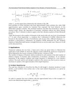
X/L=0.79 and 0.115, which are placed in convex and concave portion of the contraction,
respectively, the TI has relatively the highest reduction [3, 7]. Here, L is the length of the
contraction and X is from the beginning of the contraction.
The results by author in [3, 7] indicate that the installation of the trip strips has significant effects
on the TI in the test section of all four wind tunnels. The magnitude of reductions in the free
stream turbulence is affected by the positions of the trip strips. For one of wind tunnels, the
minimum TI is obtained when a trip strip with a diameter of 0.91mm is installed at X/L=0.79 or
in the wide portion of the contraction, at X/L=0.115, Fig. 2. Further, it is shown that the
installation of the trip strip in a suitable location not only reduces but also smoothes the
turbulence level. However, the zones between concave and convex region of the contraction,
that is at X/L=0.192 and 0.615, are not proper locations for trip strips. In general, one may
conclude that the TI in the test section of wind tunnels may be reduced to some degrees by
simply introducing trip strip with the right dimensions at the proper positions [3, 7].
Wind Tunnels and Experimental Fluid Dynamics Research
276
Fig. 11. Variation of TI with velocity at diameter of trip equal to 0.91mm for all various X/L
at center point, WT1 [7]
10. Conclusion
In this chapter, the role of turbulence in obtaining a spatially uniform steady stream of air
across and along the test section of wind tunnels considered. The study shows that the
turbulence has a major character in flow quality of wind tunnel and can excite
uncorrected results in experimental investigations of wind tunnels. Noise and eddy are
the sources of turbulence that must try to reduce them. Screens, honeycomb, high
contraction ratio and installation of trip strip at suitable portion of the contraction for
handling of gortler vortices and inflection type instabilities are useful for turbulence
reduction. Hot wire anemometry is a useful device for turbulence measurement that can
operate at frequency up to 100 kHz.
11. References
[1] White, F. M., “Viscous Fluid Flow”, 2nd ed., McGraw-Hill, New York, 1992
[2]
Bradshaw P., "The Understanding and Prediction of Turbulent Flow”, Engineering
Foundation Conference on Turbulent Heat Transfer, San Diego, 1996.
[3]
Dehghan Manshadi M., ‘‘A New Approach for Turbulence Reduction in a Subsonic
Wind Tunnel ’’, Sharif University of Technology, PhD Thesis, Tehran, Iran,
2009.
[4]
Burden T., "The First Few Lectures in a First Courses on Turbulence", Lecture Notes,
2008.
[5]
Hugh L. D., Ira H. A., “Reduction of Turbulence in Wind Tunnels”, NACA Technical
note, No. 1755, 1948.
[6]
Bell W. H., “turbulence vs drag-some future consideration”, Ocean Engng, Vol. 10, No. 1,
pp. 47-63, 1983.
The Importance of Turbulence in Assessment of Wind Tunnel Flow Quality
277
[7] Ghorbanian K., Soltani M. R., Manshadi M. D., "Experimental Investigation on
Turbulence Intensity Reduction in Subsonic Wind Tunnels", Aerospace science and
Technology,
Volume 15, Issue 2, March 2011, Pages 137-147.
[8]
Bruun, H .H . Hot-wire Anemometry, Oxford science publications, 1995.
[9]
Perry, A. E ., Hot-Wire Anemometry, Oxford, Clarendon, 1982.
[10]
Manshadi M. D., Keshavarz B., Soltani M. R., and Ghorbanian K., "An Innovative
Genetic Algorithm Approach for Direct Calibration of X-Probe Hot-wires",
Experimental Technique, doi:10.1111/j.1747-1567.2011.00705.x, 2011.
[11]
Manshadi M. D., Ghorbanian K., Soltani M. R., "Experimental Investigation on
Interaction between Turbulence and Sound in a Subsonic Wind Tunnel", ACTA
Mechanica Sinica, 26(4):531-539, 2010.
[12]
Uberoi, M. S., "Effect of wind-tunnel contraction on free stream turbulence"., J.
Aeronaut. Sci., 1956, 23, 754-764.
[13]
Mikhailova N. P., Repik E.U., Sosedko Y.P., "Optimal Control of Free Stream TI by
Means of Honeycombs", Fluid Dynamics, Vol. 29, No.3, 1994.
[14]
Scheiman J., Brooks J. D., “Comparison of Experimental and Theoretical Turbulence
Reduction from Screens, honeycomb, and Honeycomb-Screen Combinations”,
NASA Langley Research Center, 1981.
[15]
Mehta R. D., "Turbulent Boundary Layer Perturbed by a Screen", AIAA Journal, Vol.
23, No.9, 1985.
[16]
Schubauer G. B., Spangenberg, “Effect of Screens in Wide Angle Diffusers”, National
Advisory Committee for Aeronautics, Report 949, 1947.
[17]
Laws, E. M., Livesey, J.L., "Flow through Screens," Ann. Rev. Fluid Mech., 10, 247-266,
1978.
[18]
Derbunovich G. I., Zemskaya A. S., Repik E. U. and Sosedko P., "Effect of Flow
Contraction on the Level of Turbulence", Translated from Izvestiya Akademii
Nauk SSSR, No. 2, pp. 146-152, March-April, 1987.
[19]
Owen F. K., Stainback P.C., Harvey W.D., "Evaluation of Flow Quality in Two
NASA Transonic Wind Tunnels", Journal of aircraft, VOL. 18, NO. 6, JUNE
1981.
[20]
Wigeland R. A., Tanatichat J., Nagib H. M., "Evaluation of a New Concept for
Reducing Freestream Turbulence in Wind Tunnels", 11th Aerodynamic Testing
Conference, Paper No. 80-0432, 1980.
[21]
Soltani M. R., Ghorbanian K. and Manshadi M. D., "Application of Screens and Trips in
Enhancement of Flow Characteristics in Subsonic Wind Tunnels", International
Journal of Scientia Iranica, 17 (1), 2010.
[22]
Barlow J.B., and Rae, W.H, Pope A., “Low-Speed Wind Tunnel Testing", Third Edition,
John Wiley and Sons, 1999.
[23]
Ghorbanian K., Soltani M. R., Manshadi M. D. and Mirzaei M., "Control of
Separation in the Concave Portion of Contraction to Improve the Flow
Quality", the Aeronautical journal, Volume 113, Number 1141, pp 177-182,
March 2009.
[24]
Nishizawa A., Takagi S., Tokugawa N., Sobagaki T., "Rebirth of Turbulence in
Laminarized Boundary Layers along the Wind Tunnel Contraction ", 39th AIAA
Aerospace Sciences Meeting and exhibit,, AIAA 2001-0277, 2001.
Wind Tunnels and Experimental Fluid Dynamics Research
278
[25] Takagi S., Tokugawa N., Shiomi J. and Kohama Y., "Laminar Turbulent Transition
along the Contraction Nozzle in Subsonic flow", 37th AIAA Aerospace Sciences
Meeting and exhibit, Reno NV, 1999.
Part 2
Building Dynamics, Flow Control
and Fluid Mechanics
13
The Use of Wind Tunnel Measurements in
Building Design
Dat Duthinh and Emil Simiu
National Institute of Standards and Technology, Gaithersburg, Maryland,
United States of America
1. Introduction
The ASCE 7-10 Standard contains provisions on the use of the wind tunnel, but those
provisions are incomplete. For this reason estimates of structural response to wind can vary
significantly depending upon the laboratory that provides them. This has been the case, for
example, for New York City’s World Trade Center’s twin towers, for which such differences
have exceeded 40 % (NCSTAR 1-2, Appendix D, 2004). While the emphasis here is on the
testing of buildings in wind tunnels, it is therefore necessary to review the inter-related
elements involved in the estimation of the response of buildings to wind, namely,
micrometeorology, aerodynamics, similitude, wind climatology, statistics, and structural
reliability. The chapter also discusses the validation of wind tunnel measurements, and their
application to low-rise and tall buildings, and concludes with a description of a time-
domain method for designing structural members known as Database-Assisted Design. For
additional materials on wind tunnel testing the reader is referred to, e.g., ASCE (1999),
Reinhold (1982), and Simiu (2011).
2. Micrometeorology
Estimates of aerodynamic pressures and forces depend upon the features of the atmospheric
flow being adequately simulated in the wind tunnel. This section briefly reviews the
description of atmospheric flows affecting buildings and other structures in strong winds.
The description includes the characterization of mean wind profiles (Sect. 2.1) and of
atmospheric turbulence (Sects. 2.2-2.5).
2.1 The atmospheric boundary layer and the mean wind profile
Before the 1960’s aerodynamic tests of buildings were typically conducted in wind tunnels
with uniform flow. Later measurements were made in boundary-layer wind tunnels, thanks
to the influence of Jensen (1954), who rediscovered Flachsbart’s observation, made in 1932
(Flachsbart, 1932), that wind pressures in shear flows can differ markedly from
measurements in uniform flow. In this section we discuss the effects of the wind tunnel flow
features on the aerodynamic effects of interest.
The mean wind profile in horizontally homogeneous terrain can be described by the power
law, characterized by its exponent
α
that depends on terrain roughness (Hellman, 1916,
Davenport, 1965):
Wind Tunnels and Experimental Fluid Dynamics Research
282
(
)
(
)
=
(1)
where (
)and
(
)
are the wind speeds at elevations
and
. An alternative
description of the mean wind profile in horizontally homogeneous terrain is the logarithmic
law, characterized by the surface roughness length
:
(
)
=
∗
ln
(2)
Fig. 1. Meteorological wind tunnel, Wind Engineering Laboratory, Colorado State
University. Model and turntable are in the foreground, and spires are in the background
(courtesy of Professor Bogusz Bienkiewicz; photo by Gregory E. Stace).
The Use of Wind Tunnel Measurements in Building Design
283
where k ≈ 0.4,
∗
is the flow shear velocity, and
(
)
is the wind speed at elevation z. For
strong winds the applicability of the logarithmic law up to elevations of about 400 m has
been established theoretically by Csanady (1967) (for additional references and details see
also Simiu, 1973, Simiu & Scanlan, 1996) and by measurements in the atmosphere by Powell
et al. (2003). These results supersede the earlier belief (Davenport, 1965) that the logarithmic
law is valid for any wind speed up to about 50 m elevation. Typical values of z
0
range from 2
m to 0.005 m depending on the exposure category (Table C26.7-1, ASCE 7-10).
Over a rough floor, a tunnel length of 20 m to 30 m is required to develop a boundary layer of
0.5 m to 1 m (Marshall, 1984). To increase the depth of the boundary layer, wind tunnels make
use of passive devices such as grids, barriers, fences and spires (Fig. 1). In general, similitude
in the turbulence of air flows in the natural and the experimental settings is not achieved, even
for long wind tunnels, and especially for short (≈ 5 m) ones. Cermak (1982) discusses the flow
features downwind of a floor covered with different kinds of roughness elements.
Fig. 2. Wind speed profiles in simulations by wind tunnels participating in the Fritz et al.
(2008) comparison (Bienkiewicz et al., 2009). Open exposure refers to flat open country,
grasslands, and water surfaces, with scattered obstructions less than 9 m high. Suburban
exposure refers to wooded areas or other terrains with numerous, closely spaced single
family dwellings.
The various experimental set-ups used by various laboratories to simulate atmospheric
flows can result in fairly widely varying properties of the respective flows. Laboratories
that participated in an international comparison of wind tunnel estimates of wind effects on
low-rise buildings (Fritz et al., 2008) achieved mean wind profiles with power law
exponents
α
that varied between 0.139 and 0.191 (typical target value 1/7 = 0.143) and
between 0.165 and 0.234 (target value 0.22) for open and suburban exposures, respectively
(Bienkiewicz et al., 2009), see Fig. 2. These differences contributed to the significant
discrepancies among the respective values of the wind effects of interest.
Wind Tunnels and Experimental Fluid Dynamics Research
284
2.2 The turbulence intensity
The turbulence intensity I(z) at elevation z corresponding to the longitudinal flow
fluctuations (i.e., the fluctuations u(z) in the mean speed direction) is defined as the ratio
between the fluctuations’ root mean square and the mean wind speed U(z):
2
()
()
()
uz
Iz
Uz
=
(3)
Fig. 3. Turbulence intensities in simulations by wind tunnels participating in the Fritz et al.
(2008) comparison (Bienkiewicz et al., 2009).
Similar definitions hold for flow fluctuations in the lateral and vertical directions.
Longitudinal turbulence intensities achieved in flows simulated by six laboratories (Fritz et
al., 2008) exhibited strong variations, especially for suburban exposure (Fig. 3). For
structures with equivalent height of 10 m, I(z) ranges from 0.30 to 0.15 depending on the
exposure (ASCE 7-10 Sect. 26.9.4).
2.3 The integral turbulence length
The integral turbulence lengths of the longitudinal flow velocity fluctuations at a point are
measures of the average spatial dimensions of those fluctuations. Similar definitions hold
for the lateral and vertical flow fluctuations (see, e.g., Simiu & Scanlan (1996) for details).
The larger the turbulence scale, the larger is the building dimension affected by the
corresponding turbulent fluctuations. For example, a sufficiently large longitudinal integral
turbulence scale of the longitudinal turbulent fluctuations means that, if the flow is normal
to the windward face of a structure, those fluctuations can affect both its windward and
leeward faces. A large lateral scale of the longitudinal turbulent fluctuations means that
those fluctuations impinge almost simultaneously over a relatively large area normal to the
mean wind speed, resulting in correspondingly large longitudinal fluctuating wind loads.
The Use of Wind Tunnel Measurements in Building Design
285
2.4 The spectral density (or spectrum)
The spectral density (or spectrum) of the longitudinal velocity fluctuations provides a
measure of the strength of the fluctuations’ frequency components. It is a plot representing
the contributions of components with various frequencies to the variance of the fluctuations.
Similar definitions hold for lateral and vertical fluctuations. Note that the turbulence
intensity and the integral turbulence length are related to the spectral density. In practice the
spectra of the turbulent fluctuations cannot be reproduced in civil engineering wind tunnels
owing partly to the violation of the Reynolds number by several orders of magnitude, a fact
that prevents the simulation of high-frequency velocity fluctuations, and partly to the
difficulty of achieving large integral turbulence scales in the laboratory.
The Reynolds number is a measure of the ratio of inertial to viscous forces and is defined as:
=
=
(4)
where U is the velocity, L a typical surface dimension, the density, the viscosity and
the kinematic viscosity of the fluid (=
⁄
). Tennekes & Lumley (1964) suggest a Reynolds
number of the order of 10
5
to ensure the existence of an inertial subrange in the turbulent
flow generated in the wind tunnel. Turbulent velocity fluctuations can be represented by
eddies of various wavelengths, and the inertial subrange is the portion of the spectrum in
which eddy motion may be determined by the rate of energy transfer from larger eddies to
smaller ones independently of viscosity (Kolmogorov’s second hypothesis).
The cross-spectral density of longitudinal velocity fluctuations at two points is an
approximate measure of the degree of coherence between the respective fluctuations.
Similar definitions apply to lateral and vertical fluctuations. For small structures, (e.g., typical
homes) for which the turbulence length scales of interest are sufficiently large in relation to
the structure’s dimensions, the bulk of the fluctuating longitudinal wind speed components
may be assumed to be almost perfectly coherent over lengths comparable to the dimensions
of the structures’ exterior faces. This observation allows the use in the wind tunnel of flows
from which the low-frequency fluctuations present in the atmosphere are eliminated and are
replaced by an increment in the mean wind speed (Simiu et al., Fu et al., in press).
In addition to inducing resonant fluctuations in flexible structures, high-frequency turbulent
fluctuations have an important aerodynamic effect insofar as they transport across separation
layers particles with high momentum from zones outside the separation bubbles, thereby
promoting flow reattachment and affecting suctions in separation zones (Simiu & Miyata,
2006). Because, as was mentioned earlier, in commercial wind tunnels, the Reynolds
number is orders of magnitude smaller than at full scale, the viscous stresses within the
small (high-frequency) eddies of the laboratory flow are higher. The wind tunnel
counterparts of full-scale high-frequency fluctuations are therefore partly suppressed by
those stresses. This can affect significantly the extent to which laboratory and full-scale
suctions are similar, especially in flow separation regions where the suctions are strong.
Indeed, measurements have shown that, in zones of strong suctions, absolute values of
pressure coefficients are far lower in the wind tunnel than at full scale (Fig. 4).
2.5 Wind speeds as functions of averaging times
The relation between wind speeds averaged over different time intervals (e.g., the ratio between
wind speeds averaged over 3 s and wind speeds averaged over 10 min) varies as a function
of the time intervals owing to the presence of turbulence in the wind flow.
Wind Tunnels and Experimental Fluid Dynamics Research
286
Fig. 4. Pressure coefficients measured at building corner, eave level, Texas Tech University
Experimental Building (Long et al., 2006).
The flow characteristics discussed in Sections 2.1 through 2.5 depend to a significant extent
upon whether the storm to which the structure is subjected is of the large-scale extratropical
(synoptic) type, or a hurricane, a thunderstorm, a chinook wind, and so forth. In current
commercial practice the type of flow being simulated is the atmospheric boundary layer
typical of synoptic storms (straight line winds), and it is assumed that simulations in this
type of flow are adequate even if the structure is subjected to other types of storm.
In wind engineering practice it is important to remember that the parameters of any given
model of the wind flow are characterized by uncertainties in the sense that they can vary
from storm to storm. Such variability should be accounted for in any uncertainty analysis of
the wind effect estimates.
3. Aerodynamics and similitude
Although computational fluid dynamics has made tremendous progress in the last decade
thanks to high speed computing, its use has not reached routine level in the structural
design of buildings, and its predictions need to be verified by experiments. Wind tunnel
testing remains the primary tool for determining wind pressures on buildings. Aerodynamic
measurements can be performed simultaneously at large numbers of ports by using current
pressure measurement capabilities. The quantities of interest are primarily pressure
coefficients for mean pressures and for peak pressures (see, e.g., Fig. 4). This state of affairs
is changing, owing in part to approximate methods that replace low-frequency fluctuations
by increments in the mean speed, as discussed in Sect. 2.4.
The Use of Wind Tunnel Measurements in Building Design
287
Proper length scaling in boundary-layer wind tunnel requires:
=
(5)
where D is a characteristic length of the structure being tested, and subscripts m and p refer
to the model and the prototype respectively. L
x
is the longitudinal integral turbulence scale,
or length of the fluctuating longitudinal component of the wind speed. It is difficult to
produce large values of L
xm
in wind tunnels, and this can be a limiting factor for the size of
models testable in the laboratory.
As explained in the preceding section, it is in current practice desirable to ensure similitude
between prototype and model for the variations with height of mean speed and turbulence
effects, measured by turbulence intensities, integral scales, and spectral characteristics. The
following numbers are important in aerodynamics and scaling.
3.1 Reynolds number
Since flow separation occurs at sharp corners regardless of the value of the Reynolds
number, this phenomenon is assumed to be modeled correctly in a wind tunnel. Violation of
Reynolds number scaling, however, does affect the flow reattachment in long, bluff bodies,
and this affects the aerodynamic pressures. For curved bodies, the boundary layers at high
Reynolds number tend to be turbulent, and it is possible to generate approximately the same
behavior by roughening the surface of scaled models.
3.2 Froude number
The Froude number is the ratio of inertial to gravity forces:
=
(6)
where g is the acceleration of gravity. Take for example a model scaled at
=1 400
⁄⁄
.
Froude scaling requires
=1
√
400=1/20
⁄⁄
. The Reynolds number for the model is:
=
=
(
/)(
/)
=
(7)
Thus it is seen that Froude scaling and Reynolds scaling are incompatible if the laboratory
uses the same gravity constant and the same fluid (air) as the atmosphere.
3.3 Rossby number
The atmospheric boundary layer depth is proportional to the Rossby number R
o
:
=
(8)
where
c
.
.
ln(
⁄
)
,
=
()
,
U(h)
is the mean wind speed at a height h, z
0
is the
roughness length and f
c
is the Coriolis parameter. As the wind speed increases, so does the
boundary layer depth. For wind speeds of interest to the structural engineer, the boundary
layer is several kilometers deep. Most buildings are situated entirely in the lower one-tenth
of the boundary layer, where the longitudinal velocity spectrum
(
,
)
in the inertial
subrange can be expressed as:
Wind Tunnels and Experimental Fluid Dynamics Research
288
(,)
∗
=0.26
⁄
(9)
where n is the frequency of turbulent eddies, z the height,
∗
the shear velocity of the flow,
and =()
⁄
the Monin (or similitude) coordinate.
In a long wind tunnel, a boundary layer of the order of 1 m develops over a rough floor, and
the above equation only applies to the bottom 0.1 m. A 200 m tall building modeled to the
scale of 1/400 would only see its bottom 40 m exposed to the spectrum described by the
equation above.
3.4 Strouhal number
Vortex shedding is a regular phenomenon characterized by the Strouhal number:
=
(10)
where N
s
is the frequency of full cycles of vortex shedding, and D is a characteristic
dimension of the body normal to the mean flow velocity U.
3.5 Scaling effects of turbulent flow around bluff bodies
Davenport et al. (1977) compare wind pressure measurements for three models at scales of
1/500, 1/250 and 1/100. The prototype is a low-rise building 30.5 m x 24.4 m x 5.9 m with a
gable roof of slope 4.7 degrees. The ratios between corresponding measurements, in terms of
peak, mean and root-mean-square, differ significantly from unity in some instances and do
not follow any discernable pattern. For example, the ratio of the peak pressure of the 1/100
model to the 1/500 model measured at a roof corner is 1.34, and the ratio of the peak
pressure of the 1/250 model to the 1/500 model at the center of the long side is 0.63.
One reason for these discrepancies is the difficulty in determining the characteristic length
(integral scale) of turbulence at full scale (measurements can vary by a factor of five, even
ten), and in scaling this length to that of the model. In the investigation mentioned above
(Davenport et al., 1977), the integral scale of turbulence in the wind tunnel was estimated to
be 1/500 of its nominal value in atmospheric flow. Another possible reason for the
discrepancies is that the change in actual elevation of the corresponding measurement
points of the various models causes changes in turbulence intensities.
In the testing of rigid trussed frameworks, the effect of high-frequency turbulence components
may be assumed to be insignificant, since no flow reattachment can be expected to occur on
typical truss members, even in the presence of high-frequency turbulence fluctuations. Low-
frequency turbulence components may be assumed approximately to be perfectly coherent
over the width of vertical frameworks or the depth of horizontal frameworks. The tacit
acceptance of these assumptions explains why, even after the advent of boundary-layer wind
tunnels, aerodynamic testing of trussed frameworks has been performed in smooth flow
(Whitbread, 1980), i.e., flow with constant velocity and no significant turbulence fluctuations.
For bluff bodies with small dimensions (e.g., residential homes, or tributary areas of individual
portal frames in industrial buildings) this extreme simplification of the testing may not be
appropriate because high-frequency flow fluctuations can strongly influence test results.
3.6 Blockage
A structural model placed in the air flow provides partial blockage to the flow and causes it
to accelerate. Correction factors have been worked out for a limited number of
The Use of Wind Tunnel Measurements in Building Design
289
measurements and geometries. In general, for a blockage ratio of 2 %, the corrections are of
the order of 5 % and proportional to the blocking ratio (Melbourne, 1982).
4. Wind climatology
The wind tunnel method typically uses directional wind speed data whenever such data are
available. In some cases, directional wind speed observations are available for each of a
number of equally spaced directions, but for some of the directions the number of
observations is too small to allow meaningful estimates of the respective extremes. In those
cases a conservative assumption is required to construct appropriate sets of data for the
directions with insufficient observations by using data available for other directions. For an
example of such an assumption, see Grigoriu (2009).
5. Statistics of peak effects
In this section, we are concerned with the estimation of peak effects of a one-dimensional
stochastic process induced by a given wind speed. Such peak effects may pertain to
accelerations at the top of the structure, inter-story drifts, internal forces, and sums of
demand-to-capacity ratios used in interaction equations (e.g., the sum of (a) the ratio of the
axial force divided by axial force capacity and (b) the ratio of the bending moment divided
by the moment capacity). The estimation can take advantage of the fact that most wind
effects of interest are sums of many comparable randomly distributed contributions,
rendering those effects Gaussian. For this case simple, well-known techniques are available
for estimating the mean values of the peaks. If the wind effects of interest are not Gaussian
(this may be the case, e.g., for wind effects in low-rise buildings), techniques for estimating
statistics of their peaks are also available, see e.g., Sadek & Simiu (2002) or
www.nist.gov/wind, item III.
Two cases are of interest. The first case involves stochastic processes specified by their time
histories (i.e., in the time domain). For example, such a stochastic process may consist of the
internal force induced in a member by the sway responses in directions x and y. The peak
internal force of interest is then simply the peak of the sum of the internal forces associated
with the two sway responses. A similar simple summation yields the requisite peaks of
processes consisting of sums of any number of stochastic processes.
The second case involves stochastic processes specified by their spectral densities (i.e., in the
frequency domain). Such specification was and still is routinely used in wind engineering
dynamic analyses on account of the difficulty, up to the 1980s, of dealing computationally
with the solution of dynamic problems in the time domain. Obtaining the peak of a sum of
several stochastic processes is no longer possible by summing up those processes, because in
the frequency domain as used in typical wind engineering applications the phase
information inherent in the respective time histories is lost. Therefore the estimation of
peaks requires the use of sums of weighted component processes (e.g., axial forces and
bending moments), with weights specified by engineering judgment. As many as dozens of
such weighted combinations are prescribed to structural designers by wind engineering
laboratories, in an attempt to make sure that relevant peaks are not missed. This is time-
consuming from the point of view of the designer, as well as less accurate than the much
simpler, more transparent, and more effective time-domain approach. Additional
Wind Tunnels and Experimental Fluid Dynamics Research
290
drawbacks are the difficulty of accounting for wind directionality effects in a transparent
and physically meaningful way (see Simiu, 2011).
If wind directionality is not taken into account explicitly (i.e., other than through the use of a
blanket reduction factor, as is done in ASCE 7, 2006), then the mean recurrence intervals (MRI)
of a peak wind effect is simply assumed to be the MRI of the wind speed inducing it.
Estimation methods for extreme wind speeds with specified MRIs, regardless of their
direction, are discussed, e.g., in Simiu (2011). If directionality is explicitly accounted for in
the calculations, the peak wind effects with specified MRI are obtained as follows. Assume
the directional wind speed data consist of m sets (e.g., m storm events) of n directional wind
speeds each (corresponding to, e.g., n = 16, or n = 36 directions). For each of the m sets,
calculate the peak response induced by each of the n directional wind speeds, and retain
only the largest of these n responses. This yields a set of m largest peak responses. The m
peak responses are then rank-ordered. If the rate of arrival of the events associated with the
m sets is r/year, then the estimated MRI of a) the largest of the m peak responses is (m+1)/r
years; b) the p largest is (m+1)/(pr) years. This estimate is non-parametric.
In hurricane-prone regions, directional wind speeds in any specified number of storms are
typically obtained by Monte Carlo simulation using physical and probabilistic storm models
(e.g., Batts et al. 1980; Vickery & Twisdale, 1995; Vickery et al., 2009). If the size of an
existing database of hurricane wind speeds needs to be augmented (as may be necessary for
the only public hurricane wind speeds database that covers the entire Gulf and Atlantic
coasts of the United States, and contains 999 simulated storms for each station, listed on
www.nist.gov/wind), this augmentation can be achieved by using software developed by
Grigoriu (2009). For straight line (synoptic) and thunderstorm wind speed data, large sets of
simulated data and associated errors in their estimation can also be obtained using the
methods developed by Grigoriu (2009).
6. Structural reliability
The purpose of structural reliability is to develop design criteria assuring that the probability
of inadequate strength and serviceability performance is acceptably small. The traditional
approach to design, Allowable Stress Design (ASD), is no longer in use but is relevant for the
understanding of the Strength Design (SD) approach, currently specified in ASCE 7-10 (2010).
In its simplest form allowable stress design (ASD) achieves this purpose by requiring, for each
member, that the stress induced by the sum of the basic design loads not exceed the allowable
stress, typically defined as the nominal yield stress divided by a safety factor. The basic design
loads and the safety factor are based on experience gained in past practice. For example, the
basic design wind load is typically specified as the wind load with a nominal 50-yr MRI. If for
A36 steel (nominal yield stress 36 ksi or 249 MPa), the allowable stress for non-compact
sections is 22 ksi (152 MPa), then the safety factor is 36/22 = 1.64. ASD’s probabilistic content
consists of the specification of the MRI of the basic design wind load and of the definition of
the nominal yield stress as a specified percentage point of its probability distribution.
Strength design (SD) requires in its simplest form that, for each member, the stress induced by
the sum of the basic design loads, each multiplied by a load factor that depends upon the type
of load, not exceed the yield stress multiplied by a resistance factor smaller than unity.
Consider, for example, the case where wind is the only significant load acting on an A36 steel
member with non-compact cross section. The wind load factor specified by ASCE 7 is 1.6, and
if the resistance factor is 0.9, SD design requires that the basic wind load induce in the member
The Use of Wind Tunnel Measurements in Building Design
291
a stress of at most 36 x 0.9/1.6 = 20.25 ksi (139.6 MPa), rather than 22 ksi (151.7 MPa) as
required by ASD. In this example SD is more conservative than ASD. This is in part due to the
specification by ASCE 7 of a wind load factor equal to 1.6, even though the original intent of
the standard was to specify a wind load factor equal to 1.5 (see ASCE 7-05 Commentary Sect.
C6.5.4). Had the latter value of the wind load factor been specified, the SD would have
required that a stress of 36 x 0.9/1.5 = 21.6 ksi (148.9 MPa) not be exceeded under the basic
wind load, i.e., a stress substantially equal to the 22 ksi (151.7 MPa) stress required in ASD.
To see why the difference between ASD and SD can be significant, consider the case of a
member subjected to dead load and wind load. The uncertainties inherent in the wind load
being larger than those inherent in the dead load, it is appropriate that the safety margin
with respect to the loading (i.e., the load factor) be larger for the wind than for the dead
load. This is reflected in ASCE 7-05, Section 2.3, which specifies for the dead load factor a
value smaller than 1.5 or 1.6. In contrast, for ASD, the dead loads and the wind loads are
both affected by a factor equal to unity.(Reference to ASCE 7-05 is warranted in this section
for two reasons. First, ASCE 7-05 is still being widely used. Secondly, ASCE 7-10 provisions
on SD are based on the rationale inherent in the ASCE 7-05 SD provisions, in terms of
substance if not of format.)
The probabilistic content is richer for SD than for ASD inasmuch as the various load factors
account for estimated probability distributions of the total uncertainties, which include
uncertainties in the wind speed and in the wind effect.
Uncertainties in the wind speed. The design value may well be smaller than the actual value
affecting the structure during its life, since the wind speed is a random variable
characterized by a probability distribution. In addition, that distribution may be affected by
modeling errors (e.g., it could be a Type I Extreme Value distribution, a Type III Extreme
Value distribution, a penultimate distribution, a mixed distribution of synoptic and
thunderstorm wind speeds, and so forth). Finally, the assumed distribution and/or its
estimated parameters are affected by sampling errors due the relatively small size of the
observed data sample, by observation errors, and, in the case of hurricanes, by physical
modeling errors of climatological parameters used in Monte Carlo simulations of the wind
speeds, e.g., the radius of maximum wind speeds, the pressure defect at the center of the eye
of the storm, and so forth.
Uncertainties in the wind effect. Uncertainties in aerodynamic pressure or force coefficients are
due to measurement errors and/or to errors in the simulation of the flows that induce those
pressures. For rigid structures the responses induced by aerodynamic pressures are
proportional to the square of the wind speeds. For flexible structures the responses are
proportional to the wind speeds raised to powers larger than two. The contribution to errors in
the estimation of the wind response of estimation errors in the wind speeds is therefore greater
for flexible than for rigid structures. Another contribution is due to the effect of errors in the
estimation of natural frequencies of vibration, modal shapes, and damping ratios.
The wind load factor specified in ASCE 7 was estimated by accounting in an approximate
manner for the uncertainties in the wind speeds and wind effects affecting rigid structures in
non-hurricane wind climates. The resulting estimate was approximately 1.6 (or 1.5, depending
upon the version of ASCE 7 being considered). To simplify codification, the ASCE 7
conventional methods assume, for non-hurricane regions, that the MRI of the wind effect that
induces yield stresses is the MRI of the wind speed defined by the basic wind speed times the
square root of the wind load factor. Calculations based on simplifying assumptions described