Biomedical Engineering Trends in Electronics Communications and Software Part 19 pot
Bạn đang xem bản rút gọn của tài liệu. Xem và tải ngay bản đầy đủ của tài liệu tại đây (2.39 MB, 28 trang )
Biomedical Engineering Trends in Electronics, Communications and Software
710
W3C. Recommendation 10 webpage.
(2004, Febraury 10
th
). From: RDFS (RDF Vocabulary
Description Language 1.0: RDFS Schema) webpage
: />schema (last accessed: 2010, September).
W3C. Web Ontology Language Overview, W3C Recommendation webpage (2005, February 10th).
(last accessed: 2010,
September).
Walker, J., Pand, E., Johnston, D., Adler-Milstein, J., & Bates, D. a. (2005, January 19). The
Value of Healthcare Information Exchange and Interoperability. In:
Health Affairs,
Web Exclusive.
Wang, S W. et al. (2006). RFID Application in Hospitals: a Case Study on a Demonstration
RFID Project in a Taiwan Hospital. In:
Proc. of the 39th Annual Hawaii International
Conference on System Sciences (HICSS'06)
, 08, p. 184-194. Kauai, Hawaii (USA).
Weiser, M. (1991). The Computer for the 21st Century. In:
Scientific American - Special Issue on
Communications.
Williamson, J. JESS Wiki: Keep Your Rules Normalized. From:
JESS website:
(last
accessed: 2010, September).
0
Quality of Service, Adaptation, and Security
Provisioning in Wireless Patient Monitoring
Systems
Wolfgang Leister
1
,Trenton Schulz
1
, Arne Lie
2
Knut Grythe
2
and Ilangko Balasingham
3
1
Norsk Regnesentral
2
SINTEF
3
Interventional Centre, Oslo University Hospital
Dept. of Electronics & Telecommunications
Norwegian University of Science & Technology
Institute of Clinical Medicine, University of Oslo
1,2,3
Norway
1. Introduction
Modern patient monitoring systems are designed to put the individual into the centre of
the system architecture. In this paradigm, the patient is seen as a source of health-relevant
data that are processed and transferred. Patient monitoring systems are used in health care
enterprises as well as in paramedic, mobile, and home situations to foster ambient assisted
living (AAL) scenarios.
There are a multitude of standards and products available to support Quality of Service (QoS)
and security goals in patient monitoring systems. Yet, an architecture that supports these
goals from data aggregation to data transmission and visualisation for end user has not been
developed. Medical data from patient monitoring systems includes sampled values from
measurements, sound, images, and video. These data often have a time-aspect where several
data streams need to be synchronised. Therefore, rendering data from patient monitoring
systems can be considered an advanced form of multimedia data.
We propose a framework that will fill this QoS and security gap and provide a solution
that allows medical personnel better access to data and more mobility to the patients. The
framework is based on MPEG-21 and wireless sensor networks. It allows for end-to-end
optimisation and presentation of multimedia sensor data. The framework also addresses the
QoS, adaptation and security concerns of handling this data.
In Section 2 we present background on patient monitoring systems, their requirements and
how we envision communication is handled. We present communication systems in Section 3
and how to treat QoS in Section 4. A short introduction to data streaming, binary XML and
how they relate to patient monitoring systems is presented in Section 5. In Section 6 we our
proposed solution for the framework and present a security analysis of it in Section 7. Finally,
we offer our conclusions in Section 8.
36
2 Biomedical Engineering, Trends, Researches and Technologies
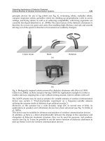
Fig. 1. Surgeons testing a patient monitoring system consisting of sensors, actuators, and
communication and presentation entities.
2. Patient monitoring systems
Patient monitoring systems comprise sensors, data communication, storage, processing, and
presentation of medical data. These functions are performed both near the patient, in local
surgery, or remotely at a health care infrastructure, e.g., a medical centre or a hospital. An
example of a patient monitoring system is shown in Fig. 1. In this figure, we see surgeons
holding some sensors and actuators. On the left side of the figure, a large monitor displays
the data from these devices. The information is also displayed on the laptop in the foreground
of the figure.
Patient monitoring systems can be used in a variety of health care scenarios ranging from
paramedic, diagnostic, surgical, post-operative, and home surveillance situations. The
systems must meet a high demand of flexibility since data may be produced outside a
health care enterprise. This requires specific measures in order to fulfil security, availability,
privacy, and QoS demands. The properties are: a) mobility; b) outside hospital infrastructure;
c) biomedical sensor networks in use; d) wireless channel.
As shown in a case study by Balasingham, Ihlen, Leister, Røe & Samset (2007), even within
or between health care enterprises, the requirements that applications need to meet are strict
and require specific measures or architectures. Data from patients are transferred through
networks to the health care enterprise, and made available in a suitable form to the medical
personnel to support the treatment of patients.
2.1 Communication levels
In order to account for the different health care scenarios, we propose the following levels
surrounding the patient in which data are processed and transferred, as outlined in Fig. 2.
These are divided into four levels — (0), (I), (II), and (III) — depending on the logical distance
712
Biomedical Engineering Trends in Electronics, Communications and Software
Quality of Service, Adaptation, and Security
Provisioning in Wireless Patient Monitoring Systems
3
to the patient with Level (0) being the patient. For Level (II), usually only one type applies at
a time. However, it must be possible to switch between the types in Level (II) as easily as the
patient moves between them.
(0) Patient. This is the actual patient.
(I) Personal sensor network. The personal sensor network denotes the patient and the
sensors measuring the medical data. These sensors are connected to each other in
a biomedical sensor network (BSN). While this sensor network can be connected
randomly, in most cases one special BSN node — typically one that has additional
power and computational resources — is appointed to be a personal cluster head (PCH),
where all data for one patient are collected. The PCH may have visualisation devices
attached to be used by the patient or by medical personnel. In this case, the PCH
represents all data for a patient. Other topologies are possible, including the possibility
that data from other patients are transferred using the sensor nodes of another patient’s
BSN. However, due to resource limitations of the sensor devices, organisational and
ethical issues may occur. Therefore, this possibility is disregarded.
(IIa) Paramedic. In the paramedic scenario, the BSN is connected to the medical devices
of an ambulance (car, plane, helicopter) via the PCH. The devices of the ambulance
can work autonomously, showing the patient status locally. Alternatively, the devices
of the ambulance can communicate with an external health care infrastructure, e.g.,
at a hospital. Note that the ambulance needs to employ some form of long-distance
communication to the external health care infrastructure.
(IIb) Smart home. The smart home scenario envisages that the patient is in a smart-home
environment, where the personal sensor network is connected to the infrastructure of
the smart-home. The smart home infrastructure might be connected to a health care
enterprise infrastructure using long-distance data communication.
(IIc) Mobility. The mobility scenario envisages that the patient is mobile, e.g., using public
or personal transportation facilities. The personal sensor network of the patient is
connected to the infrastructure of a health care enterprise via a mobile device, e.g., a
mobile Internet connection. Note that the mobile scenario requires temporary storage
in the PCH, since communication cannot be guaranteed at all times. The application
and the communication software must be aware of this.
(IId) Intensive care/surgery. During an operation the sensor data are transferred to the PCH
or directly to the hospital infrastructure over a relatively short distance. The sensors
are in a very controlled environment, but some sensors might be very resource limited
due to their size, so extra transport nodes close to the sensors might be needed. In
the operation environment, there is an increased need for QoS, so that correct data are
available to the surgeons at any time during the operation.
(IIe) Pre- and postoperative. During pre- and postoperative phases of a treatment, and for
use in hospital bedrooms, the sensor data are transferred from the sensor network to
the PCH, and from there to the health care information system.
(III) Health care information system. The health care information system is considered a
trusted environment. It comprises of the hospital network, the computing facilities,
databases, and access terminals in the hospital. It should be noted that communication
between Levels (II) and (III) is two-way.
713
Quality of Service, Adaptation, and Security Provisioning in Wireless Patient Monitoring Systems
4 Biomedical Engineering, Trends, Researches and Technologies
Fig. 2. Generic model of patient monitoring systems showing the data flow to the observer.
Each level may have one or more data observers. An observer can be either the patient, medical
personnel using a suitable terminal, or a processing unit that can trigger alarms, aggregate
data, create logs, etc. The observer is usually in Level (II), while the communication may, or
may not go through Level (III), depending on the application. The generic model in Fig. 2
helps identify where possible technology-transitions in the line of communication appear, as
well as where the levels of equal security requirements can be placed.
2.2 Medical data streams
The medical data in a patient monitoring system, regardless of which level it is in, form
streams of data which can be characterised as temporal multimedia data. These data streams
contain the sensor data, often sampled values, attached to time-stamps and meta data, such as
type and identification of the data streams. In most cases several separate streams of different
data are used to describe the situation of a patient at a given time interval. The data may also
contain triggers, alarms, and video data, as the capabilities of the sensor devices increase.
Multimedia data streams have a producer — here, the biomedical sensor — and a
consumer — here, a (mobile) terminal or a database. In principle, each data stream can be
transferred separately from the source (producer) to the sink (consumer). However, this
might be impractical for improvised situations since the assurance of requirements for QoS,
availability, security, and privacy will not be possible in a unified way. Therefore, we propose
to forward data in a standardised way, using the system model of a generic patient monitoring
system shown in Fig. 3.
This system model is suitable for patient monitoring systems where data from sensors are
transferred to an observer who retrieves these data using a terminal. The medical data may be
transferred to the health care information system to be stored and processed there. Additional
data from the health care information system may be used by the observer at a terminal
combined with the sensor data.
This generic system model divides the communication from Channels A to D as follows:
Channel A includes the sensor and the sensor network to the PCH, which acts as a gateway
for the personal sensor network to a network in Levels (IIa)–(IIe), also denoted as Level (II).
Channel A may involve several intermediate nodes employing both wireless or wired data
transfer. Channel B describes the channel from the PCH to the observer terminal, keeping the
communication in Levels (II), without going through the hospital infrastructure. Channel C
714
Biomedical Engineering Trends in Electronics, Communications and Software
Quality of Service, Adaptation, and Security
Provisioning in Wireless Patient Monitoring Systems
5
Fig. 3. System model of a generic patient monitoring system, identifying the communication
channels while the patient monitoring system transfers data.
transfers data from the PCH to the hospital infrastructure in Level (III) using infrastructure
like the Internet, a wired carrier or a wireless carrier. Channel D describes the data transport
from the hospital information system to the observer terminal in Level (II) using infrastructure
like the Internet, a wired carrier or a wireless carrier.
The generic system model in Fig. 2 shows the data flow to the observer in different health
care scenarios, while Fig. 3 shows the communication channels in such a system. In this
architecture, note that security functions, like establishing identities for authentication, might
use different channels in advance of the phase where the medical data are transferred. The
different phases are presented by Leister, Fretland & Balasingham (2009).
The generic model is not dependant on how the communication in the scenarios of Level (II)
are implemented. Channels C and D can have different characteristics depending on
the use case, i.e., whether an external (ambulance, mobility, smart home) or an internal
(hospital-related scenarios) source is used. Note also that Channel B can meet different
requirements, depending on the scenario. However, from a security perspective, a short-range
wireless channel is assumed.
Using the generic system model, we are able to treat the security challenges separately for
every channel, thus reducing the complexity of the security analysis. However, note that each
channel is implemented using several of the communication layers in OSI model.
In our framework, we intend to provide end-to-end streaming of medical sensor data as
depicted in Fig. 3: a) from the patient to the terminal of the medic via the PCH (using
Channels A and B); b) from the patient to the health care infrastructure (using Channels A and
C); and c) from the health care infrastructure to the terminal of the medic (using Channel D).
This also includes data streaming using Channels A, C, and D. The characteristics of these
channels vary with the scenario that is addressed.
In our concept, all medical data streams are expressed using the notion of the MDI, which in
some cases, e.g., in Channel A, may be expressed as μMDI (see Section 6).
3. Communication systems
In this section, we introduce wireless sensor networks and the need for providing quality
of service. We focus on the communication at Levels (I) and (II) since these are the
most interesting and are in contact with the patient. At each level, we can implement a
communications technology, such as ZigBee in Level (I); Bluetooth, WLAN, ZigBee or wires in
715
Quality of Service, Adaptation, and Security Provisioning in Wireless Patient Monitoring Systems
6 Biomedical Engineering, Trends, Researches and Technologies
Level (IIa); Bluetooth in Level (IIc), etc. Employing only one technology in each level makes it
easier to define and structure the security and QoS requirements. The medical data first must
traverse Level (I), then through Level (II), and possibly arrive at the hospital infrastructure,
before reaching the observer of the medical data, i.e., the medical personnel in Levels (II) or
(III). It is important to have well-defined interfaces between these levels as they need to be
technically implemented.
3.1 Wireless sensor networks
A wireless sensor network (WSN) is often a part of a patient monitoring system. In our
reference model shown in Fig. 3, the WSN is denoted as Channel A. The WSN consists of
base station receiving data from one or more tiny, low cost, low power sensor nodes that
monitor information. The sensors are clustered and relay information from other sensors that
may not be close enough to reach the base station.
A WSN is a good fit for a patient monitoring system since wireless technology is increasingly
used in the health care industry to help eliminate cables in patient monitoring systems. Here,
sensors can communicate wirelessly with a monitor that is close to the patient in a BSN. For
our purposes, a BSN can be considered a special case of a WSN. The WSN can contain many
small sensors that are capable of collecting vital signs and environmental information and
forwarding them along to the base station; the base station can then pass this information
onto the patient monitoring system. This leads, potentially, to more mobility for patients and
medical staff.
While a WSN can be used in many environments and situations — for example, R
¨
omer &
Mattern (2004) list applications that include herding and observing animals, checking the
movement of glaciers and ocean water, and military applications — the patient monitoring
systems have specific QoS and security requirements different from the other applications.
For example, medical data is considered private information and wireless communication
can be easily intercepted. This leads to issues in privacy, confidentiality and integrity. Also,
wireless networks have their own issues with quality of service and radio interference. In
addition, an attacker could alter the communication leading to threats for the patient.
The basic operations of a WSN are depicted in Fig. 4. The purpose of the deployment lies
in the observation, aggregating and reporting of events in a spatio-temporal process. The
communication strategies within a sensor node must support the occurrence of observed
process events in various parts of the network, and possibly using distributed signal
processing. Therefore, the nodes in a sensor node must cooperate to maximise the probability
to fulfil their deployed mission.
There are a variety of standard solutions that are used for communication between the nodes
on a wireless sensor networks. Depending upon the application and operational conditions,
the most suitable is selected. ZigBee and Bluetooth are two examples out of a growing set of
alternative solutions.
3.2 Quality of service provisioning
The observations made by the sensors are processed by suitable algorithms, possibly in a
distributed and collaborative fashion, before the results are conveyed from the WSN to the
users via a set of external networks. This way of approaching the operations of a WSN
resembles the traditional encoding and transmission of a single information source (Blahut,
1987), like voice in a mobile phone. The upper reference bound for QoS experienced by the
716
Biomedical Engineering Trends in Electronics, Communications and Software
Quality of Service, Adaptation, and Security
Provisioning in Wireless Patient Monitoring Systems
7
Fig. 4. Collaboration for information generation in a WSN and its transport to an external
user through the WSN and external network. S
0
is the node of origin and PCH represents the
patient cluster head.
user is the entropy of the source, while the delivered QoS is a result of the capabilities and
degradations induced by the chosen encoding and transmission capabilities.
An overview of QoS influential factors for sensor networks are presented and discussed by
Chen & Varshney (2004). These are organised into application- and network-specific factors,
with emphasis on the network. A middleware for supporting QoS in WSNs is introduced by
Heinzelman, Murphy, Carvalho & Perillo (2004) with examples from medical applications.
This middleware integrates the application and the WSN management to respond to the
required QoS and network lifetime. A protocol-independent QoS support for WSN is
presented by Troubleyn, De Poorter, Ruckebusch, Moerman & Demeester (2010) where the
packets between nodes are organised according to priority processing. The integration of a
WSN with external networks requires these two entities to be jointly considered (Khoshnevis
& Khalaj, 2007). The external transport mechanism must be mirrored in the WSN to make QoS
tradeoffs at this level. Similar aspects are also discussed by Patel & Jianfeng (2010).
Although many aspects of QoS in a WSN have been given in the literature, and solutions
for networks and signal processing exist, e.g., as presented by Lei & Heinzelman (2007), a
structured approach for organising and balancing the tradeoffs and degradation mechanisms
appears to be lacking. In the spirit of the layered QoS for IP and mobile networks (Bai,
Atiquzzaman & Lilja, 2006), we include, in the following section, the layered application QoS
stack presented by Grythe, Lie & Balasingham (2009). This stack organises and seperates the
degradation mechanisms within a WSN for the purpose of QoS trading between the various
layers. This layered approach also facilitates tradeoffs between the intra- and inter-WSN data
transport.
4. Application-oriented layered QoS stack for sensor network
The purpose of the WSN deployment lies in the observation and reporting of variables or
detecting events in a spatio-temporal process as indicated in Fig. 4. As such, the overall QoS to
be evaluated should be oriented towards the application and end-user. The QoS experienced
by the user is a result of degraded maximum theoretical information content in the event area.
717
Quality of Service, Adaptation, and Security Provisioning in Wireless Patient Monitoring Systems
8 Biomedical Engineering, Trends, Researches and Technologies
The QoS degradation is due to both deployed topology and algorithmic imperfections under
interaction with communication imperfections both internally and externally to the WSN.
The operations of a WSN and associated systems can be split into five different actions:
(1) Carry out the process observation by the distributed sensor nodes, each doing individual
measurements.
(2) In the case of distributed signal processing, enable the nodes to collaborate under the
framework of the implemented algorithms.
(3) Based upon the operations of the algorithms, the nodes finally reach a consensus called a
result instance. This may be either periodically or a more random time domain operation.
(4) The result instance is transmitted to the user, initiated by a random or predetermined
sensor node called the node of origin, S
0
.
(5) The result instance is presented to the user via a terminal.
4.1 Layered QoS stack
The communication strategies within a sensor node must support the occurrence of observed
process events in various parts of the network and possibly distributed signal processing.
Therefore, the nodes in a sensor network must cooperate to maximise the probability
of meeting their deployed mission. The four-layered QoS stack of Fig. 5 simplifies the
organisation of the degradation tradeoffs. Generally, the user perceptual QoS evolution
between the layers behave as
QoS
En
≥ QoS
Dep
≥ QoS
Eff
≥ QoS
InTrans
≥ QoS
ExTrans
= QoS
UserInput
where the QoS subscripts indicate which layer they belong to. This equation of inequalities
reflects that the available user experience — or perception of QoS—is decreasing through the
WSN towards the user. Examples of metrics representing the user QoS are variances, signal to
noise ratio (SNR) for source coding or detection probabilities for event detections. QoS metrics
are derived from the specific application, representing the most proper quality criterion.
For a given WSN implementation and a given QoS metric q , the evolution of at the various
levels of the layered model can be expressed as:
⎡
⎢
⎢
⎢
⎢
⎣
q
En
q
Dep
q
Eff
q
InTans
q
ExTrans
⎤
⎥
⎥
⎥
⎥
⎦
=
⎡
⎢
⎢
⎢
⎢
⎣
10 0 0
b
1
00 0
0 b
2
00
0
0
0
0
b
3
0
0
b
4
⎤
⎥
⎥
⎥
⎥
⎦
⎡
⎢
⎢
⎣
q
En
q
Dep
q
Eff
q
InTans
⎤
⎥
⎥
⎦
or more compact as:
q
= Bq
U
where q contains all the layer metrics while q
U
contains the process and intra-WSN metrics.
Associating q
0
≡ q
En
and q
4
≡ q
ExTrans
, the QoS evolution is logically expressed in a product
form as:
q
n
= q
0
n
∏
i=1
b
i
; n = 1:4
This expression reflects the QoS interactions and tradeoff levels of Fig. 5. Due to the statistical
behaviour of the influential mechanisms, as discussed later, the parameters in the matrix B
718
Biomedical Engineering Trends in Electronics, Communications and Software
Quality of Service, Adaptation, and Security
Provisioning in Wireless Patient Monitoring Systems
9
Fig. 5. The application oriented layered QoS stack for sensor networks and its association
with the external network.
represent random variables, p
(b); b ≡
{
b
1
,b
2
,b
3
,b
4
}
. Their values and quantification range
depends upon the chosen metrics. Defining
f
(b
n
)=
n
∏
i=1
b
i
; n = 1:4
the mean value of the associated value of the quality metric is expressed within the variable
domain D
(b
n
) as:
E
(q
n
|q
0
)=q
0
D(b
n
)
f (b
n
)p(b
n
)db
n
As is demonstrated later, for a specific application and implemented algorithm in the WSN, it
is possible that not all layers are relevant.
There are many mechanisms that influence each of the four levels. We discuss a few of them
below.
Level QL0 — Entropy. The Entropy level represents the maximum theoretical information
content of the spatio-temporal process (STP) in the case of feature extraction
(Youngchul, Poor & Heejung, 2009; Blahut, 1987) or the optimum event detection
performance given the properties of the STP (Trees, 1968; Viswanathan & Varshney,
1997). These features are only related to the STP and not to any specific deployed
algorithm or communication solution. As such, QL0 represents the upper performance
and information bound a user can expect from the STP.
Level QL1 — Deployment. This level represents the spatial sampling of the STP performed
through the topology of the specific deployed WSN and the associated implemented,
possibly distributed, signal processing algorithm. Given these factors, a definition of
the best performance can be done assuming that all the samples from all the sensor
nodes are collected and processed in a centralised unit without transport time delays or
errors. This is the maximum QoS a user or users can expect from the given WSN and
719
Quality of Service, Adaptation, and Security Provisioning in Wireless Patient Monitoring Systems
10 Biomedical Engineering, Trends, Researches and Technologies
does not depend upon the communication properties within or external to the WSN.
The algorithm may produce a single result instance, a limited set or a continuous time
discrete stream of results. In the following, we denote one quantified result as a result
instance.
Level QL2 — Efficiency. Efficiency denotes the QoS degradation due to interaction between
the nodes in the area of event (see Fig. 4) when executing the algorithm to obtain
a result instance and how this contributes to the QoS. The factors involved may be
divided into topology-related and communication-influenced. Topology-related factors
include node malfunction, distributed energy consumption and saving while examples
of communication-influenced factors are packet loss, bit error rate (BER), variable
delays and capacity. As discussed by Bai et al. (2006); Lei & Heinzelman (2007) and
others, there are several factors influencing the networking within a WSN. Cross-layer
optimisation and energy efficiency are key factors in this context.
Level QL3 — Transport. Once the implemented algorithm produces a result instance, this is
conveyed from a node of origin — S
0
in Fig. 4 — to the external user via intra-WSN
transport and the external network. S
0
may be a fixed node or an appointed node
during the algorithmic interaction. In Fig. 5, QL3 is split into QL3I and QL3Ex to
separate the internal and external transport mechanisms respectively. The typical
transport degradation mechanisms are delay and packet loss in addition to broken
intra links due to nonfunctional nodes. Since the interaction with the external network
occurs at QL3, this layer implicitly involves the issue of optimising this interaction
to balance the transport QoS degradation. In the single user case, a single external,
possibly heterogeneous, network is involved; with multiple users, many different
external networks are possible. The transport cost functions and packet losses are
factors influencing this interaction. In some cases with small losses (Khoshnevis &
Khalaj, 2007), the intra- and inter-transport may be treated separately. Otherwise, a joint
optimisation is necessary involving the transport statistics of all the networks, including
the intra-WSN transport.
4.2 Application examples
We give three examples of signal processing in a WSN to illustrate the involvement of the
different QoS layers. We apply the QoS measure at the algorithmic level and not at an
information theoretical level. The latter is reflecting the STP properties.
Single sensor and one parameter. The observation is performed with one senor node. A time
series,
{
z
m
;m ∈ Z
+
}
, is generated and the samples are transmitted to the user, possibly
via multiple hops, in the WSN. Here S
0
is also the sampling node. The reconstruction
quality of the sequence by the user is governed by the QoS layers QL0, QL1, QL3I and
QL3Ex. If the node is malfunctioning in this case, no information is conveyed and QL2
is influential. A proper algorithmic user QoS metric may be the minimum mean square
error (MMSE):
MMSE
≡ E
(z
m
−z
User
m
)
2
Uniform STP and sum aggregation. We assume that a WSN with K nodes is deployed in the
STP area and that the area of event is the whole STP area, i.e., A
Event
= A
STP
. We want
720
Biomedical Engineering Trends in Electronics, Communications and Software
Quality of Service, Adaptation, and Security
Provisioning in Wireless Patient Monitoring Systems
11
to calculate the spatial mean value given by the aggregation function
E
(z
m
)=
1
K
K
∑
k=1
z
k
m
= γ
m
If the PCH node is identical to the node S
0
, the layers involved are QL0, QL1, QL2 and
QL3Ex since there is no intra-transport of the final result instants
{
γ
m
}
. Again MMSE
is a proper user QoS metric.
Collaborative information processing (CIP). The nodes within A
Event
is carrying out a CIP.
In this case, a set of nodes use their observations and collaborate to generate a set of
result instances at each time instance m. In other words:
{
Y
m
}
⇒
CIP
ˆ
X
m
As can be seen in Fig. 4, for a deployed CIP in an event area, all the layers are
contributing to the end-user QoS result. In this case, the MMSE is also applicable as
an objective user QoS metric.
4.3 Local versus global optimisation
In the context of WSN for medical applications and the described variability in user terminal
capabilities and heterogeneous external networks, proper QoS to each terminal is critical.
Elements within a WSN influencing the QoS are briefly described by Chen & Varshney (2004).
The operations of the network are governed by two modes: event reporting or queries from
users. For proper operation of a medical WSN with respect to QoS and energy efficiency,
external users are divided into two groups: super users and application users. Super users
have access to both the PCH (Patient Cluster Head) and individual bidirectional nodes of the
WSN. They can tune parameters and the performance of the WSN or initiate a deep network
data query. Application users can only access the PCH and obtain streaming data from the
PCH or members of parameter sets stored in the PCH. This distinction is necessary to avoid
draining energy due to excessive queries and to control the access to the sensor nodes.
The general description presented previously expressed the QoS evolution in a product form
as:
q
n
= q
0
n
∏
i=1
b
i
; n = 1:4
This can be considered as an expression pointing towards a single user representation or a
representation for multiple users as U
≡
u
j
; j = 1:J
in the situation where all the external
networks are identical. If the performance of the external networks are randomly varying or
are a mix of different solutions as with heterogeneous networks, the QoS evolution for each
individual user u
j
∈ U can be expressed as q
j
= b
j
4
· Q
0
, where the internal operations of the
BAN is represented by
Q
0
= q
0
3
∏
i=1
b
i
The performance trade-offs between the internal and external behaviour of the WSN to obtain
the wanted or expected user QoS can be analysed and evaluated through these mechanisms.
A comment that is valid for both QL2 and QL3 is that when multiple disjoint observations
areas within the WSN are active simultaneously, the wireless communication activities may
721
Quality of Service, Adaptation, and Security Provisioning in Wireless Patient Monitoring Systems
12 Biomedical Engineering, Trends, Researches and Technologies
create mutual interference. Also note that a similarly layered QoS structure can be used in the
situation where an actuator in a WSN is fed with an excitant signal from an external user or
control algorithm.
Such a layered QoS modelling resembles the data processing theorem (Blahut, 1987)
stating that, in a cascade of signal processing elements, no processing can increase mutual
information. The statement puts no limit on the sophistication or complexity of the individual
cascaded processing blocks.
5. Data streaming
Typically, sensor data are streamed from the source to the sink, i.e., the sensor data are
consumed, e.g., presented on a terminal, while new data from the same stream are arriving;
an exception might be sensors that transfer single still images on demand. For data
streaming, several standards have been developed covering certain properties. Relevant
Internet protocol standards include the transport protocol RTP/RTCP (Schulzrinne, Casner,
Frederick & Jacobson, 2003) and session protocols like SDP (Handley, Jacobson & Perkins,
2006) and RTSP (Schulzrinne, Rao & Lanphier, 1998). Relevant media compression standards
include ISO MPEG 2 Systems (ISO/IEC 13818) and MPEG 4 Systems (ISO/IEC 14496). Media
content searching, filtering and transactions include MPEG 7 (ISO/IEC 15938) and MPEG-21
(ISO/IEC 21000).
The DICOM standard (DICOM, 2008), which is the basis for Picture Archive and
Communication Systems (PACS), is not designed to support streaming of medical data. Some
research has begun to add support for streaming (Dragan & Ivetic, 2009), but this is still in the
preliminary stages. On the other hand, DICOM is well suited of storing and retrieving sensor
data in a health care environment. So, it should be possible to import and export to DICOM.
5.1 MPEG-21
MPEG-21 (Burnett, Pereira, de Walle & Koenen, 2006) is a standard from the International
Standards Organisation (ISO) that attempts to define a complete infrastructure for delivery
and consumption of multimedia content. The effort was started in 2000. The ISO’s
introduction to Part 1 of the standard summarises the vision as, “ to define a multimedia
framework to enable transparent and augmented use of multimedia resources across a wide
range of networks and devices used by different communities” (International Standards
Organisation, 2004, page vii). MPEG-21 currently consists of 18 parts that cover diverse issues
such as defining the fundamental structures, adapting these structures between different
networks, specifying creator’s and user’s rights, and defining testbeds and conformance
suites.
The basic unit for data in MPEG-21 is the digital item (DI). Like many other parts of MPEG-21,
it is defined in XML to be machine readable. The DI is a generic item that can contain
components, resources, or other containers. These structures can either refer to other XML
structures, included data, or reference another item by a universal resource identifier (URI).
Additional parts of MPEG-21 include how to uniquely identify an item and how to process
them.
MPEG-21 defines two ways of streaming information. One is by using Binary XML that was
originally part of MPEG-7, but is included as Part 16 of MPEG-21. Part 18 defines digital item
streaming (DIS), which is a pure XML way of streaming.
Another goal of MPEG-21 is to ensure that creators can protect their creations and that users
of content have the correct rights for viewing them. Parts 4, 5, and 6 of the standard deal with
722
Biomedical Engineering Trends in Electronics, Communications and Software
Quality of Service, Adaptation, and Security
Provisioning in Wireless Patient Monitoring Systems
13
these issues. It defines the rights — Rights Data Dictionary (RDD), how to express the rights
in a machine readable form — Rights Expression Language (REL), and finally, how they are
enforced — Intellectual Property Management and Protection (IPMP).
Since the vision is that MPEG-21 is to be used in a variety of situations, MPEG-21 defines Part
7 — Digital Item Adaptation — for specifying how streams (i.e., the media content) should be
adapted to suit different network and terminal characteristics, like bandwidth and display
resolution. This is a vital mechanism in order to maximise the perceived QoS given the
constraints of the network and observer equipment.
5.2 Binary XML
One of the issues with using wireless sensor networks is that the sensors cannot transfer much
data in each individual packet. For example, earlier specifications of ZigBee restrict the total
packet size to 128 bytes including routing information. Later versions of ZigBee allow for
larger sizes, but that is dependent on the hardware in use (Daintree Networks, Inc., 2010). So,
the size of the data in each packet is important. Since MPEG-21 uses XML throughout, we
need to use Binary XML to compress this.
Binary XML refers to any specification which defines the compact representation of the
Extensible Markup Language (XML) in a binary format (Bray, Paoli, Sperberg-McQueen,
Maler, Yergeau & Cowan, 2006). While there are several competing formats, none has been
accepted as a standard yet. Using a binary XML format reduces the size and eases parsing
of the documents at the cost of human-readability. Binary XML is used in applications where
performance or resource limitations apply. As part of this, we do not consider traditional
compression methods applied to XML documents, such as using gzip, or an existing standard
like ASN.1.
There are several different implementations of binary XML. For example:
– The Fast Infoset standard from the ISO and International Telecommunications Union (ITU)
(International Standards Organisation, 2007b)
– The Extensible XML Interchange format from the World Wide Web Consortium (W3C)
(Schneider & Kamiya, 2009; Peintner & Pericas-Geertsen, 2009)
– The Binary MPEG format for XML (BiM) defined by the ISO (International Standards
Organisation, 2006) and is used by many ETSI standards for Digital TV and Mobile TV
There are also other binary XML formats that are defined for specific application domains.
We selected the Binary MPEG XML Format (BiM) and Efficient XML Interchange (EXI) as the
most promising candidates since these were designed to work with general purpose XML,
and because it was possible to get access to implementations of both.
BiM is part of the MPEG-7 standard (International Standards Organisation, 2006) and is also
part of MPEG-21 (Part 16). It specifies a general method for compressing and decompressing
XML documents for efficient transport and storage. It does this by examining the schemas for
the document and using that information to create a separate decoder header that is used for
encoding and decoding documents that use those schemas. The encoder uses this information
to encode and partition the document into fragments. These fragments are then sent to the
decoder. The decoder reassembles the fragments into a semantically similar document.
EXI comes from the W3C. Its purpose is to have a “. very compact, high performance XML
representation that was designed to work well for a broad range of applications,” (Schneider
& Kamiya, 2009). It currently is a W3C Candidate Recommendation. EXI is schema informed,
which means that it can use the schema to create a more efficient document, but a schema is not
723
Quality of Service, Adaptation, and Security Provisioning in Wireless Patient Monitoring Systems
14 Biomedical Engineering, Trends, Researches and Technologies
necessary. EXI is compatible with other documents at the XML Information Set level, but not
at the XML syntax level. This means that you can inter-operate with other XML documents
assuming that you have everything at the Information Set level (2009). EXI does not have
explicit support for fragmenting itself, instead it depends other XML technologies for this.
Ignoring the separate BiM decoding header, both EXI and BiM compress documents to
comparable sizes. Therefore, other criteria were needed to figure out which method would
be used. One obvious advantage that BiM has over EXI is its support for fragmentation and
streaming. The BiM standard (International Standards Organisation, 2006) goes into detail
about how BiM can be fragmented and reassembled, while EXI (Schneider & Kamiya, 2009)
only describes that EXI fragments can exist, but not how a document could be fragmented,
streamed or reassembled.
6. Proposed solution
We have experimented with a variety of different solutions and have come up with some
solutions that integrate both WSN and MPEG-21 into patient monitoring systems. As the
basic idea, we adapt MPEG-21 to a WSN by adapting the basic Digital Items and employing
binary XML.
6.1 MPEG-21 for patient monitoring systems
MPEG-21 includes features like adaptation and security for network and users that make
it a good candidate in a health care system architecture. However, most of the patient
data aggregators are based on wireless sensor networks containing nodes with restricted
capabilities and battery capacity. This means that they may not be able to run all of the
processor intensive tasks of MPEG-21. Therefore, the MPEG-21 standard needs to be adapted
to work with this restricted setup.
As mentioned in Section 5.1, a digital item (DI) is the basic unit for transferring information.
Land
´
en (2003) introduces a medical digital item (MDI) that adapts the digital item to the health
care sector. The MDI also encapsulates mechanisms for adaptation and security. Since sensors
have limited resources, we developed a lightweight MDI or μMDI for the sensors. However, to
save battery capacity and processing power in some situations, the XML syntax of MPEG-21
is not employed at all.
Lie, Grythe & Balasingham (2008) present a hospital scenario where the use of digital item
adaptation (DIA) is designed for sensors wirelessly connected to a PCH. The PCH is connected
to the health information system. The medical personnel access the patient data using a
terminal with an MPEG-21 enabled browser. After a threat analysis of patient monitoring
systems (Leister, Abie, Groven, Fretland & Balasingham, 2008) we extended this architecture
to include (BSNs) (Leister, Fretland & Balasingham, 2008). The architecture supports security,
privacy, and authentication, by using the mechanisms of MPEG-21 in the OSI presentation
layer and a carefully designed μMDI (Leister et al., 2009). It also supports content adaptation
according to terminal and network capabilities, QoS, energy efficiency, and several types of
session mobility. The impact of this work is currently being studied in a recently developed
testbed for evaluating MPEG-21 in health care applications, which is described in Section 6.4.
Other approaches to using MPEG-21 in health care use the IPMP Part of MPEG-21 for
patient records (Brox, 2005). Recently, a framework for using MPEG-21 IPMP components
for a security framework for pervasive health care architectures has been presented by
Fragopoulos, Gialelis & Serpanos (2009), including wireless communication between personal
724
Biomedical Engineering Trends in Electronics, Communications and Software
Quality of Service, Adaptation, and Security
Provisioning in Wireless Patient Monitoring Systems
15
digital assistants (PDA). While that work introduces MPEG-21 for medical applications, our
work includes the use of MPEG-21 for BSN and uses a generic model to analyse the threats.
6.2 Using binary XML
The initial plan was to use BiM since we could partition up a document into fragments,
compress it, and send it all with one tool. EXI would only give us the compression. Ultimately,
the final decision came down to the quality of implementations that were available since we
did not have time nor resources to create our own implementation. The BiM implementation
(Technische Universit
¨
at M
¨
unchen, 2007-2008) seems to be incomplete, is not documented, and
has many bugs. Initially, it would not encode our μMDI document at all. After a lot of tracing
and fixing, we were able to get it to encode a document similar to μMDI, but it then failed
to decode it correctly. It also seems to be missing the code for partitioning the document into
fragments and reassembling it.
By contrast, the EXI implementation (EXIficient) is available as an open source project
(Peintner, 2010). While it is missing some documentation, it is actively developed and seems
to handle all the situations we have given it. Since EXI has no built in streaming, we needed
a method for streaming the items. This was solved using MPEG-21 Part 18 — Digital Item
Streaming.
Digital Item Streaming (DIS) works by specifying a separate XML document that defines the
Bitstream Binding Language (BBL) for a document. This BBL specifies the packets or packet
streams for the document, when these packets should be sent, and how the source document
should be divided up. The BBL is then used by software to divide the document up and
send it over arbitrary protocols. DIS also allows specifying constraints for packet streams
(such as number of items, or packet size), but the standard indicates that constraints will be
broken in order to send a packet. There is a publicly available implementation from the ISO
(International Standards Organisation, 2007a). that works well. One issue with DIS is that
it only works with with a “completed” document. That is, one cannot add siblings to the
document after you have sent over the basic skeleton. Future packets must be children of the
current elements.
6.3 The complete system
We combine μMDI, EXI, and DIS to form the following solution for a BSN using MPEG-21.
We have expanded the μMDI to contain multiple entries. A portion of the new μMDI can be
seen in Fig. 6. The various sensors can then send their identification information and their
data as separate packets using DIS. These packets are eventually received by the base station
and are attached to an already existing skeleton document. This document has a limited
number of parts. After this document is done, a new skeleton is added and the sensor can
then retransmit its identity and continue sending its information. The base station can transfer
this information on to the patient monitoring system.
The resulting packets should be small, but we can further reduce their size by using EXI and
transmitting them. The base station will receive the items as an EXI stream and will apply
them to the XML document.
The packets are sent from the WSN to a PCH. The PCH takes the information and converts
it from a μMDI to a real MDI, adds extra information (e.g., identifying information for
the patient), and sends the information to other communication levels. This information is
encrypted with strong encryption, ensuring that only medical staff with correct permissions
may use it.
725
Quality of Service, Adaptation, and Security Provisioning in Wireless Patient Monitoring Systems
16 Biomedical Engineering, Trends, Researches and Technologies
<did:DIDL xmlns:did="urn:mpeg:mpeg21:2002:02-DIDL-NS"
xmlns:xsi=" />xmlns:dii="urn:mpeg:mpeg21:2002:01-DII-NS"
xsi:schemaLocation="urn:mpeg:mpeg21:2002:02-DIDL-NS schemas/didl.xsd
urn:mpeg:mpeg21:2002:01-DII-NS schemas/dii.xsd">
<did:Container>
<did:Item id="myitem">
<did:Descriptor>
<did:Statement mimeType="text/xml">
<dii:Identifier>urn:grid:a1-abcde-9873216540-f</dii:Identifier>
</did:Statement>
</did:Descriptor>
<did:Descriptor>
<did:Statement mimeType="text/xml">
<dii:Type>urn:sensor:bloodpressure</dii:Type>
</did:Statement>
</did:Descriptor>
<did:Item>
<did:Descriptor>
<did:Statement mimeType="text/plain">20</did:Statement>
</did:Descriptor>
<did:Component>
<did:Resource mimeType="text/plain">68.300</did:Resource>
</did:Component>
</did:Item>
<did:Item>
Fig. 6. Excerpt from a μMDI document adapted for Digital Item Streaming (DIS)
6.4 MPEG-21 testbed
A proposed architecture’s performance and functionality is best verified using a dedicated
software testing platform. Thus, a Java-based testbed was created to test the hospital and
home-care networks. The testbed is based on an existing MPEG-21 software that was
developed during the MPEG-21 standardisation work (Perkis & Drege, 2008), and then
modified to support the aforementioned medical network requirements (Lie et al., 2008). The
testbed design requirements had the following architecture in mind:
726
Biomedical Engineering Trends in Electronics, Communications and Software
Quality of Service, Adaptation, and Security
Provisioning in Wireless Patient Monitoring Systems
17
Fig. 7. The hospital network architecture envisioned for the MPEG-21 supporting testbed
(Lie et al., 2008).
– Support for wireless medical sensors
– PCH bed-side terminals (optionally compatible with the NCAP — Network Capable
Application Processors — architecture of the IEEE 1451 standard) (IEEE1451.0, 2007;
IEEE1451.5, 2007), including WSN radio interface and WLAN radio interface
– WLAN APs and backbone network infrastructure
– User terminals equipped with MPEG-21 browsing capabilities
– An MPEG-21 Broker server (MB)
– One or several media servers (MS)
– Optional Media resource Adaptation Server (MAS)
The envisioned system is depicted in Fig. 7. The medical body sensors are communicating
with the bed-side PCH terminal. This PCH includes NCAP functionality in case IEEE 1451.5
is in use, and uses short-range radio systems to communicate with the active sensors (e.g.,
Zigbee). Thus, the PCH will collect all the necessary meta information regarding the sensor
capabilities and current status collected in MPEG-21 validated XML DIs, based on the IEEE
1451 TEDS (Transducer Electronic Data Sheets). In addition, there must be a dedicated
authentication procedure to ensure that new sensors are connected to the intended PCH (the
short-range radio coverage can reach other patients sensors and PCH). The principle of the
resurrecting duckling (Stajano & Anderson, 1999) with physical imprinting between the sensor
nodes and correct PCH is a viable authentication approach for exchanging symmetric secret
keys.
All PCH terminals are connected to the network infrastructure, e.g., using WLAN. This helps
minimise the traffic from the energy constrained sensors. A moving patient without a PCH
would call for frequent handovers between the sensors and different access points.
To facilitate easy retrieval of all information available, a few centralised servers are needed.
The media broker (MB) server will hold the MPEG-21 CDI (Content Description Items) that
gives the updated menus on the end-users terminals, e.g., regarding patient lists. Patient
and diagnosis search could be facilitated through the accompanying MPEG-7 standard and
underlying meta information. Each patient will have one dedicated CDI menu system for its
PCH and one for the Electronic Patient Record (EPR) system, holding all relevant EPR and
pre-stored medical media. When pre-stored media is selected, it will be retrieved from the
media streaming server (MS). An optional powerful adaptation server (MAS) can be used to
727
Quality of Service, Adaptation, and Security Provisioning in Wireless Patient Monitoring Systems
18 Biomedical Engineering, Trends, Researches and Technologies
Fig. 8. The Java based MPEG-21 testbed architecture.
facilitate media format adaptation on-the-fly for both live and pre-stored media, following
MPEG-21 Part 7 methodology (DIA — Digital Item Adaptation).
The observer will thus use the system via the terminal, e.g., an MPEG-21 capable browsing
terminal, to access both live content streamed via the PCH, and pre-stored content from
the MS. The MPEG-21 testbed also incorporates support for Session Mobility (Soma, 2007).
The testbed is programmed in Java and ECMAscript, and has MPEG-21 validated XML
files that format the graphical user interface menus with the supported functionality. In
addition to supporting session mobility and DIA, it uses the MPEG-21 DIP — Digital Item
Processing — engine to process the user activities. For example, to process media streaming it
activates a Java based player named Fobs4JMF, which consists of Sun Java Media Framework
(JMF) player enhanced with codecs from the open source package ffmpeg (Omnividea, 2008).
Fig. 8 shows a diagram with the key software components. At top, the user terminal is shown.
The initial GUI is formed by the local root DID (smdid.xml in this example). From this GUI
the user can select the patient list CDI located at the MB. After selecting a specific patient, the
user can choose either PCH or EPR. If choosing the PCH, the terminal will be given access over
HTTP to the online PCH for this patient. This PCH contains the current CDI showing a list
of connected wireless sensors (cdi
pch.xml). The user will now be able to access online
data such as ECG. Available media format choices are stored in dedicated XML files (the
728
Biomedical Engineering Trends in Electronics, Communications and Software
Quality of Service, Adaptation, and Security
Provisioning in Wireless Patient Monitoring Systems
19
Fig. 9. Snapshots from the MPEG-21 testbed, observer terminal part: a) start screen with
selection of source, b) The GUI is generated given the CDI contents, where the observer can
select the particular content, and c) the rendering of the selected medical content.
oval object at figure mid bottom). The available media formats are checked against the UED
(Usage Environment Descriptions) information, and a DIA engine located in the PCH or at a
centralised MS or MAS would eventually adapt the content for optimal fidelity to the user’s
terminal. Finally a message will be sent to the terminal containing the URL to the possibly
adapted media stream.
In Fig. 9, an example walkthrough of the user terminal functionality is displayed. The user
selects a specific PCH, using IP address and path to CDI. The list of medical content described
in this particular CDI is used to generate the GUI presented to the user. Behind the scenes, the
selected content is adapted to the current display capabilities and network conditions, using
the DIA functionality on the UED information.
7. Security analysis
In this section, we perform a security analysis of the use of MPEG-21 in patient monitoring
systems. The security requirements for patient monitoring systems are given by Leister
et al. (2009) as the following: (a) availability, (b) data confidentiality, (c) data integrity,
and (d) data authenticity. The general threats and attacks to these security objectives are
eavesdropping, denial of service, masquerading, and disclosure. Leister et al. identified the
threats associated to these factors as compromised, destroyed, malfunctioning, lost or stolen
components; software errors; misuse of emergency access; and denial of service attacks for the
components; compromised or unstable communication infrastructure; and eavesdropping on
the communication channels.
We consider these security goals separately for each of the levels introduced earlier in
Section 2.1. This allows us to consider separately the threats and remedies for security, and
also consider whether the particular component or channel of a patient monitoring system
is within a trusted environment. Components and channels in a trusted environment can be
considered secure. For components and channels outside a trusted environment, we consider
the threat model by Dolev & Yao (1981), where an attacker can overhear, intercept, and
synthesise any message, and is only limited by the constraints of the cryptographic methods
used. Since some of the devices used may not have the resources for strong cryptographic
methods, the assumption of the Dolev-Yao attacker might be not applicable in all situations,
729
Quality of Service, Adaptation, and Security Provisioning in Wireless Patient Monitoring Systems
20 Biomedical Engineering, Trends, Researches and Technologies
and additional measures might be necessary, especially when wireless sensor networks are a
part of the patient monitoring system.
Using the Dolev-Yao threat model, availability cannot always be guaranteed since an attacker
always can synthesise messages, and thus disturb or interrupt a channel. While this cannot
be prevented on the OSI application layer using MPEG-21, there might be other technical
measures on lower OSI layers that can be applied, such as spread spectrum technologies.
The development of radio access methods based on time-hopping and frequency-hopping
spread-spectrum (TH/FH-SS) addresses power-efficient signaling methods, which becomes
an interesting candidate for wireless sensor networks. TH/FH-SS is preceived as an
anti-jamming technique with low complexity and does not require complicated signal
processing. An example of their implementation can be found in Bluetooth systems (Tsai
& Chang, 1994; Salonidis et al., 2005). However, these technologies are beyond the scope of
this chapter.
Some threats and vulnerabilities can be addressed on an administrative level, such as
describing responsibilities for the stakeholders, educating personnel, or providing routines
for keeping devices out of the hands of adversaries. These non-technical routines are not
considered further in this context.
Due to the nature of the biomedical data, we consider a model where a numbered sequence
of unique data packets that are on a channel are transferred from source to sink, protected
by means of MPEG-21. When this data stream arrives, packets may have been lost, altered,
replayed, be out of order, be subject to eavesdropping, be stored, etc. These characteristics
may be the result of processes at lower OSI layers.
In patient monitoring systems, data are usually sent in packets using both connection-based or
connectionless channels. Connectionless channels do not offer retransmission automatically.
However, mechanisms for retransmissions on any channel might block sending of data, and
thus prohibit the timely transfer of data. Ideally, short, self-contained sequences of packets
are preferred to avoid the issues in retransmission.
For Level (0) the security considerations are limited to human communication patterns, such
as outlined in the communication theory by Watzlawick, Beavin & Jackson (1967). The
other levels can be considered more from a technical perspective, while both technical and
administrative means can be used to reduce the vulnerabilities.
7.1 Security considerations for level (I)
Level (I) is usually implemented as a wired or wireless, biomedical sensor network, where
most of the data traffic consists of a stream from the sensor node to the sink since we are not
considering actuator networks here. Leister et al. (2009) discuss threats for biomedical sensor
networks in the domains of the entity domain, the network domain, the specific protocol
domain, and the routing and forwarding domain. In these domains, an adversary who has
access to the medium, can eavesdrop, inject, delete and alter data packets. This can lead to
incorrect data, lost data, data being attached to the wrong data stream or patient, and inferior
service quality.
Eavesdropping obviously threatens confidentiality and privacy goals. Lost, delayed, and
altered packets threaten the integrity and the authenticity of the data as well as the availability.
As a consequence, this could cause inappropriate, delayed or missing treatment of the patient
at the risk of damage to the patient’s health.
MPEG-21 does not solve threats arising at the lower communication layers, but is suited to
detect possible inconsistencies in the case of altered content so that wrong content can be
730
Biomedical Engineering Trends in Electronics, Communications and Software
Quality of Service, Adaptation, and Security
Provisioning in Wireless Patient Monitoring Systems
21
marked or discarded. Regarding eavesdropping, MPEG-21 offers mechanisms to encrypt the
content. Digital Items can be identified in MPEG-21, thus facilitating that the data belong to
the correct stream and patient as long as the data source can be authenticated. Authentication
is done by using the identification tags on the data and encryption. Therefore, as long as the
encryption key is secret, the authentication will work. The initialisation procedure of sensor
nodes shown by Leister et al. (2009) guarantees this. Here, the sensor nodes are provided
with the necessary security credentials in the initialisation step, while these are used in the
operation mode.
In wireless sensor networks, the data streams from the sensor to the PCH can be sent via other
nodes. These nodes do not possess the capabilities to decrypt the streams from another sensor
node, and cannot inject valid packets, or alter packets consistently. However, data aggregation
in the sensor network is not possible in such a scenario.
Due to resource constraints in the devices, the possible cryptographic methods that can be
applied are weak. Therefore, additional measures must be taken, such as restricting all
data that can identify a patient in the wireless sensor network. The identifying information
necessary to attach the data to the right patient must therefore be formed such that the patient
is not revealed.
The architecture by Leister et al. suggests that the software loaded into the sensor nodes is
tied together with the necessary credentials for encryption and authentication. Therefore,
once provided with the credentials, the software in the sensor node cannot be altered unless
exchanged entirely, which would be similar to an attacker providing a fake node.
7.2 Security considerations for level (II)
Compared to Level (I), there are less resource restrictions for the scenarios on Level (II).
Therefore, better cryptographic methods can be applied, and the restriction on not sending
identifying information is less important. The health care infrastructure can perform data
aggregation if necessary, and also convert the μMDI to an MDI with data not available in the
sensor network. Note, however, that identifying information should not be sent in the channel
unless necessary. For other characteristics, the same mechanisms apply regarding the use of
MPEG-21.
When roaming between the Levels (IIa) to (IIe) the authentication mechanism beyond
MPEG-21 is responsible for establishing the trust to facilitate the communication between the
PCH and the entity responsible for the respective level or scenario by using the correct keys.
Note that in some scenarios the PCH can have the role of both.
7.3 Security considerations for level (III)
Devices that are in the hospital infrastructure and that can be authenticated are considered
secure, and not tampered with; for these devices, no specific measures are necessary.
However, note that authentication is always necessary. In Level (III), the use of MPEG-21
provides a unified method to represent the medical data, and to provide data confidentiality,
data integrity, and data authenticity through the mechanisms used.
7.4 Security considerations end-to-end
While MPEG-21 can be used to provide the security goals from end-to-end, other standards
might be employed in a health care enterprise, such as DICOM, ELIN XML (Christensen,
2009) or HL7 (Shaver, 2007), and make data conversions necessary for the data to be stored or
731
Quality of Service, Adaptation, and Security Provisioning in Wireless Patient Monitoring Systems
22 Biomedical Engineering, Trends, Researches and Technologies
processed. The representation of medical data in a MDI data structure provides the security
goals of confidentiality, data integrity, and data authenticity.
Since being placed in the presentation layer, MPEG-21 can be used in the Levels (I)-(III) and
end-to-end to sustain the security goals. Functionalities of the presented architecture, such
as converting the μMDI to MDI, are not necessarily performed by the PCH, i.e., Level (I),
but can be performed in Level (II) or (III), before being further processed and stored. The
end-to-end security is sustained as long as the entities processing MPEG-21 can be trusted,
and the cryptographic methods used are strong enough.
The architecture shown here addresses the threats of devices being tampered with,
eavesdropping, altered communication at several layers, in the sense that wrong data are
not accepted. The limitations are in the relatively weak encryption in the sensor nodes. An
adversary could eavesdrop on the traffic, break the encryption, and either introduce a fake
node, or use an attack at the wireless network level. This is not considered by the Dolev-Yao
attacker, but could be done in a practical case.
However, since the wireless communication using weak encryption is limited to Level (I)
where the communication range is limited, an adversary needs to have access to the vicinity
of the patient, or have access to communication credentials from the inside. Such threats need
to be addressed on an administrative and stakeholder level, e.g., by strict control of access
to areas where security is critical, rules for handling devices, measures to increase awareness
among medical personnel, and so on.
The Dolev-Yao attacker sets requirements on the encryption. However, this is problematic
due to limited resources in the sensors. Therefore, to avoid the risk that an attacker can get the
data to the right patient, we do not include data into the stream that can be used to identify the
patient, such as a personal identification number. The identity establishment must be done by
routines using the mechanisms described by MPEG-21.
The security analysis shows that the communication in patient monitoring systems can be
secure in principle in relation to the mentioned security goals and threats. For a concrete
implementation, a formal analysis is necessary, where the involved protocols are modelled,
and formally analysed using tools such as those shown by Hagalisletto, Strand, Leister &
Groven (2009) in another application area. The same methods can be applied for patient
monitoring systems, using concrete implementations and protocols.
8. Conclusion
We have shown a framework that includes QoS, adaptation, and security provisioning for
wireless patient monitoring systems with an emphasis on a solution that integrates the patient
monitoring system into the hospital infrastructure. For this, we proposed an architecture that
uses the MPEG-21 standard to reach these goals. We implemented parts of the system in a
testbed to show that the architecture is viable, and gained practical results.
We found that MPEG-21 is suitable for integrating a biomedical WSN with the health care
infrastructure in different health care scenarios. Challenges arising from the scarce resources
generally available in WSN are addressed by utilising XML compression, XML streaming,
and architectural means that avoid handling XML data in its text form in the sensor nodes.
One issue that remains is what should be part of the metadata in a digital item (DI) and what
should be implemented in the DI adaptation engine.
We showed that security concerns can be covered by describing the scenarios and considering
the different communication levels and communication channels. However, the WSN
has scarce resources that result in weak cryptography and the communication medium is
732
Biomedical Engineering Trends in Electronics, Communications and Software
Quality of Service, Adaptation, and Security
Provisioning in Wireless Patient Monitoring Systems
23
accessible; the result is that not all threats can be stopped at the OSI presentation level.
Therefore, in the case of certain attacks by a man in the middle, the availability might be
reduced. Adaptation for a patient monitoring system is shown by the means of a testbed that
also shows the integration with the information system of the healthcare enterprise.
While MPEG-21 covers security and adaptation issues, the QoS requirements are addressed
in WSN by a stack-oriented approach using a degradation model in an optimisation process.
How to implement these QoS structures in MPEG-21 is not investigated. However, it appears
that the adaptation engine approach is more versatile than editing metadata, and permits a
wider range of dynamic QoS attributes to be supported.
Future work on the architecture includes more integration and implementation on a larger
scale to determine how we can adjust parameters so the architecture is suitable for a real
network. These consideration about the architecture and its parameters are important
for factors like power — thus battery life of sensors — achievable security, availability, and
flexibility in the form of adaptation.
In the future, this work can lead to benefits for both the health care workers and patients.
Using our architecture, patients are able to move around more freely, stay productive out of
a hospital environment and know that their medical data is secure. At the same time, health
care workers have a better overview of a patient’s medical data in a variety of environments
and are assured of a certain level of QoS. The result is that, in the eventuality that a patient
needs it, treatment can arrive in a timely manner.
9. Acknowledgements
This research is funded by the SAMPOS and WISENET projects in the VERDIKT framework
of the Norwegian Research Council.
10. References
Bai, H., Atiquzzaman, M. & Lilja, D. J. (2006). Layered view of QoS issues in IP-based mobile
wireless networks, Int. Journal on Comm. Systems 18: 141–161.
Balasingham, I., Ihlen, H., Leister, W., Røe, P. & Samset, E. (2007). Communication of medical
images, text, and messages in inter-enterprise systems: A case study in Norway, IEEE
Transactions on Information Technology in Biomedicine 11(1): 7–13.
Blahut, R. E. (1987). Principles and practice of information theory, Addison-Wesley Longman
Publishing Co., Inc., Boston, MA, USA.
Bray, T., Paoli, J., Sperberg-McQueen, C. M., Maler, E., Yergeau, F. & Cowan, J.
(2006). Extensible Markup Language (XML) 1.1 (second edition), World Wide Web
Consortium, Recommendation REC-xml11-20060816.
Brox, G. A. (2005). MPEG-21 as an access control tool for the national health service care
records service, Journal of Telemedicine and Telecare 11 Suppl 1: 23–5.
Burnett, I. S., Pereira, F., de Walle, R. V. & Koenen, R. (eds) (2006). The MPEG-21 Book, John
Wiley & Sons. ISBN 0-47001011-8.
Chen, D. & Varshney, P. K. (2004). QoS support in wireless sensor networks: A survey, 2004
International Conference on Wireless Networks (ICWN 2004).
Christensen, T. (2009). Sluttraport ELIN, Sluttrapport, Den norske legeforening, Pb. 7000 St.
Olavs plass, NO-0130 Oslo, Norway. In Norwegian.
Daintree Networks, Inc. (2010). Zigbee specification comparison matrix. Last accessed
September 2, 2010, />733
Quality of Service, Adaptation, and Security Provisioning in Wireless Patient Monitoring Systems