Recent Advances in Wireless Communications and Networks Part 2 doc
Bạn đang xem bản rút gọn của tài liệu. Xem và tải ngay bản đầy đủ của tài liệu tại đây (2.31 MB, 30 trang )
Recent Advances in Wireless Communications and Networks
20
iii. A phase noise caused by thermal noise and inter-symbol interference that is uniformly
distributed from
π
−
to
π
.
Fig. 7. Comparison of the variance of the two algorithms with that of the MCRB
Fig. 8. Feed-forward NDA
The estimation variance has been derived (Bellini, 1990) in a scenario with a very high SNR,
the estimation variance can be approached as
A Study of Cramér-Rao-Like Bounds and Their Applications to Wireless Communications
21
2
22 2
0
31
/
2(-1)
D
f
s
EN
TLL m
σ
π
≈ (71)
The MCRB in this case is
()
3
3
0
31
()
/
2
D
s
T
MCRB f
EN
LT
π
= (72)
Thus, when 1L and 1m
=
,the algorithm performance will attain the MCRB. However,
this result is obtained under very high SNR. Further research is needed to design estimators
that can approach or attain the estimation bounds with less restriction.
7. References
Bellimi, S., Molinari, C. and Tartara, G. (1990). Digital Frequency Estimation in Burst Mode
QPSK Transmission, IEEE Trans. Commun., Vol.38, No.7 , (July 1990), pp. 959-961,
ISSN: 0090-6778
Cramer, H. (1946). Mathematical Method of Statistics, Princeton University Press, ISBN-13:
978-0691005478, Uppsala, Sweden.
D’Andrea, A. N., Mengali, U. and Reggiannini, R. (1994). The Modified Cramer-Rao Bound
and Its Application to Synchronization Problems, IEEE Trans. Commun., Vol.42,
No.2/3/4, (Febuary 1994), pp. 1391-1399, ISSN: 0090-6778
Gini, F. and Reggiannini, R. (2000). On the Use of Cramer-Rao-Like Bounds in the Presence
of Random Nuisance Parameters, IEEE Trans. Commun., Vol.48, No.12, (December
2000), pp. 2120-2126, ISSN 0090-6778.
Gardner, F. M. (1986). A BPSK/QPSK Timing Error Detecor for Samples Receivers, IEEE
Trans. Commun., Vol.34, No.5, (May 1986), pp. 423-429, ISSN: 0090-6778
Jesupret, T., Moeneclaey, M. and Ascheid, G. (1991). Digital Demodulator Synchronization,
ESA Draft Final Report, ESTEC No. 8437-89-NL-RE., (Febuary 1991)
Kay, S. M. (1998). Fundamentals of Statistical Signal Processing, Prentice Hall, ISBN 0-13-
345711-7, Upper Saddle River, New Jersey
Kobayashi, H. (1971). Simultaneous Adaptive Estimation and Decision Algorithm for
Carrier Modulated Data Transmission Systems, IEEE Trans. Commun., Vol.19, No.3,
(June 1971), pp. 268-280, ISSN: 0018-9332
Kotz, S. and Johnson, N. L. (1993). Breakthroughs in Statistics: Volume 1: Foundations and Basic
Theory, Springer-Verlag, ISBN: 0387940375, New York.
Lin, J. C. (2003). Maximum-Likelihood Frame Timing Instant and Frequency Offset
Estimation for OFDM Communication Over A Fast Rayleigh Fading Channel, IEEE
Trans. Vehic. Technol., Vol.52, No.4, (July 2003), pp. 1049-1062.
Lin, J. C. (2008). Least-Squares Channel Estimation for Mobile OFDM Communication on
Time-Varying Frequency-Selective Fading Channels, IEEE Trans. Vehic. Technol.,
Vol.57, No.6, (November 2008), pp. 3538-3550.
Lin, J. C. (2009). Least-Squares Channel Estimation Assisted by Self-Interference
Cancellation for Mobile PRP-OFDM Applications, IET Commun., Vol.3, Iss.12,
(December 2009), pp. 1907-1918.
Recent Advances in Wireless Communications and Networks
22
Mueller, K. H. and Muller, M. (1976). Timing Recovery in Digital Synchronous Data
Receivers, IEEE Trans. Commun., Vol.24, No.5, (May 1976), pp. 516-530, ISSN: 0090-
6778.
Miller, R. W. and Chang, C. B. (1978). A Modified Cramer-Rao Bound and its Applications,
IEEE Trans. On Inform. Throey, Vol.IT-24, No.3, (May 1978), pp-389-400, ISSN : 0018-
9448
Poor, H. V. (1994). An Introduction to Signal Detection and Estimation, Springer-Verlag, ISBN:
0-387-94173-8, New York.
Viterbi, A. J. and Viterbi, A. M. (1983). Nonlinear Estimation of PSK-Modulated Carrier
Phase with Application to Burst Digital Transmission, IEEE Trans. Inform. Throey,
Vol.IT-29, No.3, (July 1983), pp. 543-551, ISSN : 0018-9448.
2
Synchronization for OFDM-Based Systems
Yu-Ting Sun and Jia-Chin Lin
National Central University, Taiwan,
R.O.C
1. Introduction
Recently, orthogonal frequency division multiplexing (OFDM) techniques have received
great interest in wireless communications for their high speed data transmission. OFDM
improves robustness against narrowband interference or severely frequency-selective
channel fades caused by long multipath delay spreads and impulsive noise. A single fade or
interferer can cause the whole link to fail in a single carrier system. However, only a small
portion of the subcarriers are damaged in a multicarrier system. In a classical frequency
division multiplexing and parallel data systems, the signal frequency band is split into N
nonoverlapping frequency subchannels that are each modulated with a corresponding
individual symbol to eliminate interchannel interference. Nevertheless, available bandwidth
utilization is too low to waste precious resources on conventional frequency division
multiplexing systems. The OFDM technique with overlapping and orthogonal subchannels
was proposed to increase spectrum efficiency. A high-rate serial signal stream is divided
into many low-rate parallel streams; each parallel stream modulates a mutually orthogonal
subchannel individually. Therefore, OFDM technologies have recently been chosen as
candidates for fourth-generation (4G) mobile communications in a variety of standards,
such as 802.16m and LTE/LTE-A.
2. OFDM fundamentals
2.1 System descriptions
The block diagram of an OFDM transceiver is shown in Fig. 1. Information bits are grouped
and mapped using M-phase shift keying (MPSK) or quadrature amplitude modulation
(QAM). Because an OFDM symbol consists of a sum of subcarriers, the thn
−
1N × mapped
signal symbol
n
X is fed into the modulator using the inverse fast Fourier transform (IFFT).
Then, the modulated signal
n
x can be written as
1
2
0
1
, 0,1, , -1
N
jknN
nk
k
xXenN
N
π
−
=
==
∑
(1)
where N is the number of subcarriers or the IFFT size, k is the subcarrier index,
n is the
time index, and
1 N is the normalized frequency separation of the subcarriers. Note that
n
x
and
k
X form an pointN − discrete Fourier transform (DFT) pair. The relationship can be
expressed as
Recent Advances in Wireless Communications and Networks
24
{}
1
2/
0
1
DFT , 0,1, , - 1
N
jknN
nNn k
k
XxxenN
N
π
−
−
=
== =
∑
(2)
Fig. 1. The block diagram of the OFDM transceiver
The data symbol
k
X
can be recovered approximately by using a DFT operation at the
receiver if the orthogonality of the OFDM symbol is not destroyed by intersymbol
interference (ISI) and intercarrier interference (ICI). A cyclic prefix (CP) is used in an OFDM
system to prevent ISI and ICI. The CP usually repeats the last
L
samples of an OFDM block
and then is arranged in front of the block. The resulting symbol
n
s can be represented as
, , 1, , 1
, 0,1, , 1
Nn
n
n
xnLL
s
xn N
+
=
−−+ −
⎧
=
⎨
=−
⎩
(3)
The transmitted signal may pass through a channel h depending on the environments. The
receiver signal
n
r can be written as
nn
rs hw
=
⊗+ (4)
where
w
denotes the additive white Gaussian noise (AWGN). The data symbol
n
Y can be
recovered by using a DFT operation and is determined as
1
2
0
1
, 0,1, , -1
N
jknN
nk
k
YyenN
N
π
−
=
==
∑
(5)
Fig. 2 (a) shows the spectrum of an OFDM subchannel, and (b) shows an entire OFDM
signal. At the maximum value of each subcarrier frequency, all other subcarrier spectra are
null. The relationship between the OFDM block and CP is depicted clearly in Fig. 3.
The OFDM technique offers reliable effective transmission; however, it is far more
vulnerable to symbol timing error and carrier frequency offset. Sensitivity to symbol timing
offset is much higher in multicarrier communications than in single carrier communications
because of intersymbol interference. The mismatch or instability of the local oscillator
inevitably causes an offset in the carrier frequency that can cause a high bit error rate and
performance degradation because of intercarrier interference. Therefore, the unknown
Synchronization for OFDM-Based Systems
25
OFDM symbol arrival times and mismatch/instability of the oscillators in the transmitter
and the receiver are two significant synchronization problems in the design of OFDM
communications. A detailed description of symbol timing error and carrier frequency offset
is given in the following sections.
-6 -4 -2 0 2 4 6
-0.4
-0.2
0
0.2
0.4
0.6
0.8
1
Frequency
-6 -4 -2 0 2 4 6
-0.4
-0.2
0
0.2
0.4
0.6
0.8
1
Frequency
(a) (b)
Fig. 2. Spectra of (a) an OFDM subchannel and (b) an OFDM signal
Fig. 3. An OFDM symbol with a cyclic prefix
2.2 Synchronization issues
2.2.1 Timing offset
OFDM systems exploit their unique features by using a guard interval with a cyclic prefix to
eliminate intersymbol interference and intercarrier interference. In general, the symbol
timing offset may vary in an interval that is equal to the guard time and does not cause
intersymbol interference or intercarrier interference. OFDM systems have more robustness
to compare with carrier frequency offset. However, a problem arises when the sampling
Recent Advances in Wireless Communications and Networks
26
frequency does not sample an accurate position; the sensitivity to symbol timing offset
increases in OFDM systems. Receivers have to be tracked time-varying symbol timing offset,
which results in time-varying phase changes. Intercarrier interference comes into being
another attached problem. Because an error in the sampling frequency means an error in the
FFT interval duration, the sampled subcarriers are no longer mutually orthogonal. The
deviation is more severe as the delay spread in multipath fading increases; then, the tolerance
for the delay spread is less than the expected value. As a result, timing synchronization in
OFDM systems is an important design issue to minimize the loss of robustness.
2.2.2 Carrier frequency offset
In section 2.1, it is evident that at all OFDM subcarriers are orthogonal to each other when
they have a different integer number of cycles in the FFT interval. The number of cycles is
not an integer in FFT interval when a frequency offset exists. This phenomenon leads to
intercarrier interference after the FFT. The output of FFT for each subcarrier contains an
interfering term with interference power that is inversely proportional to the frequency
spacing from all other subcarriers (Nee & Prasad, 2000). The amount of intercarrier
interference for subcarriers in the middle of the OFDM spectrum is roughly twice as larger
as that at the OFDM band edges because there are more interferers from interfering
subcarriers on both sides. In practice, frequency-selective fading from the Doppler effect
and/or mismatch and instability of the local oscillators in the transmitter and receiver cause
carrier frequency offset. This effect invariably results in severe performance degradation in
OFDM communications and leads to a high bit error rate. OFDM systems are more sensitive
to carrier frequency offset; therefore, compensating frequency errors are very important.
3. Application scenarios
The major objectives for OFDM synchronization include identifying the beginning of
individual OFDM symbol timing and ensuring the orthogonality of each subcarrier. Various
algorithms have been proposed to estimate symbol timing and carrier frequency offset.
These methods can be classified into two categories: data-aided algorithms and non-data-
aided (also called blind) algorithms. By using known training sequences or pilot symbols, a
data-aided algorithm can achieve high estimation accuracy and construct the structure simply.
Data-aided algorithms require additional data blocks to transmit known synchronization
information. Nevertheless, this method diminishes the efficiency of transmission to offer the
possibility for synchronization. Non-data-aided (blind) algorithms were proposed to solve
the inefficiency problem of the data-aided algorithm. Alternative techniques are based on
the cyclic extension that is provided in OFDM communication systems. These techniques
can achieve high spectrum efficiency but are more complicated.
In the data-aided technique, several synchronization symbols are directly inserted between
the transmitted OFDM blocks; then, these pilot symbols are collected at the receiving end to
extract frame timing information. However, the use of pilot symbols inevitably decreases
the capacity and/or throughput of the overall system, thus making them suitable only in a
startup/training mode. The data- aided technique can provide effectively synchronization
with very high accuracy. Thus, it can be used to find coarse timing and frequency offset in
the initial communication link. Several data-aided techniques have been proposed (Classen
& Meyr, 1994, Daffara & Chouly, 1993, Kapoor et al., 1998, Luise & Reggiannini, 1996, Moose,
1994, Warner & Leung, 1993). Moreover, the SNR at the front end in the receiver is often too
Synchronization for OFDM-Based Systems
27
low to ineffectively detect pilot symbols; thus, a blind approach is usually much more
desirable. A non-data-aided technique can adjust the fine timing and frequency after the
preamble signal. Some non-data-aided techniques have been proposed (Bolcskei, 2001, Daffara
& Adami, 1995, Lv et al., 2005, Okada et al., 1996, Park et al., 2004, Van de Beek et al., 1997).
3.1 Non-data-aided method
The cyclic extension has good correlation properties because the initial
CP
T seconds of each
symbol are the same as the final seconds in OFDM communications. The cyclic prefix is
used to evaluate the autocorrelation with a lag of
T . When a peak is found in the correlator
output, the common estimates of the symbol timing and the frequency offset can be
evaluated jointly. The correlation output can be expressed as
*
0
() ( ) ( )
CP
T
xt rt r t Td
τ
ττ
=−−−
∫
(6)
where
(
)
rt
is the received OFDM signal, ()xt is the correlator output,
τ
denotes the timing
offset. The correlator output can be utilized to estimate the carrier frequency offset when the
symbol timing is found. The phase drift between
T seconds is equivalent to the phase of the
correlator output. Therefore, the carrier frequency offset can be estimated easily by dividing
the correlator phase by 2
T
π
. The carrier frequency offset denotes the frequency offset
normalized by the subcarrier spacing. Fig. 4 shows the block diagram of the correlator.
Fig. 4. Correlator using the cyclic prefix
3.2 Data-aided method
Although data-aided algorithms are not efficient for transmission, they have high estimation
accuracy and a simple architecture which are especially important for packet transmission.
The synchronization time needs to be as short as possible, and the accuracy must be as high
as possible for high rate packet transmission (Nee & Prasad, 2000). Special OFDM training
sequences in which the data is known to the receiver were developed to satisfy the
requirement for packet transmission. The absolute received training signal can be exploited
for synchronization, whereas non-data-aided algorithms that take advantage of cyclic
extension only use a fraction signal of each symbol. In training sequence methods, the
matched filter is used to estimate the symbol timing and carrier frequency offset. Fig. 5
shows a block diagram of a matched filter. The input signal is the known OFDM training
sequence. The sampling interval is denoted as
T . The elements of
{
}
01 1N
cc c
−
are
the matched filter coefficients which are the complex signals of the known training
sequence. The symbol timing and carrier offset can be achieved by searching for the
correlation peak accumulated from matched filter outputs.
Recent Advances in Wireless Communications and Networks
28
Fig. 5. Matched filter for the OFDM training sequence
4. Examples
4.1 Example 1: Non-data-aided, CP-based, fractional/fine frequency offset
According to previous researches, very high computational complexity is required for joint
estimation for timing and frequency synchronization. Moreover, one estimate suffers from
performance degradation caused by estimation error of the other. Thus, an effective
technique is proposed (Lin, 2003).
Fig. 6. The OFDM transceiver (Lin, 2003)
Synchronization for OFDM-Based Systems
29
The proposed technique which employs a two-step method that estimates the frame timing
instant and frequency offset by the maximum-likelihood (ML) estimation criterion. First, it
estimates a frame timing instant such that the estimate is completely independent of the
frequency offset estimation with no prior knowledge of the frequency offset; thus, a much
lower estimation error of the frame timing instant is achieved by avoiding any power loss or
phase ambiguity caused by frequency offset. The main reason for this arrangement is that
frame timing instant estimation has to take place completely before frequency offset
estimation because the latter actually requires frame timing information.
The block diagram of the OFDM system investigated here is depicted in Fig. 6. The received
signal can be expressed as
2/jkN
kkk k
rse n
πε
θ
α
−
=
+ (7)
where
θ
is the unknown delay time;
k
α
denotes a channel fade, which has a Rayleigh-
distributed envelope and a uniformly distributed phase;
ε
denotes the carrier frequency
offset in a subcarrier spacing; and
1 N is the normalized frequency. In accordance with
Jake’s model of a fading channel (Jakes, 1974),
k
α
can be expressed as a complex Gaussian
random process with the autocorrelation function given as
{}
12
012
2
u
kk D
T
EJfkk
N
αα π
∗
⎛⎞
=−
⎜⎟
⎝⎠
(8)
where
{
}
E ⋅
denotes the statistical expectation operation;
∗
denotes taking complex
conjugation;
(
)
0
J ⋅ is the zeroth-order Bessel function of the first kind;
D
f
is the maximum
Doppler frequency caused directly by relative motion; and
u
T is the OFDM block duration,
which actually corresponds to the time interval of an
N -sample OFDM block. In a previous
work (Van de Beek et al., 1997), the log-likelihood function for
θ
and
ε
can be written as
(
)
(
)
()()
()
()( )
()
,log ,
= log ,
,
= log
kkN k
kI kI I
kkN
k
kkN
kI k
f
frr fr
frr
f
r
fr fr
θε θε
+
′
∈∉∪
+
+
∈
Λ=
⎛⎞
⎜⎟
⎜⎟
⎝⎠
⎛⎞
⎜⎟
⎜⎟
⎝⎠
∏∏
∏∏
r
(9)
where
(
)
f ⋅
denotes the probability density function;
[]
12 2
T
NL
rr r
+
=r
is the
observation vector;
[
]
,1,, 1IL
θθ θ
=
++− ; and
[
]
,1,, 1INN NL
θθ θ
′
=
+++ ++− . It
must be noted that the correlations among the samples in the observation vector are
exploited to estimate the unknown parameters
θ
and
ε
, and they can be written as
{}
{
}
{}
()
2
22
2
2
0
, 0
:, , 2 ,
0, otherwise
ksn
j
kkm kkm s Du
Er m
kIErr Err J
f
Te mN
πε
σσ
σπ
−
∗∗
++
⎧
=+ =
⎪
⎪
∀∈ = = =
⎨
⎪
⎪
⎩
(10)
where
2
2
sk
Es
σ
⎡⎤
=
⎣⎦
is the average signal power and
2
2
nk
En
σ
⎡
⎤
=
⎣
⎦
is the average noise power.
Recent Advances in Wireless Communications and Networks
30
Because the product
(
)
k
k
f
r
∏
in (9) is independent of
θ
and
ε
, it can be dropped when
maximizing
(
)
,
θ
ε
Λ . Under the assumption that r is a jointly Gaussian vector and after
some manipulations reported in the reference Appendix (Lin, 2003), (9) can be rewritten as
()
{}
(
)
()
{}
() ()
{}
() ()
11
22
2
12
12 1 1 2
,Re
2
Re cos 2 Im sin 2
LL
j
kk m k k N
kk
cc rre r r
cc
θθ
πε
θθ
ρ
θε
λ
θπελθπερλθ
+− +−
−
∗
++
==
⎡⎤
Λ=+ − +
⎢⎥
⎣⎦
⎡
⎤
=+ − −
⎣
⎦
∑∑
(11)
where
{
}
{}{}
()
2
0
22
22
2
kk N
sDu
sn
kkN
Err
J
f
T
Er Er
σπ
ρ
σσ
∗
+
+
==
+
()
1
2
1
log 1
L
k
c
θ
θ
ρ
+
−
=
=− −
∑
()( )
2
222
2
1
sn
c
ρ
ρ
σσ
=
−+
()
1
1
L
kk N
k
rr
θ
θ
λθ
+
−
∗
+
=
=
∑
()
{
}
1
22
2
1
2
L
kkN
k
rr
θ
θ
λθ
+
−
+
=
=+
∑
In the above equation, it is assumed that the random frequency modulation caused by a
time-varying channel fade and the phase noise of the local oscillator are negligible; thus,
{
}
kk N
rr
∗
+
has almost the same phase within the range
[
]
,1kL
θθ
∈
+− ; therefore,
{
}
kk N
rr
∗
+
can be coherently summed up in the term
(
)
1
λ
θ
. If the partial derivative of
(
)
,
θ
ε
Λ
is taken
with respect to
ε
, one can obtain the following equation:
() ()
{}
() ()
{}
()
21 1
,2Re sin2Im cos2c
θ
ε π λθ πε λθ πε
ε
∂
⎡
⎤
Λ=− +
⎣
⎦
∂
(12)
To obtain the value of
ˆ
ε
that maximizes
(
)
,
θ
ε
Λ , the above partial derivative is set to zero
and equality stands only when
(
)
{
}
()
(
)
{
}
()
11
3
Re Im
1
cos 2 sin 2 c
λθ λθ
πε πε
==
−
(13)
where
3
c
is set as a constant
1 L
for simplicity. As a result, the carrier frequency offset
estimate can be expressed as
(
)
{
}
()
{}
1
1
1
Im
1
ˆ
tan
2Re
λθ
ε
πλθ
−
⎛⎞
=−
⎜⎟
⎜⎟
⎝⎠
(14)
Synchronization for OFDM-Based Systems
31
The carrier frequency offset estimator derived above actually requires accurate frame timing
information to effectively resolve the carrier frequency offset by taking advantage of a
complete cyclic prefix. As a result, accurate frame timing estimation has to be performed
before a carrier frequency offset is estimated.
To develop a frame timing estimation scheme without prior knowledge of frequency offset,
the log-likelihood function in (11) can be approximated as follows:
(
)
(
)
{
}
(
)
{
}
(
)
{
}
(
)
{
}
(
)
()
{}
()
{}
()
()
()
()
123 1 1 3 1 1 2
22
123 1 1 2
2
1231 2
,ReReImIm
= Re Im
=
ccc c
ccc
ccc
θ
ελθλθλθλθρλθ
λθ λθ ρλθ
λθ ρλθ
⎡
⎤
Λ≈+ ⋅ + ⋅ −
⎣
⎦
⎡⎤
++−
⎣⎦
⎡⎤
+−
⎢⎥
⎣⎦
(15)
Thus, one can obtain a frame timing estimator independent of frequency offset estimation.
The proposed technique provides a more practical estimate of the frame timing instant
because frame timing estimation is very often performed before frequency offset is
estimated or dealt with. As a result, the proposed estimator of the frame timing instant and
frequency offset can be expressed as
() ()
{
}
()
{}
()
{}
2
31 2
1
1
1
ˆ
Step 1: argmax
ˆ
Im
1
ˆ
Step 2: tan
ˆ
2
Re
p
p
p
p
c
θ
θ
λθ ρλθ
λθ
ε
π
λθ
−
⎧
=−
⎪
⎪
⎛⎞
⎨
⎜⎟
⎪
=−
⎜⎟
⎪
⎜⎟
⎝⎠
⎩
(16)
Its structure is depicted in detail in Fig. 7. The proposed frame timing estimator inherently
exploits the highest signal level by disregarding any phase ambiguity caused by residual
error in frequency offset estimation. Therefore, the proposed technique performs frame
timing estimation in a manner independent of frequency offset estimation; then, frequency
offset estimation can be properly achieved in the next step by effectively taking advantage
of accurate timing information.
Fig. 7. The estimator (Lin, 2003)
Because the effect of fast channel fading is considered here, the proposed technique has to
account for a maximum Doppler frequency f
D
on the same order of 1/T
u
. Therefore, the
proposed estimator of the frame timing instant is often dominated by its first term because
the correlation coefficient term ρ in (16) approaches zero in such an environment. As a
result, estimating of the frame timing instant can be simplified as follows to reduce the
hardware complexity:
Recent Advances in Wireless Communications and Networks
32
()
{
}
2
1
ˆ
argmax
p
θ
θλθ
′
=
(17)
In addition, several techniques for combining multiple frames have also been investigated
(Lin, 2003) to increase the robustness of the proposed technique under low SNR conditions.
Other simulation experiments show that the proposed techniques can effectively achieve
lower estimation errors in frame timing and frequency offset estimation.
4.2 Example 2: Data-aided, preamble, integral/coarse frequency offset
Previous works often employ signal-estimation techniques on a time-indexed basis in the
time direction. However, very few previous works have dealt with frequency-offset
problems by applying a detection technique on a subcarrier-indexed basis in the frequency
direction. An effective technique for frequency acquisition based on maximum-likelihood
detection for mobile OFDM is proposed. The proposed technique employs a frequency-
acquisition stage and a tracking stage. We mainly focus on frequency acquisition because
tracking has been investigated (Lin, 2004, 2006b, 2007). By exploiting differential coherent
detection of a single synchronization sequence, where a pseudonoise (PN) sequence is used
as a synchronization sequence, we can prove that data-aided frequency acquisition with
frequency-directional PN matched filters (MFs) reduces the probabilities of false alarm and
miss on a channel with a sufficiently wide coherence bandwidth. Strict statistical analyses have
been performed to verify the improvements achieved. Furthermore, the proposed technique
can operate well over a channel with severe frequency-selective fading by exploiting
subcarrier-level differential operation and subsequent coherent PN cross-correlation.
Fig. 8. The OFDM transceiver (Lin, 2006a)
In the investigated OFDM system, a PN sequence with a period
p
N (say,
p
NK< ) is
successively arranged to form an OFDM preamble block. The complex representation of the
received baseband-equivalent signal can, thus, be written as
Synchronization for OFDM-Based Systems
33
()
1
exp 2 exp 2 , 0,1, , 1
N
p
K
ll
k
kK
kl l
rcj jdnlN
NN
N
ππε
=
−
⎛⎞⎛ ⎞
′′′
=++=−
⎜⎟⎜ ⎟
⎝⎠⎝ ⎠
∑
…
(18)
where l denotes the time index, the term
(
)
(
)
(
)
exp 2 1jd N
πε
+ represents the effect of
the CFO that is mainly caused by instability or mismatch that occurs with the local
oscillator at the front-end down-conversion process, d and
ε
are the integral and fractional
parts of the CFO, respectively, which are normalized by the subcarrier spacing (i.e., frequency
separation between any two adjacent subcarriers),
N
p
k
c
is the
th
N
p
k
chip value of the PN code
transmitted via the thk subchannel, whose normalized subcarrier frequency is
(
)
kN ,
N
p
k
denotes the k modulus
p
N , and
l
n
′
′′
is complex white Gaussian noise. With the FFT
demodulation, the
th
p
subchannel output can be expressed as
()
1
0
1
exp 2
1
= ( ) exp , 2 , , 2 1
N
p
N
pl
l
K
p
k
kK
pl
Yjr
N
N
N
c gkdp j kdp n p N N
N
π
επ ε
−
=
=−
⎛⎞
=−⋅
⎜⎟
⎝⎠
−
⎛⎞
′′
+
−+ ⋅ +−+ + =− −
⎜⎟
⎝⎠
∑
∑
…
(19)
where
(
)
()
sin
()
sin
g
NN
π
υ
υ
πυ
=
and
p
n
′′
has a noise term. If the demodulation outputs
{
}
, 0,1, , 1;
ppp
Y
p
NNK=−<… are
cross-correlated with a locally generated PN sequence with a phase delay
ˆ
d
using PN MF,
then the output of the PN MF can be obtained.
() ()
00
0
1
ˆˆ
exp
p
N
N
Z
g
dd
j
dd n
N
επ ε
σ
−
⎛⎞
=
−+ −+ +
⎜⎟
⎝⎠
(20)
The detailed derivation has been shown elsewhere (Lin, 2006a). As a result, coarse frequency
offset can be detected through subcarrier acquisition. The detection procedure is equivalent
to testing the following two hypotheses:
(
)
()
()
()
()
()
() ( )
()
()
()
()
2
2
2
11
11 1
2
00
ˆ
00 0
0
,
sin
ˆ
, : ,
sin
,
sin
ˆ
, :
sin
o
o
Z
Z
ddd
fAH
Ag g Hdd
NN
fAH
d
Ag gd Hdd
NdN
ηχ
πε
εε
πε
ηχ
πε
εε
πε
′
=−≠
⎧
⎪
⎪
⎪
== = =
⎪
⎪
⎨
⎪
⎪
′
+
⎪
′
=
=+= ≠
⎪
′
+
⎪
⎩
∼
∼
(21)
where
1
H and
0
H denote the two hypothesis that the local PN sequence has been
aligned (i.e.,
ˆ
dd= ) and has not been aligned in-phase (i.e.,
ˆ
dd
≠
), respectively, with respect
to the post-FFT-demodulation PN sequence.
The previous derivations show that the major difficulty with the ordinary likelihood
functions results from the very complicated probability density functions of the derived
Recent Advances in Wireless Communications and Networks
34
random variable,
(
)
00
Ag
ε
= and
(
)
11
Ag
ε
= . Therefore, the two derived random variables
0
A and
1
A are first set to be constant for the worst cases, and thus, the (fixed) noncentrality
parameters can be exploited in the likelihood functions to simplify the detection procedure.
The probabilities of false alarm and miss for noncoherent detection can be written as
(
)
(
)
()
()
0
00
1,0
,max
,
nc
nc
fa nc nc
S
t
nc nc
Pt PStH
f
sH
g
ds
Qt
ε
ε
λ
∞
=>
⎛⎞
≤
⎜⎟
⎝⎠
=
∫
(22)
(
)
(
)
()
()
1
11
1,1
1 ,min
1 ,
nc
nc
ms nc nc
S
t
nc nc
Pt PStH
f
sH
g
ds
Qt
ε
ε
λ
∞
=≤
⎛⎞
≤−
⎜⎟
⎝⎠
=−
∫
(23)
where
()
(
)
()
()
()
2
2
,0
0.5
0
ˆ
ˆ
sin
max 2 1.5
ˆ
sin
p
nc p
dd
dd
N
g
NSNR
NddN
ε
πε
λ
σ
πε
≤
≠
−+
=⋅
−+
()
()
2
2
,1
0.5
0
ˆ
ˆ
max 2 0.5
p
nc p
dd
N
g
dd
g
NSNR
ε
λε
σ
≤
=
=−+ = ⋅
and
()
(
)
(
)
24
2
2
2
2
1
2
1
,exp
22
b
xxa
Qab I axdx
a
μ
μμ
−
∞
−
⎛⎞
+
⎛⎞
=⋅−
⎜⎟
⎜⎟
⎜⎟
⎝⎠
⎝⎠
∫
is the generalized Marcum Q-function, which is defined as the complementary cumulative
density function of a noncentral
2
χ
random variable with
μ
degrees of freedom and
noncentrality parameter
2
a , and where
nc
t is a design parameter representing the decision
threshold of the derived noncoherent detection.
The above noncoherent detector can be further improved by a differentially coherent
detection technique that consists of coherent accumulation of cross-correlations subchannel-
by-subchannel by means of PN MFs. The detailed derivation has been provided elsewhere
(Lin, 2006a). As a result, the probability of false alarm and miss for the proposed differentially
coherent subcarrier-acquisition technique is given by
()() ()
()
2
000 1,
00
1
,
2
ba
dc
s
dc
fa a b dc dc o dc
st
P P t H f s H f H d ds e Q s t ds
γγ
γγ η η λ
∞∞ ∞
−
+
=−> = = +
∫∫ ∫
(24)
()
()
2
11,1
0
1
1,
2
s
dc
fa a b dc dc dc
PP tH eQ stds
γγ λ
∞
−
=−≤ =− +
∫
(25)
where
Synchronization for OFDM-Based Systems
35
()
()
0
1
22
,0
ˆ
22
,1
ˆ
41.5
40.5
dc H p
dd
dc H p
dd
g
NSNR
g
NSNR
λ
λ
≠
=
=Λ =
=Λ =
and t
dc
is a design parameter denoting the decision threshold when the above differentially
coherent detection is used.
It can be easily seen from simulation results (Lin, 2006a) that no matter what values of the
decision threshold are chosen, the proposed techniques can achieve sufficiently low
probabilities of false alarm and miss and that differentially coherent detection can achieve
lower probabilities than its noncoherent counterpart. The main reason for this difference is
that differentially coherent detection primarily tests two more distantly separated
distributions than does the noncoherent detection.
Although the previous derivations were conducted only on an AWGN channel, similar
results and conclusions hold for a flat-fading channel or in an environment whose coherence
bandwidth is wide enough to accommodate several subchannels. The relative contexts are
shown completely in the reference paper (Lin, 2006a).
5. Synchronization in LTE/LTE-A systems
5.1 Introduction
Requirement of transmission data rate grows up rapidly as time flies. The Long Term
Evolution (LTE) specification proposed by 3rd Generation Partnership Project (3GPP) has a
significant influence on recent wireless communications. LTE communication systems are
expected to achieve a data rate of 100 Mb/s on downlink and 50 Mb/s on uplink
transmissions; it can also provide flexible bandwidths of 1.4, 2.5, 5, 10, 15 and 20 MHz. An
LTE communication is based on the OFDM techniques and adopts single-carrier frequency-
division multiple access (SC-FDMA) on uplink transmission and OFDMA on downlink
transmission. It is clear that LTE can provide a high data rate, robust performance over
multipath fading channels and high spectral efficiency. However, an LTE system has a
major drawback: it is sensitive to frequency error as OFDM systems. Timing and frequency
synchronization is a key component for initial synchronization of an LTE system. For a link
initiative, a mobile station has to search for a base-station by means of synchronization
sequences, which are broadcasted in all directions in which the station provides coverage.
This search is called cell search in cellular systems. In the cell search, a sector search must be
performed at first. The following tasks comprise the sector search: coarse timing alignment,
fine timing synchronization, fine frequency offset compensation, coarse frequency offset
detection, and sector identification.
5.2 LTE frame structure
An LTE supports 504 different cell identifications. To avoid the high complexity of a cell
search procedure, these cell identifications are categorized into 168 cell-identification groups,
(1)
ID
N ; additionally, each cell-identification group contains three identities,
(2)
ID
N . Therefore,
cell identification (ID) can be stated as
(1) (2)
3
cell
ID
ID ID
NNN=+. Initially, the sector of the received
signal has to be identified. Then, the cell that can provide service must be identified. After
the above procedure is completed, communication can begin. An LTE supports two
Recent Advances in Wireless Communications and Networks
36
synchronization signals for the cell search procedure. One is the primary synchronization
signal (P-SCH), and the other is the secondary synchronization signal (S-SCH). P-SCH and
S-SCH are inserted into the last two OFDM symbols in the first slot of the sub-frame zero
and sub-frame five, where the frame structure is shown in Fig. 9. The P-SCH signal is
transmitted twice in each 10-ms frame. It can provide frame timing synchronization with a
tolerance of 5 ms. The main goal of the P-SCH is to conduct timing synchronization, coarse
frequency-offset detection and sector identification. Each frame has a pair of S-SCH signals
that can be chosen from the 168 different cell identifications. Therefore, the S-SCH signal is
used to determine the cell ID.
Fig. 9. LTE frame structure
The frame structure of the LTE system is depicted in Fig. 9, and the length of each frame is
10 ms. Each frame is divided into ten 1-ms sub-frames. Each sub-frame contains two slots
with lengths 0.5 ms. Additionally, each slot consists of seven symbols, and each symbol
contains 2048 samples. The zeroth and fifth sub-frame convey P-SCH and S-SCH signals.
According to the LTE specification, the CP length is 160 samples in the first symbol of a slot
and 144 samples in the other 6 symbols of the slot. When the occupied bandwidth is 20
MHz, the system parameters are as follows: the sampling rate is 30.72 MHz, the FFT size is
2048, and the subcarrier spacing is 15 KHz. The synchronization signals occupy only the
central 72 sub-carriers of the 2048 sub-carriers. Both boundaries of the band conveying the
synchronization signals accommodate 5 null subcarriers. Therefore, the synchronization
signals only adopt 62 subcarriers.
5.3 P-SCH signal
The number of physical-layer cell identifications is very large. To avoid high complexity in
the cell search, the cell identifications are partitioned into three sets, physical-layer cell-
identification group
(2)
ID
N
or sector. The P-SCH signal is composed of three Zadoff-Chu (ZC)
Synchronization for OFDM-Based Systems
37
sequences with lengths of 62 in the frequency domain. Each sequence represents a sector
identification. The ZC sequences employed in the LTE (3GPP LTE, 2005) are written as
(1)
63
, 0,1, ,30
()
(1)(2)
63
, 31,32, ,61.
u
un n
j
en
dn
un n
j
en
π
π
+
⎧
−
⎪
=
⎪
=
⎨
++
⎪
−
⎪
=
⎩
(26)
(2)
ID
N
Root index u
0 25
1 29
2 34
Table 1. Root index u of sector identification (3GPP LTE, 2005)
where
u
is the root index for which values are set to 25, 29, and 34, which correspond to
(2)
ID
N =0,1 or 2, respectively. A ZC sequence is a chirp-like sequence and is symmetric both in
the time domain and frequency domain. The sequence has good correlation properties.
Therefore, the P-SCH signal employing the ZC sequence is utilized to help coarse timing
synchronization and frequency-offset detection.
5.4 Cell search method
Research regarding sector search in LTE systems has been studied extensively (Chen et al.,
2009, Manolakis et al., 2009, Tsai et al., 2007). Three methods were studied previously (Tsai
et al., 2007). They mainly take advantage of auto-correlation, cross-correlation and hybrid
detection. The first method adopts auto-correlation to search for P-SCH location by taking
advantage of the repetitions of P-SCH sequences. Coarse frequency-offset acquisition depends
on the output of the auto-correlator. Its main advantage is low complexity, but the timing
detection is inevitably distorted on signals with low SNR. The second method employs
cross-correlation between the received signal and the locally-generated P-SCH to detect timing
and frequency offset. Additionally, the cross-correlation can be divided into several segments
to counter any effect caused by a high frequency offset. The method has a trustworthy
timing detection, but its complexity is higher than auto-correlation detection. Hybrid
detection combines advantages of auto-correlation and cross-correlation. Its complexity is
less than that employing cross-correlation detection. The auto-correlation detection obtains
coarse timing and frequency offset, and compensates for the frequency error. Then, the
accurate timing can be obtained by exploiting cross-correlation.A previous study (Manolakis
et al., 2009) used maximum likelihood (ML) criterion to estimate the fractional frequency
offset and the OFDM symbol timing; its performance is improves by averaging 8 OFDM
symbols. Next, cross-correlation between the three P-SCH sequences and the received signal
is obtained; and the sector ID can be determined by selecting the highest cross-correlation
according to the orthogonality among the used Zadoff-Chu sequences.
5.5 Carrier aggregation
Carrier aggregation is one of the most important technologies in the new LTE-Advanced
standards. This technique will also play a significant role for 4G communication systems. By
Recent Advances in Wireless Communications and Networks
38
using carrier aggregation, a peak data rate up to 1 Gb/s is possible in future 4G mobile
communications. Because of the flexibility of effective transmission, the user can exploit
numerous carriers at the same time. In addition, these carriers may lie in the same or
different band and may have different bandwidths. Carrier aggregation provides diverse
combinations and flexible spectrum usability and has attracted attention. Carrier aggregation
techniques can be classified into two categories: continuous and discontinuous as shown in
Fig. 10. These two categories can be subdivided into three types: intraband contiguous,
intraband discontinuous and interband. A diagram describes their difference in Fig. 11.
Fig. 10. Carrier aggregation types: (a) intraband contiguous; (b) intraband discontinuous;
(c) interband (Iwamura et al., 2010)
Fig. 11. Carrier aggregation categories: (a) continuous; (b) discontinuous (Yuan et al., 2010)
6. Summary
In this chapter, the authors intend to introduce the OFDM communication systems and take
care of the main issue, frequency offset, can lead to severe performance degradation. Two
classifications of synchronization techniques are introduced. Several novel techniques have
been thoroughly discussed in great detail in this chapter. LTE/LTE-A systems have been
chosen as candidates for 4G mobile communication. The concept of LTE-LTE-A systems is
mentioned in the end of this chapter.
Synchronization for OFDM-Based Systems
39
7. References
3GPP LTE (2005). TS 36.211 V8.3.0: Technical Specification Group Radio Access Network;
Evolved Universal Terrestrial Radio Access (E-UTRA); Physical Channels and
Modulation (Release 8)
Bolcskei, H. (2001). Blind estimation of symbol timing and carrier frequency offset in
wireless OFDM systems, IEEE Transactions on Communications, Vol.49, No.6, (June
2001), pp.988-999
Chen, Y., Wen, X., Zheng, W. & Lin, X. (2009). Symbol timing estimation and sector detection
algorithm based on LTE TDD system, Proceedings of IEEE Network Infrastructure and
Digital Content Conference, 2009 (IC-NIDC 2009), Beijing, China, pp.828-832.
Classen, F. & Meyr, H. (1994). Frequency synchronization algorithms for OFDM systems suitable
for communication over frequency selective fading channels, Proceedings of IEEE
Vehicular Technology Conference, 1994 (VTC’94), Stockholm, Sweden, pp. 1655-1659
Daffara, F. & Chouly, A. (1993). Maximum likelihood frequency detectors for orthogonal
multicarrier systems, Proceedings of IEEE Communications Conference, 1993 (ICC’93),
Geneva, Switzerland, pp. 766-771
Daffara, F. & Adami, O. (1995). A new frequency detector for orthogonal multicarrier
transmission techniques, Proceedings of IEEE Vehicular Technology Conference, 1995
(VTC’95), Chicago, USA, pp. 804-809
Dahlman, E., Parkvall, S., Skold, J. & Beming, P. (2007) 3G Evolution HSPA and LTE for Mobile
Broadband, Academic Press
Iwamura, M., Etemad, K., Fong M H., Nory, R. & Love, R. (2010) Carrier aggregation
framework in 3GPP LTE-advanced [WiMAX/LTE update], IEEE Communications
Magazine, Vol.48, No.8, (August 2010), pp.66-67
Jakes, W. C. & Cox, D. C. (1994). Microwave Mobile Communications. Wiley-IEEE Press
Kapoor, S., Marchok, D. J. & Huang, Y F. (1998). Pilot assisted synchronization for wireless
OFDM systems over fast time varying fading channels, Proceedings of IEEE Vehicular
Technology Conference, 1998 (VTC’98), Ottawa, Canada, pp. 2077-2080
Lin, J C. (2002a). Noncoherent sequential PN code acquisition using sliding correlation for
chip-asynchronous DS/SS, IEEE Transactions on Communications, Vol.50, No.4,
(April 2002), pp.664-676
Lin, J C. (2002b). Differentially coherent PN code acquisition with full-period correlation in
chip-asynchronous DS/SS receivers, IEEE Transactions on Communications, Vol.50,
No.5, (May 2002), pp.698-702
Lin, J C. (2002c). Differentially coherent PN code acquisition based on a matched filter for
chip-asynchronous DS/SS communications, IEEE Transactions on Vehicular
Technology, Vol,51, No.6, (November 2002), pp.1596-1599
Lin, J C. (2003). Maximum-likelihood frame timing instant and frequency offset estimation
for OFDM communication over a fast Rayleigh-fading channel, IEEE Transactions
on Vehicular Technology, Vol,52, No.4, (July 2003), pp.1049-1062
Lin, J C. (2004). Frequency offset estimation by differentially coherent frequency error
characterization for OFDM wireless communications, Proceedings of IEEE
Communications Conference, 2004 (ICC’04), Paris, France, pp. 2387-2391.
Lin, J C. (2005). Frequency offset acquisition based on subcarrier differential detection for
OFDM communications on doubly-selective fading channel, Proceedings of IEEE
Communications Conference, 2005 (ICC’05), Seoul, Korea, pp. 1952-1956.
Recent Advances in Wireless Communications and Networks
40
Lin, J C. (2006a). Coarse frequency-offset acquisition via subcarrier differential detection for
OFDM communications, IEEE Transactions on Communications, Vol.54, No.8,
(August 2006), pp.1415-1426
Lin, J C. (2006b). Frequency offset estimation technique based on error characterization for
OFDM communications on time-varying multipath fading channels, Proceedings of
IEEE Communications Conference, 2006 (ICC’06), Istanbul, Turkey, pp.2911-2916.
Lin, J C. (2007). A frequency offset estimation technique based on frequency error
characterization for OFDM communications on multipath fading channels, IEEE
Transactions on Vehicular Technology, Vol,56, No.3, (May 2007), pp.1209-1222
Luise, M. & Reggiannini, R. (1996). Carrier frequency acquisition and tracking for OFDM
systems, IEEE Transactions on Communications, Vol.44, No.11, (November 1996),
pp.1590-1598
Lv, T., Li, H. & Chen, J. (2005) Joint estimation of symbol timing and carrier frequency offset
of OFDM signals over fast time-varying multipath channels, IEEE Transaction on
Signal Processing, Vol.53, No.12, (December 2005), pp.4526-4535
Manolakis, K., Gutierrez Estevez, D. M., Jungnickel, J., Xu, W. & Drewes, C. (2009) A closed
concept for synchronization and cell Search in 3GPP LTE systems, Proceedings of
IEEE Wireless Communications and Networking Conference, 2009 (WCNC 2009),
Budapest, Hungary, pp. 1-6.
Moose, P. H. (1994). A technique for orthogonal frequency division multiplexing frequency
offset correction, IEEE Transactions on Communications, Vol.42, No.10, (October
1994), pp.2908-2914
Nee, V. R. & Prasad, R., (2000). OFDM for Wireless Multimedia Communications, Artench House
Okada, M., Hara, S., Komaki, S. & Morinaga, N. (1996). Optimum synchronization of
orthogonal multi-carrier modulated signals, Proceedings of IEEE Personal, Indoor and
Mobile Radio Communications Conference, 1996 (PIMRC’96), Taipei, Taiwan, pp. 863-867
Park, B., Ko, E., Cheon, H., Kang, C. & Hong, D. (2001). A Blind OFDM synchronization
algorithm based on cyclic correlation, IEEE Signal Processing Letters, Vol.11, No.2,
(February 2004), pp.83-85.
Popovic, B. M. (1992). Generalized chirp-like polyphase sequences with optimum
correlation properties, IEEE Transactions on Information Theory, Vol.38, No.4, (July
1992), pp.1406-1409
Van de Beek, J J., Sandell, M. & Borjesson, P. O. (1997). ML estimation of time and
frequency offset in OFDM systems, IEEE Transaction on Signal Processing, Vol.45,
No.7, (July 1997), pp. 1800-1805
Tsai, Y., Zhang, G., Grieco, D. & Ozluturk, F. (2007). Cell searrch in 3GPP Long Term Evolution
systems, IEEE Vehicular Technology Magazine, Vol.2, No.2, (June 2007), pp.23-29
Warner, W. D. & Leung, C. (1993). OFDM/FM frame synchronization for mobile radio data
communications, IEEE Transactions on Vehicular Technology, Vol,42, No.3, (August
1993), pp.302-313
Yuan, G., Zhang, X., Wang, W. & Yang, Y. (2010). Carrier Aggregation for LTE-advanced
mobile communication systems, IEEE Transaction on Communication Magazine,
Vol.48, No.2, (February 2010), pp.88-93
3
ICI Reduction Methods in OFDM Systems
Nadieh M. Moghaddam and Mohammad Mohebbi
Iran University of Science and Technology
Iran
1. Introduction
The principles of multicarrier modulation have been in existence for several decades.
However, in recent years these techniques have quickly moved out of textbooks and into
practice in modern communications systems in the form of orthogonal frequency division
multiplexing (OFDM). OFDM is a special form of multicarrier modulation technique which
is used to generate waveforms that are mutually orthogonal and then distributes the data
over a large number of carriers that are spaced apart at precise frequencies. This spacing
provides the "orthogonality" in this technique which prevents the demodulators from seeing
frequencies other than their own. In an OFDM scheme, a large number of orthogonal,
overlapping, narrow band subcarriers are transmitted in parallel. These carriers divide the
available transmission bandwidth. The separation of the subcarriers is such that there is a
very compact spectral utilization. With OFDM, it is possible to have overlapping sub
channels in the frequency domain (Figure 1), thus increasing the transmission rate.
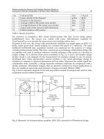
Fig. 1. Power spectrum of the transmitted signal
In order to avoid a large number of modulators and filters at the transmitter and
complementary filters and demodulators at the receiver, it is desirable to be able to use
modern digital signal processing techniques, such as fast Fourier transform (FFT).
OFDM is a promising candidate for achieving high data rates in mobile environment
because of its multicarrier modulation technique and ability to convert a frequency selective
fading channel into several nearly flat fading channels.
This technology has been chosen as the transmission method of many standards, such as
Digital Subscribe Line (DSL), European Digital Audio and Video Broadcasting terrestrial
(DAB/DVB-T), European HIPERLAN/2 and IEEE 802.11 a/g for wireless local area
networks (WLAN), Worldwide Interoperability for Microwave Access (WiMAX), etc.
However, OFDM systems exhibit a sensitivity to phase noise higher than single carrier
modulations due to its long symbol period. Because carriers are kept very close to each
other, OFDM is very sensitive to distortion that may remove the orthogonality between
carriers. The crystal oscillator used in a mixer generates phase noise. It can also be caused by
Recent Advances in Wireless Communications and Networks
42
AWGN present at the input of a Phase Locked Loop (PLL) in a coherent receiver. Phase
noise can cause several types of signal degradation that are usually very difficult to quantify
analytically. When the modulation experiences phase noise, it encounters two problems: 1) a
common phase rotation over all the carrier frequencies which rotate the entire signal space
for a given OFDM symbol and 2) inter-carrier interference due to the loss of orthogonality
between subcarriers. Especially, the ICI seriously degrades system predominance because it
may break down the orthogonality between subcarriers.
There have been many previous works on the phase noise, frequency offset and reduction of
ICI. Among them the following methods are discussed and compared in this chapter. In the
next section the OFDM system is introduced and its benefits along with its drawbacks are
analyzed. ICI reduction methods such as pulse shaping and self-cancellation are given in
section 3 and the last section concludes the chapter.
2. OFDM system
Figure 2 shows the block diagram of a typical OFDM system. The transmitter section
converts digital data to be transmitted, into a mapping of subcarrier amplitude and phase. It
then transforms this spectral representation of the data into the time domain using an
Inverse Discrete Fourier Transform (IDFT). The Inverse Fast Fourier Transform (IFFT)
performs the 20 same operations as an IDFT, except that it is much more computationally
efficient, and so is used in all practical systems. In order to transmit the OFDM signal the
calculated time domain signal is then mixed up to the required frequency. The receiver
performs the reverse operation of the transmitter, mixing the RF signal to base band for
processing, then using a Fast Fourier Transform (FFT) to analyze the signal in the frequency
domain. The amplitude and phase of the subcarriers is then picked out and converted back
to digital data. The IFFT and the FFT are complementary function and the most appropriate
term depends on whether the signal is being received or generated. In cases where the
signal is independent of this distinction then the term FFT and IFFT is used interchangeably.
The high data rate serial input bit stream is fed into serial to parallel converter to get low
data rate output parallel bit stream. Input bit stream is taken as binary data. The low data
rate parallel bit stream is modulated in Signal Mapper. Modulation can be BPSK, QPSK,
QAM, etc. The modulated data are served as input to inverse fast Fourier transform so that
each subcarrier is assigned with a specific frequency. The frequencies selected are
orthogonal frequencies. In this block, orthogonality in subcarriers is introduced. In IFFT, the
frequency domain OFDM symbols are converted into time domain OFDM symbols. Guard
interval is introduced in each OFDM symbol to eliminate inter symbol interference (ISI). All
the OFDM symbols are taken as input to parallel to serial data. These OFDM symbols
constitute a frame. A number of frames can be regarded as one OFDM signal. This OFDM
signal is allowed to pass through digital to analog converter (DAC). In DAC the OFDM
signal is fed to RF power amplifier for transmission. Then the signal is allowed to pass
through additive white Gaussian noise channel (AWGN channel). At the receiver part, the
received OFDM signal is fed to analog to digital converter (ADC) and is taken as input to
serial to parallel converter. In these parallel OFDM symbols, Guard interval is removed and
it is allowed to pass through Fast Fourier transform. Here the time domain OFDM symbols
are converted into frequency domain. After this, it is fed into Signal Demapper for
demodulation purpose. And finally the low data rate parallel bit stream is converted into
high data rate serial bit stream which is in form of binary.
ICI Reduction Methods in OFDM Systems
43
Fig. 2. OFDM system implementation
By the insertion of an extra guard interval between successive OFDM symbols the Inter
Symbol Interference (ISI) can be avoided. The guard interval could be a section of all zero
samples transmitted in front of each OFDM symbol and its duration should be more than
the channel delay spread (L
c
). It should be considered that in practical systems the guard
interval is not used. Instead, Cyclic Prefix (CP) is inserted to combat the multipath-channel
by making the channel estimation simple. The cyclic prefix is a replica of the last L
p
samples
of the OFDM symbol where L
p
> L
c
. Because of the way in which the cyclic prefix was
formed, the cyclically-extended OFDM symbol now appears periodic when convolved with
the channel. An important result is that the effect of the channel becomes multiplicative.
For the better understanding of this issue assume that the impulse response of the channel is
,
,…,
and the i-th transmitted signal block in the output of IFFT block is
,
,
,
,…,
,
. In this condition the cyclic prefix would be
,
,
,
,…,
,
. The
symbols of the received baseband signal after the transmission through the channel are
equal to:
,
,
,
,
,
,
,
,
,
,
,
,
,
,
,
,
,
,
,
,
(1)
At the receiver the first L
c
+1 symbols are discarded and the N remained symbols are
demodulated using an N-point FFT. So the data on the k-th subcarrier is as follows: