Coherence and Ultrashort Pulse Laser Emission Part 6 docx
Bạn đang xem bản rút gọn của tài liệu. Xem và tải ngay bản đầy đủ của tài liệu tại đây (705.26 KB, 40 trang )
Coherence and Ultrashort Pulse Laser Emission
192
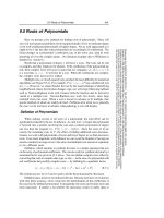
Fig. 1. The energy conversion efficiency vs KDP thickness, fundamental intensity 5TW/cm
2
As can be seen from fig.1 optimal KDP crystal for effective SHG of 910nm, 50fs and
I=5TW/cm
2
fundamental radiation is about 0.4mm, but the one for 800nm and the same
parameters is about 0.3mm. The shorter pulses at the intensity level require thinner crystals.
For instance, 20fs and 910nm the crystal length should be about 0.35mm, but for 800nm it is
about 0.25mm. The right choice of nonlinear element thickness gives opportunity to obtain
more than 50% efficiency of energy conversion even for 20fs, 5TW/cm
2
fundamental
radiation in KDP crystal.
The length of group velocity mismatch can be varied by means of changing parameters of
frequency doubling element. Deuteration factor – D in DKDP crystals can be chosen during
their growth stage. Refractive index of the crystal depends on the deuteration factor, and
hence group velocities of fundamental and second harmonic pulses can be varied. In fig.2
we present dependence dispersion parameter P(λ) from fundamental wave length at
different level of deuteration factor in DKDP crystal. We used DKDP properties from the
work(Lozhkarev, Freidman et al. 2005).
According to fig.2, dispersion parameter P(λ) (calculated for DKDP crystal) is equal to zero
only for one fundamental wave length. In this case group velocities of fundamental and
second harmonic pulses are equal. Evidently, the situation is optimal for frequency doubling
process. For the deuteration factor D=0 (KDP crystal) optimal central wave length of
fundamental pulse is 1033nm. The increasing of deuteration factor leads to optimal wave
length varying. The D range 0 – 1 corresponds to diapason of optimal wave lengths 1033–
1210 nm. So, the level variation of the deuteration can be used for managing of dispersion
properties of frequency doubling nonlinear element. The dependence of refractive index for
KDP and DKDP crystals from temperature can not be used for managing of dispersion
properties. At the present, the crystals are optimal for SHG of super powerful ultra short
laser pulses. As far as, created from the crystals nonlinear elements can be done with large
Second Harmonic Generation under Strong Influence of Dispersion and Cubic Nonlinearity Effects
193
aperture (about 10 cm) and half millimeter thickness or less. The properties are crucial for
the application.
0.7 0.8 0.9 1 1.1 1.2 1.3 1.4 1.5
0
50
100
150
Fundamental wave length,
μ
fs/mm
D=0
D=0.5
D=1
Fig. 2. Dispersion parameter P(λ) versus fundamental wave length at deuteration level
D=0,0.5 and 1.
In order to verify theoretical model of SHG process under strong influence of cubic
polarization effects we implemented modeling experiments. In the experiments we used
output radiation of front end system of petawatt level femtosecond OPCPA laser (Lozhkarev,
Freidman et al. 2007) as a fundamental beam. The parameters of the radiation incident on the
SHG crystal (0.6 or 1.0mm thickness) were the following: beam diameter 4.3mm, pulse
duration 65fs, energy range 1÷18 mJ, and central wavelength 910 nm. It is necessary to point
out that the beam quality was not good, as a result at 18mJ energy the average over cross-
section intensity was 2TW/cm
2
and the peak intensity was 5TW/cm
2
. All measurements were
done in vacuum, because for the range of fundamental intensities nonlinear beam self-action in
air is important, even at several centimeters of propagation distance.
We have measured the energy efficiency of SHG in 0.6mm-thick KDP crystal at different
detuning external angles Δθ, see fig.3. The main goal was to experimentally verify the fact that
for efficient SHG different intensities require different optimal angles of beam propagation.
As can be seen from fig.3, a perfect phase matching (i.e. Δθ=0mrad) is optimal for SHG
efficiency at low (2÷4mJ) and medium (10mJ) input energies. But at high energies (18mJ)
SHG is more efficient at the optimal detuning angle Δθ=- 3.1mrad, because the phase
induced by third-order nonlinearity and linear phase mismatching compensate each other.
A negative value of optimal detuning angle is also clearly seen from comparison of data for
Δθ=-6.2mrad and Δθ=6.2mrad: SHG efficiency is almost the same at 2-4mJ and is noticeably
different at 16-18mJ. The experimental results are in a good agreement with formula (2),
which gives for 18mJ energy (average intensity 2TW/cm
2
) Δθ=-3.5mrad.
Relatively low SHG efficiency and large spread of the experimental data are explained by
poor quality of both the beam and the ultra thin KDP crystal. In a 1mm-thick KDP crystal
we reached 41% of SHG energy efficiency at such high intensities.
Coherence and Ultrashort Pulse Laser Emission
194
0
0.1
0.2
0.3
0 5 10 15 20
fundamental pulse energy, mJ
SHG efficiency
0 0.5 1 1.5 2
average intensity, TW/cm
2
0 mrad (phase matching)
-3.1 mrad
3.1 mrad
-6.2 mrad
6.2 mrad
Fig. 3. The energy conversion efficiency versus input fundamental pulse energy at different
detuning (external angles) from linear phase matching direction.
3. Pulse shortening and ICR enhancement
Cubic polarization leads to fundamental and second harmonic pulses spectrum
modification and widening. The phenomenon depends on fundamental pulse intensity,
cubic nonlinearity, fundamental central wave length and nonlinear element thickness. The
output second harmonic pulse is not Fourier transform limited. In the case of optimal
nonlinear element thickness, duration of second harmonic radiation approximately equals to
the one of input pulse. Additional correction of spectrum phase of output second harmonic
pulse makes it possible to significantly reduce pulse duration. The simplest way is the
second order phase correction:
2
1
22
() ( ,) ,
iS
comp
AtFeFAzLt
ω
−
⎡
⎤
==
⎡
⎤
⎣
⎦
⎢
⎥
⎣
⎦
here F, F
-1
are the direct and inverse Fourier transforms, А
2
(z=L,t), A
2comp
(t) are the electric
fields of second harmonic radiation before and after phase correction, and S is the coefficient
of quadratic spectral phase correction. The electric field А
2
(z=L,t) is obtained by the
numerical solution of (1). The results are presented in fig.4 for optimal detuning angle Δθ (2)
and for 5TW/cm
2
fundamental Gaussian pulse (20fs FWHM). The coefficient S was chosen
to minimize the pulse duration. Maximums of all the three pulses were shifted to zero time
for clarity.
In accordance with fig.4, SHG process increases temporal ICR on pulse wings. Additional
spectrum phase correction allows significantly reduce pulse duration. For instances, for
fundamental wavelength Gaussian pulse with duration 20fs (FWHM) and intensity
5TW/cm
2
, the second harmonic pulse may be compressed to 12fs (800nm, 0.2mm-thick
Second Harmonic Generation under Strong Influence of Dispersion and Cubic Nonlinearity Effects
195
Fig. 4. Shapes of incident and second harmonic pulses before and after spectral phase
correction. (a) fundamental wavelength 910 nm, KDP thickness 0.4 mm; (b) fundamental
wavelength 800 nm, KDP thickness 0.2 mm.
KDP) and to 9fs (910nm, 0.4mm-thick KDP). The 50fs input pulse may be compressed even
more efficiently in a 0.4mm-thick KDP: to 18fs at 800nm and to 16fs at 910nm.
The spectrum phase correction decreases ICR of second harmonic pulse in comparison with
uncompressed, but it is higher than fundamental. As a result, SHG together with additional
spectrum phase correction is suitable for peak intensity increasing and improvement of
temporal intensity profile of super strong laser radiation.
4. Plane wave instability in mediums with quadratic and cubic nonlinearities
The other negative manifestation of cubic polarization is small-scale self-focusing (SSSF).
The process is the main cause of laser beam filamentation and nonlinear element
destructions. The theoretical aspects of the phenomenon in media with cubic polarization
are observed in literature (Bespalov and Talanov 1966; Rozanov and Smirnov 1980;
Lowdermilk and Milam 1981; Poteomkin, Martyanov et al. 2009). The main goal of the
section is to develop theoretical approach to describe the process in media with quadratic
and cubic nonlinearity. The model (Ginzburg, Lozhkarev et al. 2010) is necessary for
estimations of critical level of spatial noise in super strong laser beams.
Let’s assign three fundamental plane waves on the input surface of frequency doubling
nonlinear element (waves 1, 3, 4 see fig 4). Angles α
1
and α
2
determine directions of
harmonic disturbances of laser beam in non critical and critical planes of frequency doubling
nonlinear element. Let’s consider, that waves 3 and 4 has equal by amount, but anti
directional transverse wave vectors. The wave 1 is significantly more powerful, than waves
3 and 4, and it runs in the optimal direction for energy conversion (in accordance with
formula 2). Second harmonic wave (wave 2), which is generated by the wave number 1, runs
at the same direction too.
Weak fundamental waves (3, 4) interact with strong waves (1, 2) and generate harmonic
disturbances of second harmonic radiation (waves 5 and 6) see fig 4. The transversal wave
vectors of fundamental and second harmonic waves should be equal. The requirement is a
Coherence and Ultrashort Pulse Laser Emission
196
Fig. 4. The scheme of runs strong fundamental (wave 1) and second harmonic (wave 2)
waves and their harmonic disturbances (waves 3,4 and 5,6 correspondingly) in non critical
(a) and critical plane of frequency doubling nonlinear element.
consequence of Maxwell equations. The directions of second harmonic beam disturbances in
non critical (
11 21
,
φ
φ
) and critical (
12 22
,
φ
φ
) planes are determined by boundary conditions
(3):
12512 12622
1 2 1 5 12 11 1 2 1 6 22 21
sin( ) sin( ) sin( ) sin( )
cos( )sin( ) cos( )sin( ) cos( )sin( ) cos( )sin( )
kk kk
kk kk
αφ αφ
α
αφφ ααφφ
==
==
(3)
So, the beam disturbances 3, 4, 5 and 6 have equal transversal wave vectors and their
amplitudes satisfy the demands:
12
,(3 6)
i
i
εεε
<< = (4)
Assume, that on the boundary of the frequency doubling nonlinear element (z=0) the
amplitudes of strong waves are the following:
ε
1
(z=0)=ε
10
and ε
2
(z=0)=0 (5)
Here ε
10
–
the electric field of the fundamental string wave (1). The conditions for harmonic
disturbance amplitudes:
34305,6
( 0) ( 0) , ( 0) 0,
i
zz ez
ϕ
εεεε
=
===⋅ == (6)
here ε
30
and φ the initial electric strength of waves 3,4 and their phase on the entrance
surface of nonlinear element. Assume, that amplification of harmonic disturbances is not
crucial for strong wave interaction, i.e. amplitudes of wave 1 and 2 satisfy the system of
differential equations:
a)
b)
3
5
1,2
6
4
z
1
α
1
α
11
φ
21
φ
О.О.
x
2
α
2
α
22
φ
12
φ
3
5
1,2
6
4
z
y
Second Harmonic Generation under Strong Influence of Dispersion and Cubic Nonlinearity Effects
197
22
1
2 1 11 1 1 12 2 1
22
2
2
121122222
,
,
ikz
ikz
d
iei i
dz
d
iei i
dz
ε
β
εε γ ε ε γ ε ε
ε
βε γ ε ε γ ε ε
∗−Δ⋅
Δ⋅
=
−⋅⋅⋅⋅ −⋅ ⋅ ⋅−⋅ ⋅ ⋅
=− ⋅ ⋅ ⋅ − ⋅ ⋅ ⋅ − ⋅ ⋅ ⋅
(7)
Now, observe mathematical description of plane wave instability in media with quadratic
and cubic nonlinearity. Implementation of standard linearization procedure to quasi-optical
equations, which describe dynamic of each frequency component, and grouping items with
equal transverse wave vectors, gives opportunity to obtain equations for amplitudes of
harmonic disturbances:
11 2
22
cos( )cos( )
** 2* * *
3
1 5 4 2 11 1 4 1 3 12 2 3 1 2 6 1 5 2
12
22
** 2* *
4
1 6 3 2 11 1 3 1 4 12 2 4 1 2 5 1 6
12
2
cos( )cos( )
2
cos( )cos( )
ik z
d
i
EE EE EE E E E E EEE EEE e
dz
di
EE EE EE E E E E EEE EE
dz
αα
ε
βγ γ
αα
ε
βγ γ
αα
−
⎡⎤
⎡⎤⎡ ⎤
⎡⎤
=++++++
⎢⎥
⎢⎥⎢ ⎥
⎣⎦
⎣⎦⎣ ⎦
⎣⎦
−
⎡⎤
⎡⎤
=++++++
⎢⎥
⎣⎦
⎣⎦
11 2
511 12
cos( )cos( )
*
2
222
cos( )cos( )
** *
5
31 21 1 5 124 123 22 2 6 2 5
11 12
2
**
6
41 21 1 6 123 124
21 22
22
cos( )cos( )
2
cos( )cos( )
ik z
ik z
Ee
d
i
EE E E EEE EEE E E E E e
dz
d
i
EE E E EEE EEE
dz
αα
φφ
ε
βγ γ
φφ
ε
βγ
φφ
⎡⎤
⎡⎤
⎢⎥
⎢⎥
⎣⎦
⎣⎦
−
⎡⎤
⎡⎤⎡⎤
=+++++
⎢⎥
⎢⎥⎢⎥
⎣⎦⎣⎦
⎣⎦
−
=+++
621 22
22
cos( )cos( )
*
22 2 5 2 6
2
ik z
EE EE e
φφ
γ
⎡⎤
⎡⎤⎡⎤
++
⎢⎥
⎢⎥⎢⎥
⎣⎦⎣⎦
⎣⎦
(8)
Here
zi
ik z
ii
Ee
ε
−
= , k
1
– magnitude of fundamental wave vector, k
5
, k
6
– wave vectors of
second harmonic wave disturbances. In the frame of the model, the disturbances in the
second harmonic beam appear from interaction between fundamental disturbances and
strong fundamental wave (1). The second harmonic beam modulation is amplified over
cubic polarization.
The amplification of harmonic disturbances depends on entrance fundamental intensity,
quadratic and cubic nonlinearity, linear wave vectors mismatch, initial phase φ on the
entrance surface of frequency doubling media. The gain factors of fundamental and second
harmonic disturbances can be determined (i=3 6):
εααϕ
ααϕ
ε
=
2
12
12
2
30
(, , , )
(, , , )
i
i
z
Gz
.
As a rule, initial phase φ is a random parameter, and hence the averaged gain factors are
mostly interested in theoretical investigations:
2
12 12
0
1
(, , ) (, , , )
2
avi i
Gz Gz d
π
α
αααϕϕ
π
=
∫
.
The averaged gain factors G
av1,2
versus harmonic disturbances propagation directions (α
1
,
α
2
) are presented in fig.4 for 0.5mm KDP crystal, 4.5 ТW/cm
2
fundamental intensity and
assumption of optimal direction of beam propagation (in accordance with formula 2).
In accordance with fig 5, maximum of averaged by initial phase gain factors of fundamental
and second harmonic disturbances, which were calculated for I=4.5 TW/cm
2
and 0.5mm
KDP thickness, are the following G
av1
=14, G
av2
=270. Angular detuning in critical plane
imposes restrictions on amplification of harmonic disturbances. As a result of it, angular
Coherence and Ultrashort Pulse Laser Emission
198
Fig. 5. The averaged gain factors of harmonic disturbances versus angles (α
1
, α
2
) a) G
av
fundamental and b) G
av
second harmonic. The diagrams were obtained by numerical
solution of systems differential equations (7) and (8) with boundary conditions 5 and 6, KDP
thicknesses 0.5mm and fundamental intensity I=4.5 TW/cm
2
.
diagram in fig. 5 are symmetrical in non critical plane, i.e. G
avi
(z,-α
1
,α
2
)=G
avi
(z,α
1
,α
2
) and
non symmetrical in critical plane G
avi
(z,α
1
,-α
2
)≠G
avi
(z,α
1
,α
2
). Maximum amplification of
harmonic disturbances of second harmonic wave (2) takes place at angles α
1
=42 mrad and
α
2
=0 from direction of strong waves (1 and 2) propagation.
Note that for media with only cubic nonlinearity the gain factor can be found analytically
(Rozanov and Smirnov 1980):
2
2
2
222
11 1 11
11 11 11
2
11
111
12 4
2cosh ( ) sinh ( ) sinh ( ) ,
42
4
th
Bx B
GBxBxBx
Bx
B
κ
κ
⎛⎞
⎛⎞
⎛⎞
−
⎜⎟
=+ +
⎜⎟⎜⎟
⎜⎟
⎜⎟
⎜⎟
−
⎜⎟
⎝⎠ ⎝⎠
⎝⎠
here B
11
=γ
11
A
10
2
L is B-integral,
24
2
11
2
11
11
4
x
B
B
κκ
=− ,
11 1
kLk
κ
⊥
= - normalized transversal
wave vector.
The other important parameter, which characterizes SSSF, is integral by spatial spectrum
gain factor of harmonic disturbances. Let’s determine it for the task by the following way:
int 1 2
2
1
jj
av
jj
cr
GGdd
α
α
πα
Ω
=
∫∫
here j=1,2 indexes of gain factors of noise amplification of fundamental and second
harmonic wave, α
cr
– angle in non critical plane, which corresponds to decreasing the gain
factor of second harmonic disturbances in e times from the maximum value; Ω – is the circle
of radius α
cr
. Despite the complicated determination of the integral gain factors, they are
physically enough, because it takes into account anisotropic topology of the gain structure
(see fig.5). Calculated by the way integral gain factors for fundamental radiation
I=4.5 TW/cm
2
and 0.5 mm KDP thickness are equal to G
int1
=5, G
int2
=107. Integral gain
factors versus B-integral are presented in fig 6.
-50 0 50
-50
0
50
-50 0 50
-50
0
50
2
4
6
8
10
12
50
100
150
200
250
Angle in non critical plane, α
1
mrad Angle in non critical plane, α
1
mrad
Angle in critical plane, α
2
mrad
Angle in critical plane, α
2
mrad
a) b)
Second Harmonic Generation under Strong Influence of Dispersion and Cubic Nonlinearity Effects
199
1 1.5 2 2.5 3 3.5 4
10
-1
10
0
10
1
10
2
10
3
10
4
B
11
G
int 1
G
int 2
G
int
,
β
=0
Fig. 6. Integral gain factors G
int1,2
fundamental and second harmonic disturbances versus B-
integral
As can be seen from fig 6, the harmonic disturbances of fundamental and second harmonic
waves are amplified significantly during second harmonic generation process. The fact can
be a cause of a nonlinear element corruption.
Let’s found critical level of spatial noise in the fundamental beam on the entrance surface of
nonlinear element. Peak amount and mean square deviation intensity I
rms
from average in
beam profile are connected with relative noise power P
n
/P by the following empiric
formulas (Rozanov and Smirnov 1980):
()
()
2
peak av n
2
rms av n
I/I 15P/P
I/I 1P/P 1
=+
=
+−
(9)
In accordance with (Kumar, Harsha et al. 2007), KDP crystal can stand under intensity about
I
peak
=18.5 ТW/cm
2
, 100fs pulse duration and central wave length λ=795 nm. Let’s assume that
the peak intensity is the threshold level for crystal destruction. In this case
th peak av
KI/I4.1== for average intensity I
av
=4.5 TW/cm
2
. Noise power on the output
surface of frequency doubling nonlinear element can be found like
nout
PGP
n
=
⋅ . Critical level
of noise power
nn
KP/P
=
of the fundamental entrance beam (by means of 9) is the following:
()
2
nth
11
KK1
G5
⎛⎞
=−
⎜⎟
⎝⎠
.
For gain factor G=107 the amount is K
n
=4·10
-4
and
2
rms av
I/I 410
−
=⋅ . The influence of SSSF
effects can be diminished by means of beam quality improving and self filtering
implementation, see next section.
Coherence and Ultrashort Pulse Laser Emission
200
5. Small-scale self-focusing suppression
The presented estimations of noise power critical level are overstated. The question is that,
the observed theoretical model assumes the presence of high amplifying harmonic
disturbances in nonlinear element and in the area of strong field. According to the observed
theoretical model directions, where noise components start to be more intensive, depends
on many factors such as fundamental intensity and central wave length, quadratic and cubic
nonlinearity, direction of strong wave propagation with respect to optical axe, and thickness
of frequency doubling nonlinear element. For fundamental intensity 4.5TW/cm
2
and 0.5mm
KDP crystal the optimal angle for amplification of harmonic disturbance is 42 mrad (fig. 5).
Such high angles make it possible to use free space propagation to cut off dangerous spatial
components from strong light beam and there is no necessity to use spatial filters. The main
sources of harmonic disturbances are mirror surfaces. Hence, the distance between the last
mirror and nonlinear element is important parameter for spatial spectrum clipping (see
fig 7).
Fig. 7. The idea of small-scale self-focusing suppression. d is beam diameter, D is free-space
propagation distance, α is angle of propagation of noise wave.
Differential equations 7 and 8 make it possible to find angle of optimal spatial noise
increasing – α
max
. The safety distance is
22
max
max
1sin()
2sin( )
dn
D
n
α
α
⋅−⋅
≥
⋅⋅
, there
d is the entrance
beam diameter,
n – refractive index. This idea of small-scale self-focusing suppression by
beam self-filtering due to free propagation before SHG may be used in any high intensity
laser. The key parameters of the task are B-integral and angle of view
d/D.
The power of noise on the entrance surface can be calculated by the following expression:
2
12oo o
PPdd P
α
α
αα πα
Ω
==
∫∫
here
P
αo
– angular power density, α
1
и α
2
angles in non critical and critical plane, Ω – area in
angular parameter space. On the entrance surface angular power density is homogeneous
and the
Ω is the circle with radius α and center in the origin of coordinates. On the output
surface the noise power is the following:
()
2
12 12 int
,
out o o
PPG ddP G
αα
αα αα πα
Ω
==⋅⋅⋅
∫∫
Second Harmonic Generation under Strong Influence of Dispersion and Cubic Nonlinearity Effects
201
Output noise power is proportional to α
2
·G
int
. Maximum angle of integration is determined
by the optical scheme geometry and refraction angle of frequency doubling nonlinear
element.
Fig. 8. Logarithm of normalized power of noise
ln(F) versus B-integral and angle of view
d/D at intensity 5TW/cm
2
. Open circles show experiments without filamentaion and fill
circles show experiment with filamentation.
The dependence of normalized power of the spatial noise
F=P
out
(B,d/D)/ P
out
(B=2.5, d/D=1) at
the output of nonlinear element is presented in fig. 8. At a large angle of view
d/D (no self-
filtering) all noise waves reach the nonlinear element and noise power at its output is the
highest. In this case filamentation appears at B≈2.5 (F≈1), the fact was observed in our
experiments in accordance with other papers (Bespalov and Talanov 1966; Bunkenberg,
Boles et al. 1981; Speck 1981; Vlasov, Kryzhanovskiĭ et al. 1982). When
d/D reduces to about
0.2 the noise power decreases as well. It drops sharply when
d/D<0.1. As on can see from
fig.3, experimental points with 0.6mm and 1mm thick crystal (
d/D=0.02) are in a safety
region:
F<<1 even though B=3.8 and 6.4 correspondingly. On the other hand for
experimental points where filamentaion was observed (
d/D=0.08) the F parameter is above
unity, see fig.8.
Note, that in nanosecond lasers the typical intensity is 1GW/cm
2
, hence, self-filtering takes
place at the angle of view
d/D<0.003, because the angle is proportional to the square root of
laser beam intensity. Such a small value limits practical use of self-filtering for 1GW/cm
2
intensity laser pulses. The critical angle for medium with cubic nonlinearity only can be
found in accordance with the following formula:
2
cr
I
n
γ
α
=
Here γ- cubic nonlinearity coefficient [cm
2
·watt
-1
], I – intensity [cm-
2
·watt] and n - refractive
index.
Coherence and Ultrashort Pulse Laser Emission
202
6. Surface dust influence to SHG process
Surface dusts are conductive to harmonic disturbance generation. The observed small-scale
self-focusing suppression scheme can not be used for clipping spatial spectrum of noises,
which are generated on surface. Generated on nonlinear element surface harmonic
components have the same initial phase, which is equal to zero. The dynamic of plane wave
instability can be described by system of differential equations 7 and 8. In this case
boundary conditions are the following:
(
)
110
0z
ε
ε
== ,
(
)
2
00,z
ε
=
=
(
)
3,4 10
0z
ε
ε
== ,
(
)
5,6
00z
ε
=
=
Gain factors versus of angles of harmonic disturbance propagation are presented in fig.9.
Fig. 9. Gain factors of harmonic disturbances a) fundamental and b) second harmonic
waves. Calculated for 0.5mm KDP crystal and intensity 4.5TW/cm
2
, angle of strong wave’s
propagation is optimal according to (2).
In accordance with fig.9 gain factors of harmonic disturbances of fundamental and second
harmonic waves, which appears from scattering strong waves on surface dusts have
topological structure the same to the averaged by initial phase gain factors. In this case
preferable direction for noise amplification lies in non critical plane too. For fundamental
intensity 4.5TW/cm
2
and 0.5mm KDP crystal the maximum gain factor of fundamental
disturbances is 20, as for second harmonic noise it is 216 by optimal angle ±35mrad in non
critical plane.
Thus, gain factors of harmonic disturbances of second harmonic wave, which is generated
on surface dusts, are big sufficiently. In case of use of self-filtering technique described in
Section 5, the input surface of SHG crystal is the main source of the noises. It is needed to be
taken into consideration during experimental investigations.
Angle in critical plane, α
2
rad
Angle in critical plane, α
rad
Angle in critical plane, α
1
rad Angle in critical plane, α
1
rad
Second Harmonic Generation under Strong Influence of Dispersion and Cubic Nonlinearity Effects
203
7. Conclusion
We presented experimental conformation of theoretical model of SHG of super strong
femtosecond radiation under strong influence of dispersion and cubic polarization effects.
Despite the poor quality of the fundamental beam, the energy conversion efficiency of 35%
(41%) was achieved in 0.6 (1.0) mm-thick KDP crystal.
SHG process is well for a increasing of temporal intensity contrast ratio significantly. The
suggested additional spectrum phase correction of output second harmonic radiation is a
way to reduce pulse duration more than 3 times for 50fs, 5TW/cm
2
and 0.4mm KDP crystal.
We demonstrated significant difference between 910nm and 800nm fundamental waves for
SHG process and established the privilege of the first one.
The developed theoretical model of plane wave instability in mediums with quadratic and
cubic nonlinearity makes it possible to estimate critical level of spatial noises power in super
strong femtosecond laser beams for safety realization of SHG process. The suggested
scheme of small-scale self-focusing suppression is theoretically explained and
experimentally verified: no manifestation of self-focusing at B-integral above 6. The
obtained experimental results are in a good agreement with the model. In the conclusion it
is necessary to point out two additional sources of spatial noises as apply to SHG process.
The first one is surface inhomogeneous and the second one is internal refractive index
disturbances. The methodic of minimization of the factors is the improvement of nonlinear
element quality: surface and homogeneity of refractive index.
8. References
Akhmanov, S. A., V. A. Vysloukh, et al. (1988). Optika femtosekundnykh lazernykh
impul'sov. Moscow, Nauka.
Aoyama, M., K. Yamakawa, et al. (2003). "0.85-PW, 33-fs Ti:sapphire laser." Optics Letters
28(17): 1594-1596.
Bespalov, V. I. and V. I. Talanov (1966). "Filamentary structure of light beams in nonlinear
liquids." JETP Letters 3: 307-310.
Bunkenberg, J., J. Boles, et al. (1981). "The omega high-power phosphate-glass system:
design and performance." IEEE Journal of Quantum Electronics QE-17(9): 1620-
1628.
Chien, C. Y., G. Korn, et al. (1995). "Highly efficient second-harmonic generation of
ultraintense Nd:glass laser pulses." Optics Letters 20(4): 353–355.
Choe, W., P. P. Banerjee, et al. (1991). "Second-harmonic generation in an optical medium
with second- and third-order nonlinear susceptibilities." J. Opt. Soc. Am. B 8(5):
1013–1022.
Ditmire, T., A. M. Rubenchik, et al. (1996). "The effect of the cubic onlinearity on the
frequency doubling of high power laser pulses." J. Opt. Soc. Am. B 13(14): 649–655.
Ginzburg, V. N., V. V. Lozhkarev, et al. (2010). "Influence of small-scale self-focusing on
second harmonic generation in an intense laser field." Quantum Electronics 40(6):
503-508.
Kochetkova, M. S., M. A. Martyanov, et al. (2009). "Experimental observation of the small-
scale self-focusing of a beam in the nondestructive regime." Quantum Electronics
39(10): 923-927.
Coherence and Ultrashort Pulse Laser Emission
204
Kumar, R. S., S. S. Harsha, et al. (2007). "Broadband supercontinuum generation in a single
potassium di-hydrogen phosphate (KDP) crystal achieved in tandem with sum
frequency generation." Appl. Phys. B 86: 615-621.
Liang, X., Y. Leng, et al. (2007 ). "Parasitic lasing suppression in high gain femtosecond
petawatt Ti:sapphire amplifier." Optics Express 15(23): 15335-15341.
Lowdermilk, W. H. and D. Milam (1981). "Laser-induced surface and coating damage." IEEE
Journal of Quantum Electronics QE-17(9): 1888-1902.
Lozhkarev, V. V., G. I. Freidman, et al. (2007). "Compact 0.56 petawatt laser system based on
optical parametric chirped pulse amplification in KD*P crystals." Laser Physics
Letters 4(6): 421-427.
Lozhkarev, V. V., G. I. Freidman, et al. (2005). "Study of broadband optical parametric
chirped pulse amplification in DKDP crystal pumped by the second harmonic of a
Nd:YLF laser." Laser Physics 15(9): 1319-1333.
Mironov, S. Y., V. V. Lozhkarev, et al. (2009). "High-efficiency second-harmonic generation
of superintense ultrashort laser pulses." Applied Optics 48(11): 2051-2057.
Poteomkin, A. K., M. A. Martyanov, et al. (2009). "Compact 300 J/ 300 GW frequency
doubled neodimium glass laser. Part I: Limiting power by self-focusing." IEEE
Journal of Quantum Electronics 45(4): 336-344.
Razumikhina, T. B., L. S. Telegin, et al. (1984). "Three-frequency interactions of high-
intensity light waves in media with quadratic and cubic nonlinearities." Sov. J.
Quantum Electron 14.
Rozanov, N. N. and V. A. Smirnov (1980). "Small-scale self-focusing of laser radiation in
amplifier systems." Soviet Journal of Quantum Electronics 10(2): 232-237.
Speck, D. R. (1981). "The shiva laser-fusion facility." IEEE Journal of Quantum Electronics
QE-17(9): 1599-1619.
Vlasov, S. N., V. I. Kryzhanovskiĭ, et al. (1982). "Use of circularly polarized optical beams to
suppress selffocusing instability in a nonlinear cubic medium with repeaters "
Soviet Journal of Quantum Electronics 12(1): 7-10.
Yanovsky, V., V. Chvykov, et al. (2008 ). "Ultra-high intensity- 300-TW laser at 0.1 Hz
repetition rate." Optics Express 16(3): 2109-2114.
10
Temporal Stretching of Short Pulses
Rajeev Khare and Paritosh K. Shukla
Raja Ramanna Centre for Advanced Technology
Department of Atomic Energy
India
1. Introduction
Many lasers operate predominantly or only as pulsed sources and the pulse duration is
determined by the duration of effective pumping, intra-resonator energy extraction rates,
etc. However, in certain applications of the pulsed lasers, it is necessary to extend the
duration of the laser pulses without reducing its pulse energy. The duration of laser pulses
is increased by using laser pulse stretchers, which stretch the pulses temporally. An ideal
laser pulse stretcher increases the duration of the laser pulse without introducing losses so
the peak power of the laser is reduced without reducing its average power. The temporal
stretching of laser pulses is vital for many applications of pulsed lasers. The temporal
stretching of oscillator pulses of high beam quality is required in oscillator–amplifier
systems for achieving high output power. The temporal stretching of pump laser pulses
leads to an increase in energy conversion efficiency and tuning range along with a decrease
in linewidth of the tunable dye lasers. While launching the laser pulses of high energy into
optical fibers, the temporal stretching of laser pulses is done to reduce the peak power,
without reducing the pulse energy, to save the input faces of optical fibers from damage.
Thus the temporal stretching of laser pulses also increases the upper limit of transmission of
pulse energy in the optical fibers. The optical pulse stretchers are used for removing laser-
induced plasma spark generation in spontaneous Raman-scattering spectroscopy by
reducing the peak power. In the guide star experiments, the pulse stretching of laser pulses
is required to avoid saturation effects. The temporal pulse stretching is required in material
processing because a stretched pulse is more efficient for heating the material. The temporal
stretching of laser pulses is needed in optical microlithography to avoid degradation of
semiconductor materials as well as optics. In the medical application of lasers, the pulse
stretching of laser pulses is done to reduce the high peak intensities, which generally
damage the tissues. The temporal stretching of laser pulses is done in holographic
interferometry for removing the boiling effect, which is detrimental to the quality of the
photographs. The ultrashort pulses are temporally stretched in the chirped pulse
amplification (CPA) to avoid the nonlinear effects that lead to catastrophic damage. There
are many more important applications, where temporal stretching of laser pulses is done.
Various types of laser pulse stretchers, both passive and active, are developed according to
the type of the laser and the requirements of the application.
Coherence and Ultrashort Pulse Laser Emission
206
2. Techniques of temporal stretching of laser pulses
Based on the physics and technology, the techniques of temporal stretching of laser pulses
can be broadly classified into four categories; (a) optical pulse stretching, (b) pulse stretching
by intracavity nonlinear materials (c) electronic pulse stretching and (d) pulse stretching by
dispersion.
2.1 Optical pulse stretching
The technique of optical pulse stretching uses a configuration of optical elements that split
the amplitude of the incident laser pulse and introduce optical delays among them and also
recombine the temporally delayed portions of the pulse to provide a temporally stretched
laser pulse. These optical pulse stretchers are generally passive and configured external to
the laser system for temporal stretching of nanosecond long laser pulses. Several types of
optical components can be configured in different ways in optical pulse stretchers to obtain
temporal pulse stretching. A typical optical pulse stretcher is an optical ring cavity formed
by several 100% reflecting mirrors and at least one partially reflecting beam-splitter.
Fig. 1. Schematics of optical pulse stretchers of ring cavities with (a) three mirrors and (b)
four mirrors. M
1
, M
2
and M
3
: 100% reflecting plane mirrors; BS: beam-splitter.
The optical ring cavity of a pulse stretcher, shown in Fig. 1(a), is a triangle ring cavity
consisting of a beam-splitter, BS, and two 100% reflecting plane mirrors, M
1
& M
2
. The
optical ring cavity, shown in Fig. 1(b), is a square ring cavity consisting of a beam splitter,
BS, and three 100% reflecting plane mirrors, M
1
, M
2
& M
3
. The beam-splitter and the 100%
reflecting mirrors of the optical ring cavity can also be arranged in other shapes, like
rectangle, etc. The laser pulse, which is to be stretched, is incident on the beam-splitter, BS. If
the absorption losses of the beam-splitter are zero, then it splits the amplitude of the
incident laser pulse into two parts such that one part is reflected while the remaining
transmitted part is stored in the ring cavity to traverse an additional path. The stored part is
then released in each roundtrip by the beam-splitter, BS, where it gets spatially
superimposed on the reflected part as well as on the earlier released parts to form a single
Temporal Stretching of Short Pulses
207
pulse of longer duration. Thus the optical ring cavity divides an initially large amplitude
laser pulse into many smaller amplitude pulses and recombines them after introducing
optical delays among them. A spatial overlapping between the successive parts of the laser
pulse at the beam-splitter is essential in an optical pulse stretcher. The optical ring cavity,
shown in Fig. 1(a), is a right-angled triangle ring cavity because this configuration permits
the optimum superposition of the input and output pulses upon exiting the cavity by use of
a 45° incidence beam-splitter. The beam-splitter reflectivity, the optical cavity delay time, the
laser beam pointing stability and the laser beam divergence are the key parameters, which
affect the performance of a optical pulse stretcher. The optical ring cavity traps and stores a
portion of the circulating laser pulse, subsequently releasing the stored pulse over a longer
period of time as determined by the optical delay time and the intracavity leakage rate. The
optical delay time, τ, is the roundtrip propagation time of the ring cavity and is given by
τ
= L/c (1)
where c is the speed (i.e., group velocity) of light in air and L is the length of the ring cavity.
Suppose the reflectivity of the BS, whose absorption losses are zero, is R% and p(t) is the
instantaneous power of the pulse, which is incident on the pulse stretcher, then BS divides
the pulse such that reflected part, Rp(t), goes out of the pulse stretcher and transmitted part
(1−R)p(t), circulates inside the ring cavity. After 1
st
roundtrip, which is completed in time τ,
BS transmits a part of pulse, (1−R)
2
p(t−τ), out of the cavity, which gets superimposed on the
earlier reflected part. Now the reflected part of the pulse, R(1−R)p(t −τ), circulates inside the
ring cavity. After 2
nd
roundtrip, which is completed in time 2τ, BS transmits another part of
amplitude, (1−R)
2
Rp(t− 2τ), out of the pulse stretcher and reflects the remaining part, R
2
(1−
R)p(t −2τ), to circulate inside the ring cavity. The process repeats and the ring cavity divides
an initially large amplitude laser pulse into many smaller amplitude pulses such that the
successive pulses exiting from the pulse stretcher are temporally shifted with respect to the
initial pulse by τ, 2τ,. . ., nτ, where n is an integer representing the number of round trips in
the cavity. The integrated instantaneous power of the pulse, obtained as the output of the
optical pulse stretcher is given by
P(t) = Rp(t) + (1−R)
2
p(t−τ)+ R(1-R)
2
p(t-2
τ
) + R
2
(1-R)
2
p(t-3
τ
) + R
3
(1-R)
2
p(t-4
τ
)
+ R
4
(1-R)
2
p(t-5
τ
) + ··· + R
n-1
(1-R)
2
p(t-n
τ
) + ···
= Rp(t) +
∑
∞
=1n
R
n-1
(1-R)
2
p(t - n
τ
)
(2)
In Eq. (2), the 1
st
term is initial reflection of BS, the 2
nd
term is transmission of BS after 1
st
roundtrip, the 3
rd
term is transmission of BS after 2
nd
roundtrip, and so on. There are infinite
numbers of terms in the expression, however only first few terms are effective because the
pulse amplitude, oscillating in the ring cavity, becomes negligibly small after few roundtrips.
Several configurations of passive optical pulse stretchers are developed. A passive optical
pulse stretcher of square ring cavity configuration was used in a copper vapor laser MOPA
system, where it stretched the oscillator pulse of duration of about 34 ns to about 50 ns (Amit et
al., 1987). A similar optical pulse stretcher of rectangular ring cavity was set up to stretch the
pulses of a copper vapor laser from 60 ns to 72 ns at base (Singh et al., 1995).
Coherence and Ultrashort Pulse Laser Emission
208
The technique of optical pulse stretching is suitable for temporal stretching of pulses of
durations of few tens of nanoseconds. A very compact optical ring cavity would be required
for temporal stretching of pulses of very short durations. A Fabry–Perot interferometer,
which consists of two closely spaced parallel mirrors of high reflectivity, is a compact optical
cavity and can also be used for temporal stretching of subnanosecond pulses. The degree of
pulse stretching depends on the spacing between the two mirrors and their reflectivity. A
Fabry-Perot interferometer with mirrors of reflectivity 98% was used for temporal stretching
of 290 ps pulses of a mode-locked Nd:YAG to two to five times by changing the mirror
spacing (Martin, 1977). If the pulse duration of the pulse, to be stretched by the optical pulse
stretcher, were smaller than the roundtrip time of the ring cavity then a series of separated
pulses would be obtained rather than a single stretched pulse. An optical pulse stretcher,
consisting of three 100% reflecting plane mirrors and a beam-splitter of reflectivity 40% in a
rectangular ring cavity of length 3.3 m (roundtrip time = 11 ns), applied to a Q-switched
Nd:YAG laser to stretch its 7 ns pulses, generated a series of separate pulses instead of a
single stretched pulse (Beyrau et al., 2004). If a series of separate pulses are not desired, then
a laser pulse stretcher with multiple optical ring cavities can be used to obtain a single
stretched pulse. In this arrangement, the several basic ring cavities are arranged in tandem
such that the output of the first ring cavity is used as the input to the second ring cavity and
so on. This configuration of multiple ring cavities not only increases the stretching factor but
also recombines all the pulses in such a way that a single stretched pulse with longer
temporal width is obtained. The roundtrip time of the shortest ring cavity, the number of
ring cavities and the ratio of roundtrip times of different ring cavities of the pulse stretcher
are chosen in such a way that the a stretched pulse is single and smooth. It is shown that a
pulse stretcher, which consists of multiple ring cavities such that the roundtrip times of
subsequent cavities decrease in geometric progression and the roundtrip time of the shortest
cavity equals to the pulse width (FWHM) of the original pulse, is the best to recombine
multiple pulses into a smooth single output pulse (Kojima et al., 2002). The advantage of
pulse stretcher with multiple ring cavities is that each additional cavity further stretches the
original pulse, however it also increases the optical propagation distance. An optical pulse
stretcher, consisting of three triangular ring cavities with roundtrip times of 35.2 ns, 16.7 ns
and 9.03 ns (in the ratio of ~ 4:2:1) temporally stretched a 8.4 ns laser pulse of a Q-switched
Nd:YAG laser to a 150 ns long (FWHM = 75 ns) single pulse with a peak power reduction of
0.10× and 83% efficiency (Kojima et al., 2002). The configuration of multiple ring cavities in
the pulse stretcher is such that the removal of the beam-splitter from the path of laser beam
makes that ring cavity ineffective. Therefore the beam-splitters of the ring cavities of the
pulse stretcher can be mounted on linear translation stages to have different combinations of
the ring cavities to operate to provide stretched pulses of different lengths without
disturbing the whole optical layout. An optical pulse stretcher, consisting of two ring
cavities of 12 and 6 m long, not only stretched the 24 ns pulses of the 193 nm ArF excimer
laser but also allowed a fast switching between different pulse lengths (24, 60, 63, and 122
ns) by operating the motorized translation stages on which the beam splitters were mounted
(Burkert et al., 2010).
In the optical pulse stretchers, discussed so far, plane mirrors are used and consequently the
size of that part of the beam, which traverses longer path length, becomes larger at the
beam-splitter due to finite beam divergence of the laser beam. The gradual growth of beam
diameter in each roundtrip results in imperfect spatial overlapping between different parts
of the laser beam at the beam-splitter. This also causes requirement of large diameter optics
Temporal Stretching of Short Pulses
209
Fig. 2. Schematics of the confocal optical pulse stretcher (COPS). M
1
, M
2
: 100% reflecting
concave mirrors of equal focal lengths; M
3
: partially reflecting plane mirror with a hole at
the center (scraper beam-splitter).
because the size of the laser beam exiting from the pulse stretcher becomes significantly
larger than the original size. The large size of the temporally stretched beam requires an
additional telescopic optics for reducing the size of the beam to inject it in the amplifier in
typical oscillator–amplifier experiments. To overcome these problems a confocal optical
pulse stretcher (COPS) was designed where the increase of the beam size due to beam
divergence is compensated by the confocal nature of the pulse stretcher (Khare et al., 2009).
Irrespective of the beam divergence of the laser beam, the sizes of the successive parts of the
beams remain same at the beam-splitter in the COPS, which ensures perfect spatial
overlapping of laser pulses and also removes the requirement of additional telescopic optics.
The optical configuration of the COPS is shown in Fig. 2. Two 100% reflecting concave
mirrors M
1
and M
2
, of equal focal lengths, f, are used to form confocal cavity of COPS. A
partially reflecting plane mirror with a hole at the centre (scraper beam-splitter), M
3
, is used
as a beam-splitter in the COPS. The central hole of M
3
is made at an angle of 45° with respect
to normal to the surface and M
3
is configured at the common focal plane at an angle of 45°
with respect to the axis of the confocal cavity of the COPS. The COPS is configured such that
the laser beam falls on M
3
at angle of 45° with respect to the normal to the surface. Thus the
axis of COPS becomes perpendicular to the direction of propagation of the laser beam. The
beam-splitter, M
3
splits the incident laser beam in two parts such that the transmitted part
goes out of the COPS while the reflected part traverses towards M
1
. The concave mirror, M
1
,
reflects and focuses the beam. The focused beam passes fully through the hole of M
3
without
obstruction because M
3
is configured at an angle of 45° to the axis of COPS at the focal plane
and the hole is also made at an angle of 45° with respect to normal to the surface of M
3
. The
hole removes the problems of mirror damage by the focused beam. After passing through
the hole of M
3
, the beam diverges and falls on M
2
, which reflects and collimates the beam.
The scraper beam-splitter, M
3
, reflects a part of the beam out of COPS, which gets combined
with the earlier transmitted beam. The part of the laser beam, which was transmitted by M
3
,
falls on the mirror M
1
again and the process repeats. The optical delay time, τ, is the round-
trip propagation time of COPS and is given by
Coherence and Ultrashort Pulse Laser Emission
210
τ
= 4f/c (3)
where c is the speed (i.e., group velocity) of light in air. The intracavity leakage rate of COPS
depends on reflectivity of M
3
only, if absorption losses of M
3
are zero. Suppose the
reflectivity of M
3
, whose absorption losses are zero, is R% and p(t) is the instantaneous
power of the pulse, which is incident on COPS, then M
3
divides the pulse such that
transmitted part (1−R)p(t), goes out of COPS and reflected part, Rp(t), circulates inside
COPS. The process repeats and the COPS divides an initially large amplitude laser pulse
into many smaller amplitude pulses such that the successive pulses exiting from the COPS
are temporally shifted with respect to the initial pulse by τ, 2τ,. . ., nτ, where n is an integer
representing the number of round trips in the cavity. The integrated instantaneous power of
the pulse, obtained as the output of the COPS is given by
P(t) = (1−R)p(t) + R
2
p(t−τ) + R
2
(1−R)p(t− 2τ) + R
2
(1−R)
2
p(t− 3τ) + R
2
(1−R)
3
p(t− 4τ)
+ R
2
(1-R)
4
p(t-5
τ
) + ··· + R
2
(1-R)
n-1
p(t-n
τ
) + ···
= ( 1 - R)p(t) +
∑
∞
=1n
R
2
(1-R)
n-1
p(t - n
τ
)
(4)
In Eq. (4), the 1
st
term is initial transmission of M
3
, the 2
nd
term is reflection of M
3
after 1
st
roundtrip, the 3
rd
term is reflection of M
3
after 2
nd
roundtrip, and so on. The temporal
stretching of pulses by COPS of fixed length is determined by the reflectivity of M
3
. The
reflectivity of M
3
is chosen such that more number of terms of Eq. (4) are effective such that
energy content of the successive pulses, exiting from COPS, are significant to contribute
effectively to have maximum temporal stretching. A simple reasoning indicates that the
temporal stretching of the pulse would be a maximum for that value of R of M
3
, which splits
the pulses such that the energy content of the later split pulses are more than the earlier spilt
pulses. In case of COPS, the condition that the 2
nd
split pulse has more energy than the 1
st
split pulse is given by
R
2
> (1− R) ⇒ R
2
+ R − 1 > 0 ⇒ R > 0.62 (5)
The condition that the 3
rd
split pulse has more energy than that of the 2
nd
split pulse is given
by
R
2
(1− R) > R
2
(6)
However, Eq. (6) cannot be satisfied for any value of R lying in the range 0 < R < 1. In fact, it
is evident from Eq. (3) that the n
th
split pulse cannot have more energy the (n−1)
th
pulse for
all values of n except for n = 1. The value of R, which provides maximum energy in the 3
rd
split pulse, is given by
()
2
1 0 0.67RR R
R
∂
⎡⎤
−=⇒=
⎣⎦
∂
(7)
The value of R, which provides maximum energy in the 4
th
split pulse, is given by
()
2
2
100.5RR R
R
∂
⎡⎤
−=⇒=
⎢⎥
⎣⎦
∂
(8)
Temporal Stretching of Short Pulses
211
Fig. 3. Original (a) and stretched (b) pulses of copper vapor laser by the COPS.
The value of R, given by Eq. (8) clashes with earlier requirements, given by Eq. (5).
Therefore a value of R = 0.5 would not allow the 2
nd
split pulse to have more energy than 1
st
split pulse and the 3
rd
split pulse would have only 12.5% of incident pulse energy.
Furthermore in this case, the energy of the 4
th
split pulse would be only 0.0625% of incident
pulse energy, which would not contribute significantly in the process of pulse stretching.
Consequently the value of R = 0.5 would not result in optimum stretching of the incident
pulse. The value of R = 0.67 of M
3
would provide maximum stretching of incident pulse by
COPS. Fig. 3 shows the performance of a COPS, consisting of two 100% reflecting concave
mirrors of focal lengths 1.0 m each and a scraper beam-splitter of 70% reflectivity, which
stretched a 40 ns pulse of a copper vapor laser to 55 ns, without loss of pulse energy (Khare
et al., 2009).
The ABCD matrix of the COPS for each roundtrip is given by
(9)
The RHS of Eq. (1) is a unit matrix with a negative sign. Thus the size of the beam remains
unchanged in COPS in each round trip but the spatial profile is inverted. A two fold 1:1
imaging at the beam splitter of the pulse stretcher can be implemented by using 4f confocal
arrangement of four concave mirrors of equal focal lengths, aligned in the off axis
configuration and a partially reflecting plane mirror as the beam splitter. This configuration
ensures complete true-sided overlap of the spatial profile of the delayed pulses with the
original pulse at the beam splitter. A 4f confocal pulse stretcher, consisting of four concave
mirrors of focal lengths 1.5 and a beam splitter of reflectivity 60%, stretched the 24 ns pulse
of an ArF excimer laser to 60 ns (Burkert et al., 2010).
Most of the optical pulse stretchers use beam-splitters and mirrors in an optical ring-cavity
to obtain a temporally stretched laser pulse. The optical fibers, which are very convenient
tool for transmission of laser beams, can also be used in place of beam-splitters and mirrors
to design a passive optical pulse stretcher. The optical fibers of different lengths are bundled
together at both ends. In this configuration of optical fibers, a single laser pulse, injected at
Coherence and Ultrashort Pulse Laser Emission
212
one end of the fiber bundle would be split spatially into many parts among the various
fibers and each fraction would traverse a different length of optical fiber to reach at the other
end. At the other end of the bundle, the optical fibers are grouped together and the parts of
the laser pulse are recombined spatially into a single beam. Therefore a laser pulse, which is
injected at one end of bundle of optical fibers, would emerge from the other end as a
temporally stretched pulse. This optical pulse stretcher is flexible and its efficiency is
limited primarily by the core-to-cladding ratio of the fibers and packing density of the
bundle. Two optical pulse stretchers consisting of a bundle of 80 optical fibers of core
diameter of 200 μm and outside diameter of 230 μm, with lengths varying from 0.5 to 4.0 m
and 0.5 to 8.0 m at an increment of 0.5 m, provided a temporal stretching of 15 ns and 30 ns
respectively with 40% transmission efficiency (Hanna & Mitchell, 1993).
Prisms, instead of mirrors, can also be configured to introduce an optical delay in a passive
optical pulse stretcher. When a laser beam falls on a prism, a part of the beam is reflected
and the remaining part is transmitted through it. The prisms can be arranged in such a way
that the transmitted parts of laser beam traverse a closed path and then join the earlier
reflected as well as transmitted parts. This configuration of prism generates partial pulses
from the original laser pulse and introduces optical delays between them to provide a
temporally stretched pulse. The reflectivity of the prism surfaces, the angle of incidence of
the laser beam on the prism, polarization selectivity of the glass/air, the physical
dimensions of the prisms and their separation are the key parameters, which determine the
stretching factor. Here the dispersion characteristics of the prism, which play an important
role in dispersive pulse stretchers, are not used. The 100 ps pulses of a mode locked
Nd:YAG laser were stretched to 200 ps by a passive optical pulse stretcher using a pair of
prisms, which formed a unidirectional light loop based on total internal reflections and
polarization selectivity of the glass/air interface (Tóth, 1995).
Fig. 4. Schematics of the active optical pulse stretcher. M
1
, M
2
, M
3
: 100% reflecting plane
mirrors; BS: Beam-splitter.
Temporal Stretching of Short Pulses
213
Generally the optical pulse stretchers operate in the passive mode, however the optical pulse
stretchers can be configured in active mode also by providing gain inside the ring cavity.
The optical configuration of an active pulse stretcher that incorporates a laser amplifier is
shown in Fig. 4. Thus the ring cavity of the active pulse stretcher divides the initial large
amplitude laser pulse from the laser oscillator into many smaller amplitude laser pulses and
released them over a longer period of time in such a way that each part is amplified by the
laser amplifier. The amplified pulses, which are released over a longer period of time, are
recombined at the beam-splitter. The active pulse-stretchers are more effective in
comparison to passive pulse stretchers in temporal stretching of incident pulses due to
inherent amplification of each part during successive roundtrips in the ring cavity. An active
optical pulse stretcher of cavity length of 6 m, applied to copper vapor laser MOPA system,
temporally stretched the 18 ns (FWHM) oscillator pulse of 510.6 nm to 80 ns (FWHM), while
a similar passive optical pulse-stretcher under identical conditions provided temporal
stretching to 50 ns only (Kundu et al., 1995).
2.2 Pulse stretching by intracavity nonlinear materials
Temporal pulse stretching by intracavity nonlinear materials are used in Q-switched lasers
for incresaing the duration of laser pulses. The Q-switched lasers emit pulses of durations of
several tens of nanoseconds. In these nonlinear materials, the absorption of light increases
more than linearly with increasing intensity of light. The absorption as a function of laser
intensity of a typical nonlinear absorber is shown in Fig. 5. If such a nonlinear material is
inserted in the cavity of a Q-switched laser, the intracavity losses increase nonlinearly with
building up of photon flux, which prevents rapid depletion of inverted gain population. The
existence of gain for a prolonged period in a Q-switched laser leads to temporal pulse
stretching of the laser pulses with reduced peak powers. The optical process, which gives
rise to nonlinear absorption in the material depends upon the material used and the
intensity of the laser within the cavity. The nonlinear mechanism increases the nonlinear
losses with increasing intracavity power and thus limits the power and lengthens the pulse
duration, whereas the output energy remains constant under ideal conditions. There are
several nonlinear optical mechanisms, such as two-photon absorption, excited-state
absorption, harmonic generation, parametric oscillation, ellipse rotation, stimulated
scattering processes including Rayleigh, Raman and Brillouin, etc., which introduce
nonlinear absorption in the materials.
Fig. 5. The absorption characteristics of a nonlinear absorber.
Coherence and Ultrashort Pulse Laser Emission
214
The two-photon absorption (TPA) is a nonlinear optical process in which two photons are
absorbed simultaneously, such that the energy of the photons adds up to the energy of the
excited atom or molecule. The rate of TPA is proportional to the square of the radiation
intensity. The pulse duration of a Q-switched laser have been increased by insertion of a
two-photon absorbing semiconductors in the laser cavity. An important advantage of the
two-photon nonlinearity in semiconductors is its localized nature and instantaneous
response, which not only lengthens a pulse but also smoothens out its spatial and temporal
inhomogeneities. A theoretical and experimental investigation confirmed that the pulse
stretching of a Q-switched ruby laser by insertion of a CdS crystal in the cavity was due to
the two-photon absorption in CdS (Hordvik, 1970). The pulse durations were increased by
one to two orders of magnitude by two-photon absorption in the nonlinear optical crystals
of GaAs and CdS in the laser cavities of Q-switched Ruby and Nd-glass lasers respectively
(Schwartz et al., 1967). The pulse stretching depends on the nature of the nonlinear losses
and on the rate of Q-switching. The insertion of nonlinearly absorbing semiconductors CdP
2
and ZnP
2
into the resonators of ruby and neodymium lasers increased the pulse durations
by different amounts. The 20 ns pulses of ruby laser were increased to 360 ns and 290 ns by
CdP
2
and ZnP
2
respectivly while the 25 ns pulses of neodymium laser were increased to 190
ns and 150 ns repectively (Lisitsa et al., 1974). The pulse duration of 30 ns of Q-swiched ruby
and neodymium lasers were stretched to continuously variable duration up to 350 ns and
400 ns respectively by insersion of two-photon absorbing semiconductor plates, cut from
single crystals of CdS and CdSe, at Brewster angle in the respective cavities (Arsen'ev et al.,
1972). The use of readily available semi-insulating form of GaAs as a two photon absorber in
a Q-switched Nd:YAG laser stretched the pulses from 30 ns to 150 ns while high-purity n-
type GaAs stretched the pulses up to 1.5 μs (Walker & Alcock, 1976). The solution of
Rhodamine 6G was used as a two-photon absorber in the cavity of a Q-switched Nd:glass
laser and a pulse stretching of about 8 times (FWHM ~ 350 ns) of 45 ns pulse was obtained
(Bergamasco et al., 1993). A crystal of ZnSe was used as a two-photon absorber in a Q-
switched alexandrite laser (λ = 750 nm) to achieve temporal stretching of pulse-widths
(FWHM) up to 1.7 μs of 5 ns pulses (Rambo et al., 1999). The excited state absorption (ESA)
is a nonlinear optical process in which the absorption cross-section of an excited state is
more than that of the ground state and the rate of ESA increases nonlinearly with the
radiation intensity. Insertion of a single crystal of GaAs at the Brewster angle in the cavity of
a Q-switched Nd: glass laser produced temporal pulse stretching with greater spatial
homogeneity due to ESA (Schwarz et al., 1967).
The second harmonic generation (SHG) is a nonlinear optical process, in which a radiation
interacts with a nonlinear material to generate a radiation with twice the frequency of the
incident radiation. The nonlinear crystal inside the cavity of the Q-switched lasers acts as a
variable output coupler due to the nonlinear power conversion from the fundamental wave
to the second harmonic. The second harmonic generation by the intracavity nonlinear
crystal introduces nonlinear power dependent internal loss, which leads to temporal pulse
stretching of the laser pulses. In applications where the desired output is the second
harmonic of the pumping laser, this approach is particularly advantageous because the
pulse stretching is achieved at no expense in output energy (Murray & Harris, 1970). A
lithium iodate (LiIO
3
) crystal was placed inside the cavity of a Q-swiched Nd:YAG laser,
operating at 0.946 μm, to provide both output coupling and an easily adjustable, nonlinear
loss mechanism for stretching pulses in the range of 200 ns to 1 μs at 0.473 μm at nominally
Temporal Stretching of Short Pulses
215
constant energy (Young et al., 1971). A temporal pulse stretching in the range of 100 ns to 2
μs was obtained in a Q-switched Yb:YAB laser by self frequency doubling in the Yb:YAB
crystal itself (Dekker et al., 2005). The temporal pulse stretching to durations (FWHM) 650 ns
and 3.2 μs was achieved without significant loss of pulse energy in a Q-switched Nd:YLF
laser by using the effect of overcoupled intracavity second harmonic generation with
intracavity KTP crystals of lengths 5 and 10 mm respectively while the pulses were stretched
to 600 ns and 1.5 μs by the intracavity LBO crystals of lengths 10 and 20 mm respectively in
the same set-up (Kracht & Brinkmann 2004).
The polarization ellipse of a laser beam rotates as the laser beam propagates through a
nonlinear medium (Maker & Terhune, 1965). The rotation arises from the tensor nature of
the third-order nonlinear susceptibility, and the magnitude of the rotation increases with
increasing laser intensity. The induced optical birefringence and ellipse rotation is used for
intensity-dependent intracavity loss in Q-switched lasers to slow down the release of optical
energy from the laser cavity. The field-induced loss limits the cavity intensity, and,
consequently, the excess energy stored in the inverted population appears in the form of a
longer pulse. To use the rotation of polarization ellipse as an inducible loss in the laser
cavity, a nonlinear device consisting of an optical nonlinear medium through which
intensity-dependent ellipse rotation can occur, a polarizer followed by a retardation plate to
elliptically polarize the beam before it enters the nonlinear medium, and an analyzer after
the nonlinear medium to observe the ellipse rotation in the nonlinear medium. These
elements are arranged in such a way that the cavity loss is a minimum without ellipse
rotation. As ellipse rotation increases with the cavity field intensity, transmission through
the analyzer decreases, leading to an increase in the cavity loss. A nematic liquid crystal is a
transparent liquid that causes the polarization of light waves to change as the waves pass
through the liquid. The extent of the change in polarization depends on the intensity of an
applied electric field. Pulse stretching was demonstrated in a Q-switched ruby laser by
using a nematic liquid crystal EBBA (p-ethoxy-benzylidene-p-butylaniline) as the nonlinear
optical ellipse rotation medium in the cavity to introduce intensity dependent cavity loss
due to rotation of polarization ellipse (Murphy & Chang, 1977). Stretching of pulses of 70 ns
duration by a factor of 4 has been observed by placing liquid crystal MBBA (n-p-
methoxybenzylidene-p-butylaniline) in the cavity of a Q-switched ruby laser along with
other polarizing elements for self-induced ellipse rotation (Hsu & Shen, 1982).
A light scattering process is said to be stimulated if the fluctuations in the optical properties
that cause the light scattering are induced by the presence of the light field. Stimulated light
scattering is much more efficient than spontaneous light scattering. The stimulated
scattering causes a nonlinear loss at the laser frequency since part of the laser energy is
transferred to a different frequency. Stimulated Rayleigh-Wing scattering (SRWS) is the
stimulated scattering process resulting from the tendency of anisotropic molecules to
become aligned along the electric field direction of an applied optical wave. SRWS leads to
the generation of a wave shifted in frequency by approximately the inverse of the
orientational relaxation time of the anisotropic molecules (Miller et al., 1990). The 40 ns
pulses of a Q-switched ruby laser were temporally stretched to 150-400 ns by introduction of
a benzene cell, which acted as a Rayleigh-wing scatterer, into the laser cavity (Callen et. al.,
1969). The stimulated Brillouin scattering (SBS) is a third-order nonlinear effect, which arises
from the interaction of light with propagating density waves or acoustic phonons.
Intracavity stimulated Brillouin scattering (SBS) in hexafluorethane (C
2
F
6
) was used for