Mobile Ad Hoc Networks Applications Part 15 pptx
Bạn đang xem bản rút gọn của tài liệu. Xem và tải ngay bản đầy đủ của tài liệu tại đây (490.31 KB, 34 trang )
Design and Analysis of a Multi-level Location Information Based
Routing Scheme for Mobile Ad hoc Networks
481
no. of the node. The previous level no. is required by the new location server region in
sending the new relative address of A, (i.e., current location server id and node id) to a
location server region in the previous level. This information is then relayed to all the other
location server regions in the previous level. Those location server regions after analyzing
the current relative address of the node, find that the level no. of node A has already
changed, i.e., node A is no longer in the square region at their level. Therefore, they delete
the entry corresponding to node A from their database.
Level i+1
square region
Level i
Square region
Sub-region 0
Sub-region 3
Sub-region 1
Sub-region 2
Sub-region 2
Sub-region 0
Sub-region 3
Sub-region 1
Sub-region 2
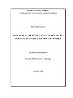
Fig. 11. Location update for node movement between square regions at different levels
The new location server region is in a square region, which is at a different level than the
level of node A’s previous square region. Therefore, the new location server region must
make a new entry in its location information database about the new fully qualified location
information of node A. This new location server region then needs to send the new relative
location information of node A to other location server regions within the new square
region. These other location servers previously had no location information about node A.
Therefore, they need to make new entries in their location information database about the
new relative location information of node A.
4.2 Location query
Suppose node S wants to send a data packet to a destination node D but the location
information of node D is unknown to S. Corresponding to three location update scenarios
three situations can evolve.
Mobile Ad-Hoc Networks: Applications
482
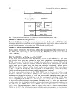
I. Destination D is within same sub-region at same level as of source S:
In this case the location server region that is in-charge of the sub-region contains the fully
qualified address of node D. The source node S sends the data packet to the location server
region. The location server region extracts the current x and y coordinate position of node D
from its fully qualified address and sends the data packet to node D at that location.
Sub-region 0
Sub-region 3
Sub-region 1
Sub-region 2
S
D
Fig. 12. Destination D is within same sub-region at same level as of source S
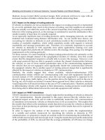
II. Destination D is within other sub-region at the same level as of source S:
In this case the source S sends the data packet to the assigned location server region of its
sub-region. But as the destination D is within a different sub-region, therefore, the location
server region of node S contains only the relative location information about destination D.
From this information, the location server region of node S can find the location server
region, which is currently containing the fully qualified address of node D. The location
server region of node S then sends the data packet forwarded by S, to that particular
location server region. This new location server region ultimately sends the data packet to
the destination node D.
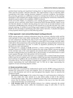
III. Destination D is within other square region at different level than that of source S:
The location server region now sends the data packet to the location server region of the
square region that is encompassing the current level square region. It also forwards the
packet to the location server region of the square region that is contained by the current
level square region. The location server regions at other levels now follow the previously
mentioned steps for location query. This process is continued until the destination node D is
found or the network boundary is reached. Thus, if the destination node falls within the
network boundary, the data packet is propagated from the source node S to the destination
node D through the intermediate location server regions.
Design and Analysis of a Multi-level Location Information Based
Routing Scheme for Mobile Ad hoc Networks
483
Sub-region 0
Sub-region 3
Sub-region 1
Sub-region 2
S D
Fig. 13. Destination D is within other sub-region at the same level as of source S
Sub-region 0
Sub-region 3
Sub-region 1
Sub-region 2
Sub-region 2
Sub-region 0
Sub-region 3
Sub-region 1
Sub-region 2
Sub-region 0
Sub-region 3
Sub-region 1
Sub-region 2
S
D
Fig. 14. Destination D is within other square region at different level than that of source S
Mobile Ad-Hoc Networks: Applications
484
5. Analysis of Layered Square Location Management (LSLM)
There are mainly two types of costs, which are important for any location management
scheme. These are - cost for location update and cost for location query. When a node
changes its position it must change its location information at the location server. The
number of packet forwarding operations it needs to perform per second, in order to
maintain fresh location information, is known as the location updation cost Cost
update
.
Similarly if a node wants to send a packet to a destination node whose location information
is unknown, in that case the sender node must perform location query, to find the location
information of the destination node. The number of packet forwarding operations that each
node needs to perform for the purpose of location query defines the location query cost
Cost
query
. There is also a third type of cost, which is known as the storage cost. The storage
cost Cost
storage
signifies the number of location records that each of the location servers needs
to store.
In the following sections we analyze these three types of costs for our proposed Layered
Square Location Management (LSLM) scheme.
5.1 Location updation cost [Cost
update
]:
In our proposed scheme, location update has been divided into three parts. As a
consequence, the cost for location update can also be divided into three parts - i>Cost for
location update for node movement within sub-region (Cost
update-intra-subregion
) ii>Cost for
location update for node movement between sub-regions (Cost
update-inter-subregion
) iii>Cost for
location update for node movement between square regions at different levels
(Cost
update-inter-level
).
Thus we can write,
Cost
update =
Cost
update-intra-subregion
+ Cost
update-inter-subregion
+ Cost
update-inter-level
D
Sub-region 0
Sub-region 3
Sub-region 1
Sub-region 2
Fig. 15. Distance D
Design and Analysis of a Multi-level Location Information Based
Routing Scheme for Mobile Ad hoc Networks
485
The cost for location update depends upon the amount of forwarding load, where
forwarding load is determined by the number of hops traversed by a packet during location
update operation. Thus the forwarding load, and as a consequence the cost will be greater
for a packet traveling a greater distance. Cost for location update for node movement within
sub-region (Cost
update-intra-subregion
) is basically the product of updation frequency and the cost
of updation of one location server region. The cost of updation of one location server region
is proportional to the average number of hops an update packet takes to reach the assigned
location server region. We denote this cost by Cost (1). We can approximate this cost by
considering the distance D=√2.2
l
.s; where l denotes level number (Fig. 15).
Let us denote z as the average progress for each forwarding hop, where z is a function of the
radio transmission range r
t
and the node density (γ) (Seung-Chul.et al., 2001). We assume
both r
t
and γ are constants. Therefore, z is also a constant. It is possible to derive the average
number of hops an update packet takes by D/z. If we consider the average velocity of a
node as v, and the transmission range of a node as r
t
,
then the updation frequency is v/r
t
.
Thus,
Cost
update-intra-subregion
= v/ r
t
. Cost (1)
L
And Cost (1) ∞ ∑ √2.2
l
.s/z
l=0
≈ √2.s.L/z.
If we assume S as the side length of the square region at the maximum level, i.e. L
th
level
square region, then, S ∞2
L
. Thus, L ∞ log S. Since, S ∞ √N, (N=Total Number of nodes in the
network), we have L ∞ log√N. Thus,
Cost
update-intra-subregion
= O (v.log√N). (1)
Cost for location update for node movement between sub-regions (Cost
update-inter-subregion
) is
the product of the boundary crossing rate (Ω) and the cost for updating the four location
server regions (Cost(4)). So,
Cost
update-inter-subregion
= Ω.
Cost (4).
The boundary-crossing rate is proved (Yu et al., 2004) to be proportional to v. The cost of
updating four location server regions can be approximated by 4(D
l
)/z. Thus
L
Cost (4) ∞ ∑4. √2.2
l
.s/z
l=0
≈ 4√2.s.L/z.
Therefore,
Cost
update-inter-subregion
= O (v.log√N). (2)
Similarly we can formulate Cost
update-inter-level
as
Cost
update-inter-level
= Ω.Cost (8).
Mobile Ad-Hoc Networks: Applications
486
We can approximate the cost of updating eight location server regions by 4(D
l
+ D
l-1
)/z.
Thus
L
Cost (8) ∞ ∑6. √2.2
l
.s/z
l=0
≈ 6√2.s.L/z.
Therefore,
Cost
update-inter-level
= O (v.log√N). (3)
Thus from “(1)”, “(2)” and “(3)” we have
Cost
update =
Cost
update-intra-subregion
+ Cost
update-inter-subregion
+ Cost
update-inter-level
= O (v.log√N).
5.2 Location query cost [Cost
query
]:
If a source node has some data to send to a destination node, the source node must first
query a location server region to get the current location information of the destination
node. The cost for this activity of querying the location information is known as location
query cost (Cost
query
). In order to calculate Cost
query
, we have to measure the expected
number of forwarding hops traveled by a query packet from the source node to its assigned
location server region, which can be approximated by D/z. Therefore, the expected query
cost is,
L
Cost
query
= ∑√2.2
l
.s/z
l=0
∞ H
= O (log√N).
5.3 Storage cost [Cost
storage
]:
In order to calculate the expected storage cost we need to find the average number of
records stored by a location server node in the network. Dividing the total number of
records stored in the network by the total number of nodes acting as location servers gives
us the average number of records. Each node in the network stores its address at the four
location server regions of its current layer of existence. Earlier we have mentioned that each
location server region is a square area having side length of r. Hence, the area covered by a
location server region can be expressed by r
2
. The average number of nodes (γ) is assumed
to be constant. Thus the average number of nodes serving as location servers within a
location server region is r
2
. γ. Now, the expected storage cost can be expressed as
Cost
storage
= (N.4. r
2
. γ)/(L. 4. r
2
. γ) = N/L,
where, N= Total number of nodes in the network; L= Maximum level number. Since L ∞
log√N; the expected storage cost, Cost
storage
= O (N).
Design and Analysis of a Multi-level Location Information Based
Routing Scheme for Mobile Ad hoc Networks
487
6. Conclusion
In this paper, we have presented Layered Square Location Management (LSLM), a novel
scheme for the management of location information of the nodes in mobile ad hoc network.
The effectiveness of a location management scheme depends on reducing the costs
associated with the major location management functions- location update and location
query. In case of a location service scheme we can reduce the location query cost by
employing various caching strategies which is not possible for location update cost. Keeping
track of only the exact location information, makes location update highly expensive due to
the high mobility of nodes. In our scheme by dividing the entire network area into L levels
of square regions and using multi-level location information, we have been able to provide a
unique way to reduce the cost associated with both location update and location query.
Further investigation on performance analysis of this scheme in different network scenarios
can be taken as extended work.
7. References
Amouris, K.N.; Papavassiliou, S. & Li, M. (1999). A position-based multi-zone routing
protocol for wide area mobile ad-hoc networks. In Proceedings of the IEEE Vehicular
Technology Conference (VTC), pages 1365-1369
Chen, T. W. & Gerla, M. (June 1998). Global State Routing: A New Routing Scheme for Ad
Hoc Wireless Networks, Proceedings of IEEE ICC 1998, pp. 171-175
Cheng, Christine. T.; Lemberg, H. L.; Philip, Sumesh. J.; Berg, E. van. den. & Zhang, T.
(March 2002). SLALoM: A scalable location management scheme for large mobile
ad-hoc networks. In Proceedings of IEEE WCNC
Chiang, C. C.; Wu, H. K.; Liu, W. & Gerla, M. (April 1997). Routing in Clustered Multi-Hop
Mobile Wireless Networks with Fading Channel, Proceedings of IEEE SICON 1997,
pp. 197-211
Clausen, T. H.; Hansen, G.; Christensen, L. & Behrmann, G. (September 2001). The
Optimized Link State Routing Protocol, Evaluation Through Experiments and
Simulation, Proceedings of IEEE Symposium on Wireless Personal Mobile
Communications 2001
Dube, R.; Rais, C. D.; Wang, K. Y. & Tripathi, S. K. (February 1997). Signal Stability-Based
Adaptive Routing for Ad Hoc Mobile Networks, IEEE Personal Communications
Magazine, pp. 36-45
Garcia-Luna-Aceves, J. J. & Spohn, M. (October 1999). Source-Tree Routing in Wireless
Networks, Proceedings of IEEE ICNP 1999, pp. 273-282
Gerla, M.; Pei, G. & Hong, X. (August 2000). Lanmar: Landmark routing for large scale
wireless ad hoc networks with group mobility. In Proceedings of the First IEEE/ACM
Workshop on Mobile Ad Hoc Networking and Computing (MobiHOC)
Haas, Z. J. (October 1997). The Routing Algorithm for the Reconfigurable Wireless
Networks, Proceedings of ICUPC 1997, vol. 2, pp. 562-566
Haas, Z. J. & Pearlman, M. R. (August 1998). “The zone routing protocol (ZRP) for ad hoc
networks (Internet Draft)”
Iwata, A.; Chiang, C. C.; Pei, G.; Gerla, M. & Chen, T. W. (August 1999). Scalable Routing
Strategies for Ad Hoc Wireless Networks, IEEE Journal on Selected Areas in
Communications, vol. 17, no. 8, pp. 1369-1379
Mobile Ad-Hoc Networks: Applications
488
Joa-Ng, M. & Lu, I. T. (August 1999). A Peer-to-Peer Zone-Based Two-Level Link State
Routing for Mobile Ad Hoc Networks, IEEE Journal on Selected Areas in
Communications, vol. 17, no. 8, pp. 1415- 1425
Johnson, David. B. & Maltz, David. A. (1996). ( Dynamic source routing in ad hoc wireless
networks. In Imielinski and Korth, editors, Mobile Computing, volume 353. Kluwer
Academic Publishers
Li, J.; Jannotti, J.; Couto, D. De.; Karger, D. & Morris, R. (August 2000). A scalable location
service for geographic ad-hoc routing. In Proceedings of ACM MobiCom, pages
120.130
Murthy, S. & Garcia-Luna-Aceves, J.J. (October 1996). An efficient Routing Protocol for
Wireless Networks. ACM Mobile Networks and App. Journal, Special Issue on Routing
in Mobile Communication Networks
Park, V.D. & Corson, M.S. (April 1997). A Highly Adaptive Distributed Routing Algorithm
for Mobile Wireless Networks. Proceedings of IEEE INFOCOM’97, Kobe, Japan
Perkins, Charles. E. & Bhagwat, Pravin. (August 1994). Highly dynamic Destination-
Sequenced Distance-Vector routing (DSDV) for mobile computers. In Proceedings of
the SIGCOMM ’94 Conference on Communications Architectures, Protocols and
Applications, pages 234–244
Perkins, Charles. & Royer, Elizabeth. (1999). Ad-hoc on-demand distance vector routing. In
Proceedings of IEEE Workshop on Mobile Computing Systems and Applications
Seung-Chul.; Woo, M. & Singh, Suresh. (2001). Scalable routing protocol for ad hoc
networks. Wireless Networks, 7(5):513-529
Sinha, P.; Sivakumar, R. & Bharghavan, V. (August 1999). CEDAR: A Core Extraction
Distributed Ad Hoc Routing Algorithm, IEEE Journal on Selected Areas in
Communications, vol. 17, no. 8, pp. 1454-1466
Sisodia, R. S.; Manoj, B. S. & Murthy, C. Siva. Ram. (March 2002). A Preferred Link-Based
Routing Protocol for Ad Hoc Wireless Networks, Journal of Communications and
Networks, vol. 4, no. 1, pp. 14-21
Su, W. & Gerla, M. (December 1999). IPv6 Flow Handoff in Ad Hoc Wireless Networks Us-
ing Mobility Prediction, Proceedings of IEEE GLOBECOM 1999, pp. 271-275
Toh, C. K. (March 1997). Associativity-Based Routing for Ad Hoc Mobile Networks, Wireless
Personal Communications, vol. 4, no. 2, pp. 1-36
Xue, Y.; Li, B. & Nahrstedt, K. (2001). A scalable location management scheme in mobile ad-
hoc networks. In Proceedings of the IEEE Conference on Local Computer Networks (LCN
'01)
Yu, Yinzhe.; Lu, Guor-Huar. & Zhang, Zhi-Li. (2004). “Enhancing location service scalability
with HIGH-GRADE,” Dept. of Comp. Sci. & Eng., University of Minnesota,
Technical Report TR-04-002
0
Power Control in Ad Hoc Networks
Muhammad Mazhar Abbas and Hasan Mahmood
Quaid-i-Azam University
Pakistan
1. Introduction
In this chapter, we present the power control techniques used in ad hoc networks.
Traditionally, the power control has been implemented and used effectively in cellular
networks. While the use of transmission power control in infrastructure based networks has
proven to work well and improve performance, the application of power control techniques
to ad hoc networks has many challenges and implementation complexities (Chauh & Zhang,
2006) (Basagni et al., 2004). The power control is of great significance in ad hoc networks
because of their organizational structure and lack of central management. With the
implementation of effective power control techniques, the ad hoc network can improve their
vital parameters, such as power consumption, interference distribution, throughput, routing,
connectivity, clustering, backbone management, and organization (Basagni et al., 2004).
We discuss several power control algorithms commonly used in ad hoc networks to get insight
of power control techniques and their effectiveness. Most of the algorithms are adapted from
cellular networks, modified accordingly, and proposed for ad hoc networks. Moreover, we
argue the enhancement in performance of ad hoc networks with the use of these power control
algorithms.
The power control requirements vary depending on the physical and network layer
implementation of ad hoc networks (St¨uber, 2002). We show the application of the
prevailing power control algorithms to different physical layer models and discuss their
performance. The application to CDMA based networks is emphasized as these types of
networks have strict power control requirements and the performance is severely degraded
without appropriate power control. In cellular networks, the power control requirements are
stringent, especially in multiple access technologies. The appropriate allocation of power to
the transmitters facilitates interference control and saves energy.
The near-far effect starts to dominate as the transmission power levels are not properly
managed. The advantage of cellular networks over ad hoc networks is the presence of central
management, and as a consequence, the uplink power control can be achieved. This is in
contrast to ad hoc networks, which lack central management and most of the nodes are in
peer to peer configuration (Blogh & Hanzo, 2002).
In addition, transmit power control is a cross layer design problem affecting all layers of
the OSI model from physical layer to transport layer (Jia et al., 2005). In general, power
conservative protocols are divided into two main categories: transmitter power control
protocols and power management algorithms. Second class can be further divided into MAC
layer protocols and network layer protocols (Ilyas, 2003).
22
2 Theory and Applications of Ad Hoc Netw orks
At the end of the chapter, we discuss the concept of joint power control and routing
in ad hoc networks. Power can be controlled in ad hoc networks by choosing optimal
routes. The existing routing protocols may be classified as, uniform, non-uniform, proactive,
reactive, hybrid, source, and non-source routing protocols (?Chaudhuri & Johnson, 2002). To
further explain joint power control and routing techniques, we discuss a Minimum Average
Transmission Power Routing (MATPR) technique (Cai et al., 2002), which implements a
power control routing protocol using the concept of blind multi-user detection to achieve
the task of minimum power consumption. The Power Aware Routing Optimization (PARO)
technique (Gomez et al., 2003), a protocol for the minimization of transmission power in ad
hoc networks, is based on the concept of node to node power conservation using intermediate
nodes, usually called redirectors. PARO is efficient in both static and dynamic environments
and is based on three main operations: overhearing, redirecting, and route maintenance.
2. Cellular networks
The wireless cellular networks require a fixed and well defined infrastructure. This type of
network infrastructure is suitable to efficiently manage the network operations. Generally
the network can be managed and operated by a central operations point. In the field, the
the physical parameters, such as transmission frequency, resource allocation, and power
control parameters are monitored and controlled by base station which have fixed location.
We focus on power control for these types of configurations in order to study and analyze
implementation to ad hoc networks.
Power control is a necessary feature in cellular communication networks with multiple access
technologies. Power control has many management features such as interference control,
energy saving, and connectivity (Almgren et al., 2009). In power control mechanism each
user transmits and receives at an appropriate energy level, i.e., the transmission powers are
controlled in such a way that the interference is minimized, while achieving sufficient quality
of service (Lee, 1991).
In the absence of power control, the near-far effect is introduced as all the mobile users
transmit at same power level or at a level which is not suitable at receivers in the network.
In other words, the transmitters close to the base station create interference to neighboring
users which are in the vicinity. In the absence of power control, the system capacity degrades
as compared to other wireless systems (Hanly & Tse, 1999). The power control also increases
the battery life by using a minimum required transmission power and is equally important in
both uplink and downlink transmissions. In uplink transmission, the near-far effect problem
is created as the signals of mobile propagate through different channels before reaching their
corresponding base station (Moradi et al., 2006). The purpose of power control is to allow all
mobile signals to be received with same power at the base station. Uplink power control
enhances capacity of networks (Gilhousen et al., 1991). On the other hand, in downlink
transmission, the near-far effect problem is not as important, because signals from the base
station reach the mobile station while propagating through same channel (Lee et al., 1995).
Uplink power control algorithms achieve their functions through open loop and closed loop
power control, which can be further divided into closed outer loop power control and closed
inner loop power control. In open loop power control, the mobile user adjusts its transmission
power based on the received signaling power from the base station (Chockalingam & Milstein,
1998). In closed-loop power control, based on the measurement of the link quality, the base
490
Mobile Ad-Hoc Networks: Applications
Po wer Control in Ad H oc Networks 3
station sends a power control command instructing the mobile to increase or decrease its
transmission power level and sets the target signal-to-interference ratio (SIR)tosuchalevel
that sufficient quality of service is guaranteed (Rintam¨aki, 2002).
Power can be controlled in a centralized or distributed fashion. In centralized form a controller
manages the information of all the established connections and channel gains, and controls
the transmission power level (Grandh et al., 1993). While in the distributed form a controller
controls only one transmitter of a single connection. It controls transmission power based
on local information such as the signal to interference ratio and channel gains of the specific
connection. Distributed form of power control is easy to use in common practice because it
does not require extensive computational work (Zender, 1993).
Although we aim to discuss power control techniques for wireless ad hoc networks, it
is important to get insight for the similar techniques used in cellular networks. These
techniques were initially applied to cellular networks, and with the advent of ad hoc network
were adapted and modified to meet new requirements. Some of the basic power control
algorithms are presented below which are related to wireless cellular networks and their
implementations.
2.1 Power control as eigen value problem
In the era of 1980s the concept of Signal to Interference Ratio (SIR) balancing in power
control algorithms for cellular networks based on Code Division Multiple Access (CDMA)
and other technologies were used by researchers (Nettleton, 1980) (Nettleton & Alavi, 1983)
(Alavi & Nettleton, 1982). Initially, the power control problem was focused and treated as an
eigen value problem with a non negative matrix G and corresponding balance power vectors
p
u
and p
d
which satisfy the eigen value problem as
Gp
u
=[(1 + γ
u
)/γ
u
]p
u
(1)
and
G
T
p
d
=[(1 + γ
d
)/γ
d
]p
d
(2)
where γ
u
and γ
d
are desired uplink and downlink SIRs. By taking λ(G) as eigen value of G a
solution to the above problem is given as
[(1 + γ
u
)/γ
u
]=[(1 + γ
d
)/γ
d
]∈ λ(G) (3)
Another solution to SIR balancing problem is given as
γ
u
= γ
d
= 1/(ρ − 1) (4)
where spectral radius ρ is such that ρ
> 1.
Iterative methods are very effective in solving these type of problems. One approach
(Foschini & Miljanic, 1993) to solve the above eigen value problem iteratively is by solving
liner algebraic equations, represented as AP
= b,whereP =[p
1
, p
2
, p
N
]
T
,and
P
(k + 1)=(1 − A)P(k)+b (5)
This algorithm converges and the method use derivative named as surrogate derivative and
concludes that their algorithm is converging synchronously.
491
Power Control in Ad Hoc Networks
4 Theory and Applications of Ad Hoc Netw orks
A generalized frame work for convergence is given in (Yates, 1995). By using proper power
control, the interference is eliminated and we get iteration as
p
i
(k + 1)=γ
tar
i
(k)p
i
(k)/γ
i
(k) (6)
where p
i
is the power of i
th
user and γ
tar
i
is the target SIR
2.2 D istributed power control techniques
The Distributed Power Control (DPC) algorithm is applied at individual nodes in the network
and the objective is to converge system power allocations to a suitable level (Grandhi et al.,
1994). This can be accomplished by using feedback power control (Ariyavisitakul, 1994). In
this method the power is adjusted in steps which may have fixed or variable size. It is seen
that the performance of a power control algorithm with fixed step size and variable step size
is almost the same. In addition, the higher power control rate can accommodate the effect of
fast fading.
With the implementation of distributed power control, the SIRof the system can be controlled
and managed to some extent. As a result, the outage probability of an individual link or a set
of links can be reduced or entirely eliminated. The implementation of this type of method
requires a distributed power control algorithm which reduces the outage probability to zero
by keeping SIR above threshold value (Zander, 1992).
In another approach, a smaller balancing systems can be constructed by turning the
transmitter of cells off so the outage probability is minimized. In some scenarios, if the value
of SIRfor a mobile is less than threshold value then outage probability is reduced and mobile
is dropped from network (Wu, 1999). This improves the remaining network SIR.
An optimal SIRbased distributed power control technique can be used by unconstrained and
constrained optimization (Qian & Gajic, 2003). The theme of this algorithm is to establish a
proportionality between transmission power and the error between the actual SIR and the
desired SIR. Difference of transmission power from time step k to k
+ 1isgivenas
ΔP
i
(k + 1)=P
i
(k + 1) − P
i
(k) (7)
The error between desired SIR and actual SIR is given as
e
i
(k)=γ
des
i
− γ
i
(8)
Then the proposed algorithm is described as
ΔP
i
(k + 1)=α
i
(k)e
i
(k) (9)
where α
i
(k) is the gain. Thus power allocation is given as
P
i
(k + 1)=P
i
(k)+α
i
(k)(γ
des
i
− γ
i
) (10)
2.3 D iscrete time dynamic optimal power control
In this method, the reverse link system information is used for power control. A cost function,
consisting of weighted sum of powers and some additional parameters is defined. An optimal
power control law is presented based on a cost function comprising of weighted sum of power,
power update information, and SIR error. It is also assumed that there is no significant change
492
Mobile Ad-Hoc Networks: Applications
Po wer Control in Ad H oc Networks 5
in SIRfrom one step to the next. For this purpose, a technique named as discrete time dynamic
optical control is implemented (Koskie & Gajic, 2003). The general cost function and sufficient
conditions for optimality are defined as
J
[N]=g(x[N]) +
N−1
∑
K=0
L(x[k], u[k], k) (11)
and
H
xx
H
xu
H
T
xu
H
uu
> 0, H
uu
> 0 (12)
where J is the controller, L is the cost function and H is the hamiltonian. Some of the different
optimal controllers for three cost functions are
J
I
=(1/2)
K
∑
k=0
(qe
2
[k ]+su
2
[k ]) for cheap power cost (13)
J
II
=(1/2)
K
∑
k=0
(qe
2
[k ]+2rp[k]+su
2
[k ])for linear power cost (14)
J
III
=(1/2)
K
∑
k=0
(qe
2
[k ]+rp
2
[k ]+su
2
[k ])for quadratic power cost (15)
This method considerably saves power and improve quality of service.
2.4 Linear and bilinear power control techniques
The optimization of power conservation results in improved SIR distribution for the entire
network. Although these optimizations are based on some estimates, as a consequence, errors
are introduced in the actual results (Gajic et al., 2004).
The power control techniques named as linear and additive power updates algorithm and
bilinear control algorithm are based on optimization of SIR error. It can be seen that mobile
power is updated by using a distributive linear control law, given as
P
i
(k + 1)=P
i
(k)+U
i
(k) (16)
where i
= 1,2, n. By minimizing SIR error and after other calculations the optimized power
updates can be obtained as
P
∗
i
(k + 1)=P
∗
i
(k)+U
∗
i
(k) (17)
P
∗
i
(k)=γ
tar
i
I
i
[P
−
i
∗
(k)] /g
ii
(18)
Where P
∗
i
is the optimized power. In the second algorithm, bilinear control law is used for
update of power as
P
i
(k + 1)=P
i
(k)U
i
(k) (19)
where i
= 1,2, n, and corresponding optimized power is same as in above case.
493
Power Control in Ad Hoc Networks
6 Theory and Applications of Ad Hoc Netw orks
2.5 Power control technique based on relaxation method
This method is particularly useful in networks with multiple access technology, such as
CDMA. A relaxation method can be used in solving iterative power control techniques. Two
common techniques for iterative solution of power control problems can be used effectively
with relaxation method. Application to Jacobi iteration method and Gauss Siddel iteration
method for solution of power control problem, by introducing a relaxation parameter in these
techniques, is presented as a modified Jacobi iteration
P
i
(k + 1)=[1 − β + β
γ
tar
i
γ
i
(k)
]
P
i
(k) (20)
and modified Gauss Siddle iteration
P
i
(k + 1)=[1 − β + β
γ
tar
i
γ
i
(k, k + 1)
]
P
i
(k) (21)
The Gauss Siddle iteration with relaxation parameter β is more efficient than Jacobi iteration
technique for solution of power control problem. The algorithms implemented by relaxation
method converge faster than simple distributed power control algorithm (Siddiqua et al.,
2007).
2.6 D istance based power control technique
The distance between transmitters and receivers can be estimated in a wireless networks. The
attenuation of the signals is proportional to the distance which they travel. Therefore, if the
information about the distances is know in real time or a prior, the power can be adjusted
efficiently (Nuaymi et al., 2001). If a base station is present, the transmit power of each mobile
station can be controlled by using distance information between base station and mobile
stations. This algorithm computes the transmitted power P
m
of a mobile node m as
P
m
= kx
n
a
m
m
(22)
where
x
a
m
m
=
d
a
m
m
rR
,ifd
a
m
m
> d
min
d
min
R
,ifd
a
m
m
≤ d
min
(23)
where R is the base to mobile maximum distance and d
a
m
m
is the distance between mobile and
assigned base station.
2.7 K alman filter based power control technique
In an uplink closed loop power control algorithm based on Kalman filter technique, the
controller or a base station estimates SIR in a closed loop system (Rohi et al., 2007). The SIR
can be estimated by any suitable method. The outage probability calculated by this method
is smaller as compared to others. According to algorithm details, the base station estimates
the SIR for a user and provide as input to Kalman predictor. Its output is compared with the
desired SIR and the difference is quantized by a PC M. The transmitted power of user is then
updated and SIR estimation is given as
SIR
∗
n+1
= SIR
∗
n
+ αΔSIR
∗
n
+ ω
n
(24)
494
Mobile Ad-Hoc Networks: Applications
Po wer Control in Ad H oc Networks 7
and
ΔSIR
∗
n
= SIR
∗
n
− SIR
∗
n−1
(25)
The outage probability is given as P
0
= P
r
(SIR
r
< SIR
0
).WhereSIR
r
is measured at base
station and SIR
0
is the minimum value of SIR for achieving desired BER.
2.8 Power control technique based on linear quadratic control theory
The state-space formulation and linear quadratic control technique can be used to solve the
problem of power control by considering each mobile to base station link as an independent
subsystem described as
S
i
(n + 1)=S
i
(n)+V
i
(n) (26)
where
S
i
(n)=P
i
(n)/I
i
(n) (27)
and
V
i
(n)=U
i
(n)/I
i
(n) (28)
and
I
i
(n)=
Q
∑
j=i
P
i
W
ij
+ n
i
/G
ki
(29)
The input to each subsystem U
i
(n) depends on the total interference produced by other users
plus the noise in the system and each S
i
(n) track is made equal to the threshold value of SIR
(Osery & Abdallah, 2000). For the discrete case the new state is given by
ς
i
(n + 1)=ς
i
(n)+e
i
(n) (30)
where error e
i
(n)=S
i
(n) − γ
∗
. Each subsystem can now be expressed as a second-order linear
state-space system as
X
i
(n + 1)=
e
i
(n + 1)
s
i
(n + 1)
=
11
01
X
i
(n)+
0
1
V
i
(n) (31)
The feedback controller V
i
(n)=−[k
ς
k
s
]x
i
(n)+k
s
γ
∗
,where[k
ς
k
s
] is the gain matrix which
are found by solving the Riccati equation. If the right feedback gains
[k
ς
k
s
] is chosen, the
steady-state S
i
(n) will go to the threshold SIR. To find the optimum feedback control for the
state-space representation given above, the Linear Quadratic Control theory is used. After the
gain matrix
[k
ς
k
s
] is found, the power control can be expressed as
P
i
(n + 1)=min [P
i
,S
i
(n + 1)I
i
(n)] (32)
The method assures that the maximum transmission power of the mobile i will not be
exceeded. This method reaches a zero outage probability with less iterations than other
distributed power control methods. This approach was also found to be more effective in
handling a large number of mobile stations in the system.
495
Power Control in Ad Hoc Networks
8 Theory and Applications of Ad Hoc Netw orks
2.9 Power control technique based on utility and pricing
The power control algorithm can be implemented in a distributed fashion based on utility
and pricing concepts (Shah et al., 1998). The efficiency of this protocol can be improved in low
BER and high SIR conditions. The formula of SIR of user j at base station k is given as
γ
=
W
R
h
jk
p
j
∑
∀i =j
h
ik
p
i
+ σ
2
k
(33)
In this method, by introducing a pricing factor the utility is maximized and as a result helps
in power control problem. A general utility function which is a monotonically increasing
function of SIR is given as
u
j
=
E
p
j
Rf(γ) (34)
Where f
(γ) is a measure of efficiency of protocol. The power control problem is considered
as a cooperative power control game. The user maximizes its utility at equilibrium point
with maximum SIR value as Max u
i
(p
1
, p
2
, p
N
), ∀i = 1,2, N,and f (γ
∗
)=γ
∗
f (γ
∗
).
We can also consider a monotonically increasing pricing function, F
= βp
j
, which is assumed
to depend upon a cost function, given as,
c
ij
= −
∂u
i
∂p
j
p
j
(35)
and some inequalities,
p
∗
1
< p
∗
2
< < p
∗
N
(36)
u
∗
1
> u
∗
2
> > u
∗
N
(37)
c
∗
1
< c
∗
2
< < c
∗
N
(38)
A distributed power control algorithm for a wireless cellular system based on sigmoid like
utility function can also be implemented (Xiao et al., 2003). In this algorithm, the power
control problem is considered as a multi player non-cooperative game. This algorithm is valid
for both voice and data users. The value of SIR for user i with transmission power P can be
written as
SIR
i
=
G
ii
P
i
∑
j=i
G
ij
P
j
+ σ
i
(39)
The main goal of this algorithm is to maximize the net utility by transmission power
adjustment and softening the hard SIR requirements as
NU
i
(SIR
i
, P
i
)=U
i
(SIR
i
) − C
i
(P
i
) (40)
where C
i
(P
i
)=α
i
P
i
is assumed cost function of power for the user i. The power control
problem is then defined as max
P≥i
NU
i
. By solving above equation the optimal power for
user i is
496
Mobile Ad-Hoc Networks: Applications
Po wer Control in Ad H oc Networks 9
ˆ
P
i
=
R
i
G
ii
f
−1
i
(α
R
i
G
ii
)=
R
i
G
ii
SIR
i
(41)
After introducing the iteration factor the above equation can be written as
ˆ
P
i
(K + 1)=
R
i
(K)
G
ii
(K)
SIR
i
(K)=P
i
(K)
SIR
i
(K)
SIR
i
(K)
(42)
Thus, by using utility based power control protocol, a user can control its power by decreasing
its SIR and even turn off transmission during heavily loaded network.
2.10 Opportunistic power control technique
In this distributed opportunistic power control algorithm, the transmission power depends
on channel gain by observing feedback from the receiver. The transmission rate is managed
by SIR at the receiver (Leung & Sung, 2006). The SIR of a terminal i in a cellular system
comprising of N mobile terminals can be written as γ
i
=
P
i
R
i
,whereR
i
is the effective
interference to terminal i,andisgivenas
R
i
=
∑
j=i
G
ij
+ σ
i
G
ii
(43)
and the power of the terminal i is upgraded as
P
n+1
i
= I
i
(R
n
i
, P
n
i
) (44)
The proposed opportunistic power control algorithm is given as
I
opp
i
(R
n
i
)=
ς
i
R
n
i
(45)
This algorithm converges and equation P
n
i
R
n
i
= ς
i
is satisfied. The transmission power of
terminal i varies directly with ς
i
.
2.11 Power control technique based on simple prediction Method
A simple prediction is sometimes useful for power control in wireless networks (Neto et al.,
2004). This approach can be used to implement a distributed power control algorithm, based
on simple prediction method, and by considering both path gain and SIR as time varying
functions using Taylor series. Discrete-time SINR is given as
γ
i
(k)=
g
i
(k)p
i
(k)
I
i
(k)
(46)
where p
i
(k)=
I
i
(k)γ
i
(k)
g
i
(k)
is known as necessary transmission power. The transmission power at
instant k
+ 1 is given by using Taylor series as
p
i
(k + 1)=γ
t
ˆ
I
i
(k + 1)
ˆ
g
i
(k + 1)
=
γ
t
2I
i
(k) − I
i
(k − 1)
2g
i
(k) − g
i
(k − 1)
(47)
497
Power Control in Ad Hoc Networks
10 Theory and Applications of Ad Hoc N etworks
3. Ad hoc networks
Wireless networks without any fixed infrastructure are called ad hoc networks, also often
called as infrastructure less networks. Generally, ad hoc wireless networks are self-creating,
self-organizing, and self-administrating networks (Cayirci & Rong, 2009). Ad hoc network
consists of mobile nodes which communicate with each other through wireless medium
without any fixed infrastructure. Nodes in mobile ad-hoc network are free to move and
organize themselves in an arbitrary fashion. The nodes in a mobile ad hoc network (MANET)
must collaborate amongst themselves and each node may acts as a relay when required.
Mobile ad hoc networks have a fully decentralized topology and they are dynamically
changing (Jindal et al., 2004). Ad hoc networks are very popular in military applications for
many years. The concept of ad hoc networks was first used in commercial area in 1990s, at
the same time, the idea of a collection of mobile nodes was originated. In the mid of 1990s
some routing protocols were standardized by a commission known as Internet Engineering
Task Force (IETF). First standard IEEE802.11 for wireless network was introduced in 1997. The
latest standard is faster and applied for longer communication. Today, ad hoc networks are
attractive and challenging topic of research due to its tremendous applications (Perkins, 2001).
The most popular applications of ad hoc networks are temporary communication networks,
relief operations, operations in congested and small areas (Ramanathan & Redi, 2002).
Ad hoc networks have many challenges which includes high error probability of transmission,
limited capacity, hidden and exposed terminals problem, interference, mobility, node failures,
topology maintenance, self healing, node search, synchronization, transmission reliability, and
congestion control etc. (Goldsmith & Wicker, 2002).
3.1 Importance of po wer control in ad hoc networks
Unlike cellular networks, in ad hoc networks the power control is not trivial and is usually
managed in a distributed fashion. The nodes in the ad hoc network communicate with all
other nodes by sending packets to the neighboring nodes. The choice of an appropriate power
level for packets at a particular node is very crucial matter, as it indirectly effects the physical
layer, network layer, and transport layer of the system by determining the quality of received
signal, range of transmission and magnitude of interference respectively (Kawadia & Kumar,
2005). The nodes in ad hoc networks use different modes of operation such as transmit mode,
receive mode, idle mode and sleep mode. As a result, these different types of nodes have
different power consumption requirements (?).
Power consumption of ad hoc networks can be controlled either by controlling transmission
power or by choosing optimal routs for transmission. Transmit power control is a cross
layer design problem affecting all layers of the OSI model from physical layer to transport
layer (Jia et al., 2005). In general power conservative protocols can be divided into two main
categories as transmitter power control protocols and power management algorithms. Second
class can be further divided into MAC layer protocols and Network layer protocols (Ilyas,
2003). In the subsequent sections, we present the details of some of these protocols.
4. Power control techniques in ad hoc networks
The power control issue is one of the major challenges prevailing in ad hoc networks. There
are many power control algorithms presented by various authors and researchers. Some of
498
Mobile Ad-Hoc Networks: Applications
Po wer Control in Ad H oc Networks 11
these algorithms are discussed in this chapter. We begin by presenting algorithms which are
based on 802.11 medium access layer, then discuss some of the challenges faced by CDMA
networks as in these types of networks, power control is an essential component. In addition,
power control techniques at network layer are also presented. These power control methods
are jointly implemented with routing protocols and clustering configurations.
4.1 Simple modifications to 802.11
The 802.11 MAC standard is slightly modified and adapted in order to obtain a distributed
power control loop based algorithm which results in lower energy consumption and higher
throughput. In this algorithm, in contrast to the original IEEE 802.11 MAC protocol,
the transmissions occur at different power levels which are chosen by the algorithm
(Agarwal et al., 2001). The main purpose of the algorithm is to calculate a minimum transmit
power level for each node to successfully transmit to neighboring nodes. During transmission,
a ratio of the signal strength of the last received message to the minimum acceptable signal
strength at the node currently transmitting the message is included in the CTS and DATA
message headers. The receiver encodes the ratio of received signal strength of RTS message to
minimum acceptable signal strength in the header of CTS reply message.
The transmitter will also encode into it the ratio with respect to CTS upon transmitting the
DATA message. In this way RTS-CTS-DATA-ACK exchange provides an opportunity to both
receiver and transmitter to inform each other not only about their signals strength but also
about their transmit power levels. Each node maintains a small table with fields cf-pwr,
dr-pwr and a count down timer field. The field cf-pwr maintains an exponential weighted
average history of the received signal strength ratio received from each neighbor and the
dr-pwr field maintains an exponential weighted average (EWA) history of the cf-pwr field
at instances when packet loss occurred. Upon receiving a CTS or DATA message from a node
its cf-pwr field in the table is updated by decreasing the transmit power level by one, unless
the countdown timer shows zero value. The dr-pwr field in the table is updated by increasing
transmit power level by one for the timeout during wait for CTS, DATA or ACK message.
A power control scheme based on modifications to BASIC power control scheme (CTS-RTS
hand shake), can be implemented which saves power without degrading throughput
(Jung & Vaidya, 2002). In this algorithm just like BASIC power control scheme RTS and
CTS, messages are sent at maximum power level P
max
while DATA and ACK messages are
sent with minimum power level. The novelty of this protocol is that ACK-DATA collision
avoidance can be made possible by transmitting DATA with maximum power level for a short
period so that nodes in CS zone can sense it. P
max
is achieved periodically during transmission
of DATA. The nodes which may interfere with ACK reception stops their transmission by
observing that system is busy and power is saved.
In another modification (Lin & Lau, 2003), a protocol for power control named as PCMAC is
implemented. This protocol overcomes the problems created by asymmetrical links efficiently.
The IEEE 802.11 standard protocol is modified by introducing an extra channel for power
control. In contrast to the BASIC scheme for power control, in PCMAC protocol RTS, CTS,
DATA, and ACK transmission occur at minimal necessary power level while the broadcast
packets at maximal power level. During reception of DATA, the receiver calculates the noise
power level by estimating the noise and signal strength. It then informs the neighboring
terminals with this information by using power control channel. Keeping in view this
499
Power Control in Ad Hoc Networks
12 Theory and Applications of Ad Hoc N etworks
information the neighboring terminals take any suitable action. This algorithm replaces the
four way handshake by three way hand shake. Also, each terminal manages the three tables
named as sent table, receive table for data packet transmission, and a power history table
maintaining the record of necessary power level to reach other terminals. This necessary
power level is calculated as P
nec
= Rx
th
P
T
/E,WhereE is the received signal strength, P
T
,
the power level at which a packet is transmitted, included in the RTS, CTS and broadcast
packet head.
4.2 Link collision avoidance technique
In Asymmetric Link Collision Avoidance (ALCA) based power control protocol the power
levels are managed by the announcement of the Current Transmission Duration Information
(CTDI) through N different carrier durations (CD) (Pires et al., 2005). This protocol overcomes
the problem of DATA, ACK frames collision in BASIC power control scheme due to
asymmetric links. ALCA is based on two major steps. Firstly the transmitting node computes
the CTDI and then allows the nodes in CS-Zone (CSZ) to recover required CTDI by choosing
an appropriate CD from N different CDs. Secondly, the terminal in the CSZ finds a suitable
extended inter frame space (EIFS) value based on CD extracted by the DATA carrier. This
protocol saves power considerably.
4.3 Power control dual channel protocol
The power control dual channel (PCDC) protocol permits simultaneous interference limited
transmissions in the neighboring area of receiver by modifying typical RTS-CTS handshake
process in mobile ad hoc networks (Muqattash & Krunz, 2004). This protocol gives much
importance to the network layer and MAC layer interaction as power control issue is
considered a joint MAC and network layer problem. The MAC layer controls the transmission
power of route request (RREQ) packets and affects the network layer. As it is evident from the
name, there are two main channels in protocol - data and control channel. The control channel
has further two sub channels named as RTS-CTS channel and ACK channel. This protocol is
based on the following assumptions:
i. Channel gain remains stationary during transmission of DATA packets.
ii. The gain between two nodes remain same in both sides.
iii. Data and control packets observe same gain between a pair of nodes.
This protocol is distributed in nature and has advantages over other protocols because of
the availability of reserved channels. Although functioning of the protocol has relatively
stringent assumptions, a relatively smooth and better performance can be achieved under
normal channel conditions.
4.4 Power control MAC protocol
This protocol uses an access window and improves the network throughput at low
energy consumption by allowing multiple transmissions (Muqattash & Krunz, 2005). It is a
distributed, asynchronous and adaptive power control protocol and is named as POWMAC
which is based on single channel and single transceiver design. The novel features of
POWMAC are described as:
500
Mobile Ad-Hoc Networks: Applications
Po wer Control in Ad H oc Networks 13
i. Collision avoidance information (CAI) is included in control packets instead of simple
RTS/CTS control packets.
ii. Required transmission power is calculated at the intended receiver.
iii. Some CTS and Decide-to-Send (DTS) packets are transmitted towards the potentially
interfering terminals.
iv. An access window (AW) is introduced which stops the transmission of DATA packets for
a short period and reduces the collisions between control and data packets by informing
the transmitters about ensuing transmission.
4.5 D istributed correlative power control technique
The correlative power control can be described as a transmitting node that predicts the
interference by using a prediction filter after observing the interference around it. It also
includes this information with RTS message. The receiving node assigns a power to CTS
by observing this included predicted interference. The receiver repeats the whole procedure
and then sends CTS message along with predicted interference to transmitter. The transmitter
then assigns power to DATA by observing this predicted value of interference included in
CTS message. The same procedure is adopted before sending DATA and ACK messages
by transmitter and receiver (Alawieh et al., 2007). The minimum transmission power can be
calculated as P
min
= k/Gain, where the channel loss Gain can be measured as a ratio of the
received and transmitted powers P
r
and P
t
. The received signal power can be given as
P
r
= P
t
r
−4
G
2
h
2
10
/10
(48)
Where r is the distance between two nodes, h is the height of the antenna, G is the antenna
gain and
is shadowing component. The transmission power of CTS is given as
P
CTS
= max(P
min
,ζ × I/Gain) (49)
The transmission power of DATA is given as
P
DATA
= max(P
min
,ζ × I
+
/Gain) (50)
The transmission power of ACK is given as
P
ACK
= max(P
min
,ζ × I
++
/Gain) (51)
Where I is the predicted interference plus noise power.
4.6 A daptive power control techniques
The adaptive power control technique uses a two ray ground propagation model (Zhang et al.,
2005a). This adaptive power control algorithm is based on the relationship between
transmission powers of RTS-CTS, CTS-DATA, and DATA-ACK pairs using single channel
setup. The relationship between transmit power P
t
and receive power P
r
canbewrittenas
P
r
= P
t
∗ G
t
∗ G
r
∗ h
2
t
∗ h
2
r
/d
4
(52)
where h
t
and h
r
are the heights, and G
t
and G
r
are the gains of transmitter and reviver’s
antenna respectively. The relationship between the transmissions powers of RTS/CTS/DATA
can be given as
501
Power Control in Ad Hoc Networks
14 Theory and Applications of Ad Hoc N etworks
P
RT S,r
= P
RT S,t
∗ G
t
∗ G
r
∗ h
4
/d
4
(53)
P
DATA,r
= P
DATA,t
∗ G
t
∗ G
r
∗ h
4
/d
4
(54)
P
CTS,r
= P
CTS,t
∗ G
t
∗ G
r
∗ h
4
/d
4
(55)
where d is the distance between two nodes, h is the antenna height and P is the power. A
successful transmission between receiver and transmitter can take place by satisfying the
following necessary conditions:
P
i,t
∗ P
j,t
≥ P
w
(i, j) (56)
and
P
i,t
≥ k/g
(t,r)
(57)
where g
(t,r)
is the ratio of attenuation gains between transmitter P
i,t
and receiver P
i,r
, P
w
is the
cross coefficient of i and j.
In a similar type of protocol the delivery of packets is based on a delivery curve function,
which shows a relationship between successfully delivered packet and total transmitted
packets (Zhang et al., 2005b). This is also an adaptive power control protocol assuming the
successive correlations between the transmission powers of four way hand shake frame for
improvement of system throughput and energy saving. It helps the protocol to choose the
best working profile and packet correlations are considered in protocol operation. In this
protocol transmission power of RTS and CTS are considered same while those of DATA and
ACK are similar. The main goal of this protocol is to find minimum powers P
RT S
and P
DATA
for successive communication.
4.7 N eighbor detection power control technique
According to this protocol a node initially increases its transmission power until it detects
some neighbors around it and again adjusts its power according to the node degree
(Abasgholi et al., 2008). After this step, any increase in transmission power decreases the
number of one hop neighbors. The umber of neighbors increases with the decrease in
transmission power which ultimately enhance the network throughput. The transmission
power is varied between a minimum and a maximum value. The change in power can be
calculated as
P
t
= P
c
− 5 log(d
t
/d
c
) (58)
where P
t
and P
c
are the targeted and current transmission powers. d
t
and d
c
are targeted and
current node degrees which can be calculate as d
c
= D.π.r
2
c
and d
t
= D.π.r
2
t
4.8 D ecoupled adaptive power control technique
The objective of these class of protocols is to strictly prohibit the hidden terminals creation
(Ho & Liew, 2006). The two protocols named as Decoupled Adaptive Power Control (DAPC)
and Progressive Uniformly Scaled Power Control (PUSPC), focus on the hidden terminal
avoidance and minimizing mutual interference for enhancing overall network capacity. In the
502
Mobile Ad-Hoc Networks: Applications
Po wer Control in Ad H oc Networks 15
first DAPC protocol each node continuously monitors its surrounding, adjust their powers
in a disturbed manner through various iterations by collecting information from neighboring
nodes and create hindrance to new hidden terminals and interfering links. The second PUSPC
protocol overcomes the deficiencies in DAPC. This protocol deals with two sets named as
power control set and finished set. In the beginning of operations all nodes lie in the power
control set with same power and they start reducing power through each iteration and after
some time few nodes shift to finished set with different powers.
4.9 Autonomous power control technique
This protocol allows nodes to send DATA/ACK packets with power level calculated by
keeping in view the distance between transmitter and receiver and RTS/CTS packets with
an adjustable power (Chen et al., 2006). This protocol is based on autonomous power control
MAC protocol (APCMP). A dynamic network structure is proposed where the main goal
of protocol is to reduce energy consumption and improve network efficiency. The protocol
describes the initial adjustment of a power level for DATA/ACK messages transmission
depending upon the average distance between a transmitter and its neighbors at that time.
The power level for RTS/CTS messages is adjusted in proportionality to the above adjusted
power for DATA/ACK messages. Usually transmission power level for RTS/CTS is taken a
little grater than transmission power for DATA/ACK. The distance between a transmitter and
receiver can be estimated as
d
= k
p
∗
RT S/CTS
α
p
rec
(59)
where k is the coefficient, p
RT S/CTS
is the transmitting power level for the RTS/CTS packet,
p
rec
is the received signal power level, and α is a constant which depends on the antenna
gain, system loss, and wavelength. The average estimated distance from transmitter to n
neighboring nodes is calculated as
¯
d
= 1/n
n
∑
i=1
d
i
(60)
where d
i
is the estimated distance from the transmitter to the i
th
neighbor. The transmission
power level for DATA/ACK can be calculated as
p
DATA/ACK
=
¯
d
k
× Rx
thresh
(61)
where Rx
thresh
is the minimum necessary received signal strength. The transmission power
level for RTS/CTS can be calculated as
p
RT S/CTS
= p
DATA/ACK
× α (62)
Where α is a proportionality parameter such that α
> 1.
4.10 Load sensitive power control technique
In these family of protocols, the power is optimized by keeping in view the load, number
of stations and grid area of the network (Park & Sivakumar, 2002). The algorithm denies the
concept that throughput can always be maximized with minimum transmission power. We
503
Power Control in Ad Hoc Networks
16 Theory and Applications of Ad Hoc N etworks
present two of these types of transmission control protocols, namely - the Common Power
Control (CPC) and Independent Power Control (IPC).
In CPC all nodes prefer to use the same transmission power while in IPC the nodes are
independent to use different transmission powers. The operation of CPC and IPC is initially
based on the continuous monitoring of contention time (CT). Each node in the network
maintains two threshold values for CT, upper threshold and lower threshold by observing
its CT values continuously. A node increase its transmission power if its measured CT lies
above the upper bound and decrease its transmission power if its measured CT lies below
the lower bound, while it maintains transmission power if its measured CT lies between two
bounds. In all cases the main purpose of protocol is to maximize throughput per low energy
consumption.
5. Power control for CDMA networks
The ad hoc networks which employ CDMA technology benefit the most from power control.
While the use of transmission power control in these types of networks benefit in saving
overall consumption for the entire network, the power control algorithms substantially
increase the throughput of CDMA networks. In the presence of uncontrolled interference, the
performance of CDMA networks degrades considerably. The peer to peer nature of ad hoc
networks prohibits the nodes to achieve perfect power control, therefore, CDMA networks
with all their benefits fail to perform well. In this section we discuss power control algorithms
used in CDMA based ad hoc networks.
5.1 Single busy tone power control technique
This protocol utilizes three channels named as Data Channel (DCH), Control Channel (CCH),
and a Busy Tone (BT) separated by use of frequency (Zhou et al., 2005). This protocol, known
as single busy Tone CDMA (SBTCDMA), is based on the combined action of RTS/CTS hand
shake, single busy tone, and power control utilization. This protocol achieves better channel
gain at the cost of less energy consumption after successful solution of hidden node problem.
All RTS/CTS packets are transmitted through CCH with common code for all nodes and
DATA packets are transmitted in DCH with separate code for each node.
In this protocol initially each node maintains network allocation vector (NAV) and a CTS table.
The neighbors of a transmitter update their NAV regularly. Initially if CCH is idle for a short
period, a node i check its NAV and finding it zero starts operation by a sending an RTS packet
to another node j. After receiving RTS successfully the receiver j waits for a short period and
then sends the CTS packet to transmitter.
After sending RTS, it immediately turn on busy tone signal and wait for DATA packet. The
data packet will be sent by node i after successful completion of RTS/CTS packets exchange
using DCH and in the mean time it also updates its NAV also. All other neighbors of node i
except j remain silent by updating their NAV only and save power.
5.2 D ual reservation power control technique
The dual reservation power control technique a CDMA based multi channel MAC protocol
which utilizes three common code channels (Min et al., 2007). The system configuration
consists of a broadcast channel and data channel which considerably improves the network
504
Mobile Ad-Hoc Networks: Applications
Po wer Control in Ad H oc Networks 17
throughput and reduces near far interference. The main features of the protocol are described
as,
i. Code synchronization is done through RTS/CTS handshake by using common code
channel.
ii. Dual reservation scheme is presented through ACK piggybacking using data channel.
iii. Near-Far interference is reduced dynamically.
iv. Broadcast messages are supported with busy tone.
According to the protocol each node in the network maintains three lists regularly, available
code list (ACL), occupied code list (OCL) and forbidden code list (FCL). Initially a node j
transmit RTS message along with ACL on common code channel with P
max
to node j.Upon
receiving RTS the node i, after comparing node its ACL, and calculating P
min
sends a CTS
message on common code channel including selected data channel and P
min
.Thennodei
sends data on P
min
and after receiving data successfully the receiving node sends an ACK
message on data channel otherwise a piggybacking ACK is used. When a node is busy
in transmission it broadcast a message as a busy tone on channel by just switching on its
transceiver. This process decreases the collision probability and data is transmitted with less
power.
A similar protocol (Muqattash & Krunz, 2003), also based on CDMA, efficiently solves the
near-far effect problem and allow simultaneous transmission in the vicinity of receiver. This
Protocol operates at two frequency channels namely Data and Control channels. Available
bandwidth, split into two frequency bands, is for simultaneous transmission to take place.
All the nodes on control channel use the common code while all nodes on data channel
use different codes. The RTS/CTS hand shake takes place through control channel and
all interfering nodes are allowed to transmit concurrently. In addition, the transmitter and
receiver must agree on spreading code and transmission power. The minimum required
transmit power can be given as
P
CDMA
=
ξ
max
μ
∗
P
ther ma l
d
n
k
(63)
where P
ther ma l
is the thermal noise power, ξ
max
is maximum planned noise rise, and μ
∗
is the
ratio needed to achieve the target bit error rate at that receiver. The minimum transmission
power at which the data is transmitted and decoded correctly, is given as
P
min
=
μ
∗
(P
ther ma l
+ P
MAI
)
G
(64)
where G is the channel gain.
5.3 Power control technique using channel access method
In this algorithm a distributed power control algorithm along with channel access protocol
for CDMA based ad hoc networks to maintain the quality of service is used (Sun et al., 2003).
Dynamic range of power for all terminals is considered as the ratio of maximum transmission
power and minimum transmission power. The i
th
link’s transmission power in a distributed
power control algorithm proposed with adaptive protection margin can be calculated as
505
Power Control in Ad Hoc Networks