Torque Control Part 13 doc
Bạn đang xem bản rút gọn của tài liệu. Xem và tải ngay bản đầy đủ của tài liệu tại đây (1.97 MB, 20 trang )
S
w
V
a
co
m
an
Fi
g
C.
C
o
co
n
in
d
an
co
m
T
h
of
re
g
a
s
p
o
w
itched Reluctance
a
riation relation
s
m
pensated in th
d current of a ph
g
. 37. Advance a
n
Switching-off a
n
o
ntrol method o
f
n
trol method is
b
d
ependentl
y
. A
c
g
le ¬
on
T
is set at t
h
m
mand si
g
nal
o
V
h
e maximum swi
t
current is possib
l
g
ion of inductan
c
s
mooth torque
p
o
sitive slope of th
e
Moto
r
s
hip of torque
w
e feed forward
t
ase is shown in
F
ng
le control
n
gle control met
h
f
switch-off an
g
l
b
ased on two co
m
c
cordin
g
to the
m
h
e cross point of
o
n
is
on
T
t
chin
g
-on an
g
le
i
l
e at the rated lo
a
c
e. Therefore a s
m
p
roduction. Simi
l
e
si
g
nal and the
s
o
ff
T
w
ith current or
t
orque control a
l
F
i
g
. 37.
h
od
e is introduced
m
mand si
g
nals f
o
m
otor speed an
d
ne
g
ative slope o
f
0
¬ 1 ¬
on
max
V
V
T
§·
¨¸
©¹
i
s in the minimu
m
a
d. The minimu
m
m
ooth build up
o
l
arl
y
, the dela
y
a
s
witchin
g
off co
m
0
¬¬
off
ff
d
max
V
V
TT
torque with r
o
lg
orithm. The re
l
for variable loa
d
o
r switchin
g
–on
a
load condition,
f
the sensor si
g
n
a
¬¬
aa
TT
m
inductance re
g
m
switchin
g
–on a
n
o
f current is poss
i
a
n
g
le
off
T
is s
e
m
mand si
g
nal
of
f
V
0
0
¬
T
o
tor position m
u
l
ation between t
o
d
. The switchin
g
a
nd switchin
g
–of
f
a proper switc
h
a
l and the switch
i
g
ion. So, a fast b
u
ng
le is in the inc
r
i
ble at a li
g
ht loa
e
t at the cross p
o
f
as
229
u
st be
o
rques
g
an
g
le
f
an
g
le
h
in
g
-on
i
n
g
–on
(30)
u
ild up
r
easin
g
d with
o
int of
(31)
229
Switched Reluctance Motor
23
In
ta
k
T
h
an
1.
T
o
T
h
sp
e
s
m
in
pr
o
p
o
co
n
Fi
g
2.
T
h
d
w
co
n
li
m
s
ys
th
e
2.
1
T
o
st
r
an
0
addition, the d
w
k
es the form
h
ere are two t
y
p
e
d the other is co
n
Constant torq
u
o
rque an
g
le is th
e
h
is control metho
d
e
ed and load b
y
m
all until rated p
o
the re
g
ion of d
e
o
duced. Thus, t
h
o
sition of turn-on
n
trol method.
g
. 38. Constant t
o
Constant dwe
l
h
e constant dwel
l
w
ell an
g
le ( )
Dw
T
n
stant speed, eff
e
m
its of rated po
w
s
tem simple and
e
relation betwee
n
1
.2 Single puls
e
o
rque productio
n
r
oke. Each phase
g
le. In the low s
p
w
ell an
g
le is the i
n
e
s of control swi
t
n
stant dwell an
g
l
e
u
e an
g
le control
e
an
g
le between
d
is fixed the tur
n
y
constant torqu
e
o
wer, but if the t
u
e
creasin
g
induct
a
h
e efficienc
y
bec
o
an
g
le and the p
h
o
rque an
g
le contr
o
l
l an
g
le control
l
an
g
le method
c
for speed or ou
t
e
ct of ne
g
ative t
o
w
er, it can be uns
t
eas
y
to avoid n
e
n
current and ro
t
e
control metho
d
n
in SRM is not
c
must be ener
g
i
z
p
eed ran
g
e, the
t
n
terval of switc
h
¬
dwell off
T
T
T
t
ch-off an
g
le, on
e
e
()¬
Dw
T
control.
the increasin
g
o
f
n
-off an
g
le and t
u
e
an
g
le control
m
u
rn-on an
g
le mo
a
nce, the curren
t
o
mes reduced.
T
h
ase current whi
c
o
l
c
ontrols the tur
n
t
put control. W
h
o
rque is re
g
ardle
s
t
able to drive on
eg
ative torque in
t
or position in co
n
d
c
onstant and it
m
z
ed at the turn-o
n
t
orque is limited
h
in
g
-on and swit
c
on
T
e
is constant tor
q
f
inductance to t
h
u
rn-on an
g
le is t
u
m
ethod. The fluc
ves toward for a
n
t
will flow and
n
T
herefore, it is n
e
c
h determined b
y
n
-on or turn-off
a
h
en turn-on an
g
l
e
s
s of speed and l
o
overload. This
m
the switchin
g
-o
f
n
stant dwell an
gl
m
ust be establis
h
n
an
g
le and swit
c
onl
y
b
y
the curr
Torqu
e
c
hin
g
–off an
g
les,
q
ue an
g
le (
TQ
T
)
c
h
e switchin
g
-off
u
ned for a fluctu
a
tuation of effici
e
n
increase torqu
e
n
e
g
ative torque
w
e
eded to find a
p
y
constant torqu
e
a
n
g
le b
y
keep c
o
e
is moved to k
e
o
ad. But becaus
e
m
ethod makes a
c
f
f re
g
ion. Fi
g
. 39
l
e ( )
Dw
T
control.
h
ed from zero a
t
c
hed off at the t
u
ent, which is re
g
e
Control
which
(32)
c
ontrol
an
g
le.
a
tion of
e
nc
y
is
e
, even
w
ill be
p
roper
e
an
g
le
o
nstant
e
ep the
e
of the
c
ontrol
shows
t
every
u
rn-off
g
ulated
230
Torque Controlo
S
w
ei
t
in
c
ca
n
p
u
Fi
g
In
is
s
sh
a
T
y
o
n
re
g
L
Fi
g
w
itched Reluctance
t
her b
y
volta
g
e-
P
c
reases too, and
n
be controlled o
n
u
lse mode.
g
. 39. Constant d
w
sin
g
le pulse ope
s
witched off at t
h
a
rp increase of c
y
picall
y
, sin
g
le p
u
n
an
g
le determin
e
g
ion usin
g
an a
s
on
T
re
L
T
a
T
*
as
i
g
. 40. Build-up of
Moto
r
P
WM or b
y
insta
n
there is insuffici
e
n
l
y
b
y
the timin
g
w
ell an
g
le ( )
Dw
T
ration the powe
r
h
e phase comm
u
urrent, the amo
u
u
lse operation is
e
d as a function
sy
mmetric conv
e
o
f
T
as
i
Desired
a
dv
Positive tor
q
region
rm
Z
1
T
phase current i
n
n
taneous curren
t
e
nt volta
g
e avai
l
g
of the current
p
control
r
suppl
y
is kept
s
u
tation an
g
le. As
u
nt of time avail
a
used at hi
g
h me
c
of speed. Fi
g
.40
e
rter. As shown
f
f
Phase Current
q
ue
N
2
T
n
hi
g
h speed re
g
i
o
t
. As the speed i
n
able to re
g
ulate
p
ulse. This contr
o
s
witched on duri
n
there is no cont
r
a
ble to
g
et the
d
c
hanical speed
w
shows the phas
e
in Fi
g
. 40, SR d
r
Actual Phase
At Hi
g
h S
p
N
e
g
ative torque
region
on
n
creases the bac
k
the current; the
o
l mode is called
s
ng
the dwell an
g
r
ol of the curren
t
d
esired current is
w
ith respect to th
e
e
current in hi
g
h
rive is excited a
re
T
Current
p
ee
d
re
L
T
231
k
-EMF
torque
s
in
g
le-
g
le and
t
and a
short.
e
turn-
speed
t
on
T
231
Switched Reluctance Motor
Torque Control
232
position advanced as ߠ
ௗ௩
, than the start point of positive torque region ߠ
ଵ
in order to
establish the sufficient torque current. The desired phase current shown as dash line in Fig.
40 is demagnetized at ߠ
, and decreased as zero before the starting point of negative
torque region ߠ
ଶ
to avoid negative torque.
In order to secure enough time to build-up the desire phase current ݅
௦
כ
, the advance angle
ߠ
ௗ௩
can be adjusted according to motor speed ߱
. From the voltage equations of SRM, the
proper advance angle can be calculated by the current rising time as follows regardless of
phase resistance at the turn-on position.
οݐൌܮ
ሺ
ߠ
ଵ
ሻ
Ǥ
ೌ್ೞ
כ
ೌ್ೞ
(33)
Where, ݅
௦
כ
denotes the desired phase current of current controller and ܸ
௦
is the terminal
voltage of each phase windings. And the advance angle is determined by motor speed and
(33) as follow
ߠ
ௗ௩
ൌ߱
Ǥοݐ (34)
As speed increase, the advance angle is to be larger and turn-on position may be advanced
not to develop a negative torque. At the fixed turn-on position, the actual phase current
denoted as solid line could not reach the desire value in high speed region as shown in Fig.
40. Consequently, the SRM cannot produce sufficient output torque. At the high speed
region, turn-on and turn-off position are fixed and driving speed is changed. To overcome
this problem, high excitation terminal voltage is required during turn-on region from ߠ
toߠ
ଵ
.
2.1.3 Dynamic angle control method
The dynamic angle control scheme is similar to power angle control in synchronous
machine. When an SRM is driven in a steady-state condition, traces such as shown in Fig.
41(a) are produced. The switch-off instant is fixed at a preset rotor position. This may
readily be done by a shaft mounted encoder. If the load is decreased, the motor is
accelerated almost instantaneously. The pulse signal from a rotor encoder is advanced by
this acceleration. This effect will reduce switch-off interval until the load torque and the
developed torque balances [Ahn,1995]. Fig. 41(b) shows this action. On the contrary, if load
is increased, the rotor will be decelerated and the switch-off instant will be delayed. The
effect results in increasing the developed torque. Fig. 41(c) shows the regulating process of
the dwell angle at this moment.
The principle of dynamic dwell angle is similar to PLL control. The function of the PLL in
this control is to adjust the dwell angle for precise speed control. The phase detector in the
PLL loop detects load variation and regulates the dwell angle by compares a reference
signal (input) with a feedback signal (output) and locks its phase difference to be constant.
Fig. 42 shows the block diagram of PLL in SR drive. It has a phase comparator, loop filter,
and SRM drive.
The reference signal is a speed command and used for the switch-on signal. The output of
the phase detector is used to control voltage through the loop filter. The switching inverter
regulates switching angles. The output of phase detector is made by phase difference
between reference signal and the signal of rotor encoder. It is affected by load variations.
The dwell angle is similar to phase difference in a phase detector. To apply dynamic angle
232
Torque Controlo
Switched Reluctance Motor
233
control in an SR drive system, a reference frequency signals are used to switch-on, and the
rotor encoder signal is used to switch-off similar to the function of a phase detector. The
switch-off angle is fixed by the position of the rotor encoder. Therefore, the rotor encoder
signal is delayed as load torque increased. This result is an increase of advance angle and
initial phase current.
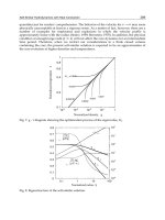
Fig. 41. Regulation of dwell angle according to load variation.
(a) steady-state. (b) load decreased. (c) load increased.
Fig. 42. Block diagram of PLL in SR drive.
2.2 Current control method
Control of the switched reluctance motor can be done in different ways. One of them is by
using current control method. The current control method is normally used to control the
torque efficiently. Voltage control has no limitation of the current as the current sensor is
avoided, which makes it applicable in low-cost systems. Due to the development of
233
Switched Reluctance Motor
Torque Control
234
microcontrollers, the different control loops have changed from analog to digital
implementation, which allows more advanced control features. However, problems are still
raised when designing high-performance current loop [miller,1990].
The main idea of current control method is timing and width of the voltage pulses. Two
methods are too used in the current control, one is voltage chopping control method, and
the other is hysteresis control method.
2.2.1 Voltage chopping control method
The voltage chopping control method compares a control signal ܸ
௧
(constant or slowly
varying in time) with a repetitive switching-frequency triangular waveform or Pulse Width
Modulation (PWM) in order to generate the switching signals. Controlling the switch duty
ratios in this way allowed the average dc voltage output to be controlled. In order to have a
fast built-up of the excitation current, high switching voltage is required. Fig. 43 shows an
asymmetric bridge converter for SR drive. The asymmetric bridge converter is very popular
for SR drives, consists of two power switches and two diodes per phase. This type of the SR
drive can support independent control of each phase and handle phase overlap. The
asymmetric converter has three modes, which are defined as magnetization mode,
freewheeling mode, and demagnetization mode as shown in Fig. 44.
a
i
b
i
c
i
Fig. 43. Asymmetric bridge converter for SR drive
(a) Magnetization (b) Freewheeling (c) Demagnetization
Fig. 44. Operation modes of asymmetric converter
From Fig. 44 (a) and (c), it is clear that amplitudes of the excitation and demagnetization
voltage are close to terminal voltage of the filter capacitor. The fixed DC-link voltage limits
the performance of the SR drive in the high speed application. On the other hand, the
234
Torque Controlo
Switched Reluctance Motor
235
voltage chopping method is useful for controlling the current at low speeds. This PWM
strategy works with a fixed chopping frequency. The chopping voltage method can be
separated into two modes: the hard chopping and the soft chopping method. In the hard
chopping method both phase transistors are driven by the same pulsed signal: the two
transistors are switched on and switched off at the same time. The power electronics board
is then easier to design and is relatively cheap as it handles only three pulsed signals. A
disadvantage of the hard chopping operation is that it increases the current ripple by a large
factor. The soft chopping strategy allows not only control of the current but a minimization
of the current ripple as well. In this soft chopping mode the low side transistor is left on
during the dwell angle and the high side transistor switches according to the pulsed signal.
In this case, the power electronics board has to handle six PWM signals [Liang,2006].
2.2.2 Hysteresis control method
Due to the hysteresis control, the current is flat, but if boost voltage is applied, the switching
is higher than in the conventional case. The voltage of the boost capacitor is higher in the
two capacitor parallel connected converter. The hysteresis control schemes for outgoing and
incoming phases are shown on the right side of Fig. 45.
Solid and dash lines denote the rising and falling rules, respectively. The y axis denotes
phase state and the x axis denotes torque error
ሺ
οܶ
ሻ
, which is defined as,
ο
ୣ୰୰
ൌ
୰ୣ
െ
ୣୱ୲
(35)
The threshold values of torque error are used to control state variation in hysteresis
controller. Compared to previous research, this method only has 3 threshold values (οܧ, 0
and -οܧ), which simplifies the control scheme. In order to reduce switching frequency, only
one switch opens or closes at a time. In region 1, the incoming phase must remain in state 1
to build up phase current, and outgoing phase state changes to maintain constant torque.
For example, assume that the starting point is (-1, 1), and the torque error is greater than 0.
The switching states for the two phases will change to (0, 1). At the next evaluation period,
the switching state will change to (1, 1) if torque error is more than οܧ and (-1, 1) if torque
error is less than -οܧ. So the combinatorial states of (-1, 1), (0, 0) and (1, 1) are selected by the
control scheme. The control schemes for region 2 and region 3 are shown in Fig. 45(b) and
(c), respectively.
3. Advanced torque control strategy
There are some various strategies of torque control: one method is direct torque control,
which uses the simple control scheme and the torque hysteresis controller to reduce the
torque ripple. Based on a simple algorithm, the short control period can be used to improve
control precision. The direct instantaneous torque control (DITC) and advanced DITC
(ADITC), torque sharing function (TSF) method are introduced in this section.
3.1 Direct Instantaneous Torque Control (DITC)
The asymmetric converter is very popular in SRM drive system. The operating modes of
asymmetric converter are shown in Fig. 46. The asymmetric converter has three states,
which are defined as state 1, state 0 and state -1 in DITC method, respectively.
235
Switched Reluctance Motor
Torque Control
236
(a) Region 1
(b) Region 2
(c) Region 3
Fig. 45. The hysteresis control schemes for outgoing and incoming phases
236
Torque Controlo
Switched Reluctance Motor
237
a
i
a
i
a
i
(a) state 1 (b) state 0 (c) state -1
Fig. 46. 3 states in the asymmetric converter
In order to reduce a torque ripple, DITC method is introduced. By the given hysteresis
control scheme, appropriate torque of each phase can be produced, and constant total
torque can be obtained. The phase inductance has been divided into 3 regions shown as Fig.
47. The regions depend on the structure geometry and load. The boundaries of 3 regions are
ߠ
ଵ
, ߠ
ଵ
, ߠ
ଶ
and ߠ
ଶ
in Fig. 47. ߠ
ଵ
and ߠ
ଶ
are turn-on angle in the incoming phase and
the next incoming phase, respectively, which depend on load and speed. The ߠ
ଵ
is a rotor
position which is initial overlap of stator and rotor. And ߠ
ଶ
is aligned position of inductance
in outgoing phase. Total length of these regions is 120 electrical degrees in 3 phases SRM.
Here, let outgoing phase is phase A and incoming phase is phase B in Fig. 47. When the first
region 3 is over, outgoing phase will be replaced by phase B in next 3 regions.
The DITC schemes of asymmetric converter are shown in Fig. 48. The combinatorial states of
outgoing and incoming phase are shown as a square mesh. x and y axis denote state of
outgoing and incoming phase, respectively. Each phase has 3 states, so the square mesh has
9 combinatorial states. However, only the black points are used in DITC scheme.
Z
Fig. 47. Three regions of phase inductance in DITC method
237
Switched Reluctance Motor
Torque Control
238
Outgoing
phase
(1,1)
1
(-1,1)
(0,1)
-1
Incoming phase
err
TE'!'
0
err
T'
err
TE''
0
err
T'!
(a) region 1 (b) region 2 (c) region 3
Fig. 48. DITC scheme of asymmetric converter
Control diagram of DITC SR motor drive is shown in Fig. 49. The torque estimation block is
generally implemented by 3-D lookup table according to the phase currents and rotor
position. And the digital torque hysteresis controller which carries out DITC scheme
generates the state signals for all activated machine phases according to torque error
between the reference torque and estimated torque. The state signal is converted as
switching signals by switching table block to control converter.
Through estimation of instantaneous torque and a simple hysteresis control, the average of
total torque can be kept in a bandwidth. And the major benefits of this control method are
its high robustness and fast toque response. The switching of power switches can be
reduced.
However, based on its typical hysteresis control strategy, switching frequency is not
constant. At the same time, the instantaneous torque cannot be controlled within a given
bandwidth of hysteresis controller. The torque ripple is limited by the controller sampling
time, so torque ripple will increase with speed increased.
est
T
*
ref
T
T
Fig. 49. Control diagram of DITC
Outgoing
phase
Incoming phase
err
TE'!'
0
err
T'
0
err
T'!
err
TE''
Outgoing
phase
Incoming phase
238
Torque Controlo
Switched Reluctance Motor
239
3.2 Advanced Direct Instantaneous Torque Control (ADITC)
The conventional DITC method uses a simple hysteresis switch rules, so only one phase
state is applied according to torque error at every sampling period. The toque variation with
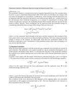
sampling time and speed under full dc-link voltage is shown in Fig. 50. In order to
guarantee the torque ripple within a range, it has two methods: one is that reduces sampling
time, which will increase the cost of hardware. Another is that control average voltage of
phase winding in sampling time. PWM method can be used.
Fig. 50. Torque variation with sampling time and speed
ADITC combines the conventional DITC and PWM method. The duty ratio of the phase
switch is regulated according to the torque error and simple control rules of DITC.
Therefore, the sampling time of control can be extended, which allows implementation on
low cost microcontrollers.
ADITC is improved from the conventional DITC, so the divided region of phase inductance
is similar to DITC method. The control scheme of ADITC is shown in Fig. 51, ܦ
௧ሺሻ
means
incoming phase, ܦ
௧ሺିଵሻ
means outgoing phase. X-axis denotes torque error, and y-axis
denotes switching state of ܦ
௧ሺሻ
and ܦ
௧ሺିଵሻ
.
err
T
H
T'
err
T
H
T'
err
T
H
T'
(a) Region 1 (b) Region 2 (c) Region
Fig. 51. ADITC scheme of asymmetric converter
Profit from the effect of PWM, the average voltage of phase winding can be adjusted from 0
to ܸ
ௗ
in one sampling time. And the hysteresis rule is removed from the control scheme.
Now, the current state can select the phase state between state 0 and 1 by duty ratio of
PWM.
0
500
1000
0
50
100
0
5
10
Speed [rpm]
Sampling time [
P
s]
'
Tm [%]
239
Switched Reluctance Motor
Torque Control
240
S
T
(1 )
tS
D
T
tS
D
T
S
T
(a) Incoming phase (b) outgoing phase
Fig. 52. Switching modes of incoming and outgoing phase
The duty ratio of switching modes is decided by the torque error as shown in Fig. 52, and
ܦ
௧
is expressed as follows:
୲
ൌ
ሺ
ୣ୰୰
ሻ
Ȁο
ୌ
(36)
Where, ܶ
is torque error, Ʀܶ
ு
is torque error bandwidth. The control block diagram of
ADITC is similar to Fig. 53. The hysteresis controller is replaced by Advanced DITC
controller, and the PWM generator is added.
est
T
*
ref
T
T
Fig. 53. Control diagram of ADITC
ADITC method can adjust average phase voltage to control variety of phase current in one
sampling time, which can extend the sampling time and obtain smaller torque ripple than
conventional DITC. However, PWM generator is added, and the switching frequency of
240
Torque Controlo
Switched Reluctance Motor
241
ADITC is double of DITC’s with uniform sampling time in the worst case. So the switching
loss and EMC noise are increased in ADITC method.
3.3 Torque sharing control
Another control method to produce continuous and constant torque is indirect torque
control, which uses the complicated algorithms or distribution function to distribute each
phase torque and obtain current command. And then, the current controller is used to
control phase torque by given current command. The linear, cosine and non linear logical
torque sharing function (TSF) are introduced.
Among them, the simple but powerful method is torque sharing function (TSF). The TSF
method uses the pre-measured non-linear torque characteristic, and simply divided torque
sharing curve is used for constant torque generation. Besides the direct torque control
method, another method is indirect torque control. TSF is simple but powerful and popular
method among the indirect torque control method. It simply divided by torque sharing
curve that is used for constant torque generation. And the phase torque can be assigned to
each phase current to control smoothing torque. But phase torque has relationship of square
current. So the current ripple should keep small enough to generate smooth torque. So the
frequency of current controller should be increased.
Fig. 54 shows the torque control block diagram with TSF method. The input torque
reference is divided into three-phase torque command according to rotor position. Torque
references of each phase are changed to current command signal in the “Torque-to-Current”
block according to rotor position. Since the output torque is determined by the inductance
slope and phase current, and the inductance slope is changed by rotor position, so the
reference currents of each phase is determined by the target torque and rotor position. The
switching rule generates an active switching signal of asymmetric converter according to
current error and hysteresis switching tables.
+
+
+
-
-
-
jG
yG
n
*
m
T
*
()mA
T
*
()mB
T
*
()mC
T
*
()mB
I
*
()mA
I
*
()mC
I
as
i
rm
T
()mA
S
()mC
S
()mB
S
Torque-to-Current
V
dc
bs
i
cs
i
Encoder
Switching
Rule
TSF
rm
T
rm
T
()mk
I
'
()mk
S
1
0
-1
Fig. 54. The torque control block diagram with TSF method
In the over-lap region of inductances, the two-phase currents generate the output torque
together. A simple torque sharing curves are studied for constant torque generation in the
commutation region such as linear and cosine function.
Fig. 55 shows the inductance profiles of three-phase SRM, cosine and linear TSF curves. As
shown in Fig. 55, region 2 denotes the one phase activation area. Region 1 and region 3 are
241
Switched Reluctance Motor
Torque Control
242
two phases activation area explained as the commutation region. In one phase activation
region, TSF is constant in every torque sharing functions. But TSF is different in the
commutation regions. The linear TSF has constant slope of torque in commutation region.
This method is simple, but it is very difficult to generate the linear torque slope in the
commutation region due to the non-linear inductance characteristics.
()Tk
f
(1)Tk
f
(1)Tk
f
rm
T
()on k
T
()off k
T
(1)on k
T
(1)off k
T
(2)on k
T
overlap
T
()Tk
f
(1)Tk
f
(1)Tk
f
rm
T
rm
T
()on k
T
()off k
T
(1)on k
T
(1)off k
T
(2)on k
T
Fig. 55. Phase inductances and cosine, and linear TSF curves
The cosine TSF uses the cosine function in commutation region as shown in Fig. 55. The
cosine function is relatively simple and it is similar to the non-linear inductance
characteristics. But the non-linear characteristic of SRM is very complex, so cosine torque
function can not be satisfied in the aspect of torque ripple and efficiency.
In the cosine TSF, the TSF of each phase in the commutation region are defined as follow
ሺ୩ሻ
ൌ
ଵ
ଶ
ͳെ൬
౨ౣ
ି
ሺౡሻ
౬౨ౢ౦
Ɏ൰൨ (37)
ሺ୩ିଵሻ
ൌͳെ
ሺ୩ሻ
(38)
ሺ୩ାଵሻ
ൌͲ (39)
And the linear TSF method, the TSF of each phase can be obtained as follow
ሺ୩ሻ
ൌ
౨ౣ
ି
ሺౡሻ
౬౨ౢ౦
(40)
242
Torque Controlo
Switched Reluctance Motor
243
ሺ୩ିଵሻ
ൌͳെ
ሺ୩ሻ
(41)
ሺ୩ାଵሻ
ൌͲ (42)
These two TSFs are very simple, but they can not consider nonlinear phenomena of the SRM
and torque dip is much serious according to rotor speed. For the high performance torque
control, a novel non-linear torque sharing function is suitable to use. In order to reduce
torque ripple and to improve efficiency in commutation region, the TSF uses a non-linear
current distribution technique at every rotor position. And the torque sharing function can
be easily obtained by the current coordinates of each rotor position. In the commutation
region, the total torque reference is divided by two-phase torque reference.
୫
כ
ൌ
୫ሺ୩ሻ
כ
୫ሺ୩ାଵሻ
כ
(43)
In the equation, the subscripts k+1 denotes the incoming phase and k denotes outgoing
phase. The actual torque can be obtained by inductance slope and phase current. So the
torque equation can be derived as follows.
୫
כ
=
୍
ౣሺౡሻ
כమ
ୟ
మ
+
୍
ౣሺౡశభሻ
כమ
ୠ
మ
(44)
where, ൌ
ඨ
ଶ
ப
ሺ
ౡ
ሻ
ப
ሺౣሻ
൘
, ൌ
ඨ
ଶ
ப
ሺ
ౡశభ
ሻ
ப
ሺౣሻ
൘
(45)
This equation is same as ellipse equation. In order to generate a constant torque reference,
current references of the outgoing and incoming phases is placed on the ellipse trajectory in
the commutation region. And the aspect of the ellipse and its trajectory is changed according
to rotor position, inductance shape and the reference torque. Since the TSFs uses a fixed
torque curve such as linear and cosine, the outgoing phase current should keep up the
reference. And the actual current should remain higher level around rotor aligned position.
Fig. 56 shows each phase current reference and actual phase torque for constant torque
production according to rotor position. As shown in Fig. 56, the actual torque profile has
non-linear characteristics around match position of rotor and stator position. So the current
reference of each phase for constant torque generation is changed according to the rotor
position and the amplitude of the torque reference. However, the actual phase current is
limited by the performance of a motor and a drive. And the actual torque can not be
satisfied the torque reference around the aligned position due to the non-linear torque
characteristics shown as Fig. 56. If the current of outgoing phase is increased as a limit value
of the motor, the actual torque is decreased afterܦ
position. And the actual torque of
incoming phase can not be satisfied at the start position of the commutation due to the same
reason. In order to generate the constant torque from ܣ
ܩ
ାଵ
, the outgoing and incoming
current reference should be properly selected so that the total torque of each phase is
remained as constant value ofܶ
כ
.
In order to reduce the commutation region, the outgoing phase current should be decreased
fast, and the incoming phase current should be increased fast with a constant torque
generation. At the starting point of commutation, the incoming phase current should be
increased from zero to ܣ
ାଵ
point, and the end of the commutation, the outgoing phase
current should be decreased from ܩ
point to zero as soon as possible shown in Fig. 56.
243
Switched Reluctance Motor
Torque Control
244
(1)on k
T
()off k
T
1
T
2
T
3
T
4
T
5
T
rm
T
*
(1)mk
I
*
()mk
I
()
mrm
T
T
*
m
T
Current
Limit
A
k
()mk
T
(1)mk
T
overlap
T
A
k+1
B
k
B
k+1
C
k
C
k+1
D
k
D
k+1
E
k
F
k
G
k
G
k+1
F
k+1
E
k+1
Fig. 56. Phase current and actual torque trajectory for constant torque production during
phase commutation
In order to reduce the torque ripple and increase the operating efficiency, a non-linear TSF is
based on minimum changing method. One phase current reference is fixed, and the other
phase current reference is changed to generate constant torque during commutation. Fig. 57
shows the basic principle of the non-linear TSF commutation method.
*
()mk
I
*
(1)mk
I
*
()mk
I
*
(1)mk
I
(a) In case of ܶ
൏ ܶ
כ
(b) In case of ܶ
ܶ
כ
Fig. 57. Basic principle of the commutation method based on minimum changing
In this method, the incoming phase current is changed to a remaining or an increasing
direction to produce the primary torque. And the outgoing phase current is changed to a
remaining or a decreasing direction to produce the auxiliary torque. In case of ܶ
൏ ܶ
כ
, the
outgoing phase current is fixed, and the incoming phase current is increased to reach the
constant torque line from ܲ
ଵ
to ܺ
ଵ
shown as Fig. 57(a). If the incoming phase current is
244
Torque Controlo
Switched Reluctance Motor
245
limited by the current limit and the actual torque is under the reference value, the auxiliary
torque is generated by the outgoing phase current from ܲ
ଶ
to ܺ
ଶ
shown as Fig. 57(a). In case
of ܶ
ܶ
כ
, the incoming phase current is fixed, and the outgoing phase current is decreased
to reach the constant torque line fromܳ
ଵ
to ܻ
ଵ
shown as Fig. 57(b), because the incoming
phase current is sufficient to generate the reference torque. If the outgoing phase current is
reached to zero, and the actual torque is over to reference value, the incoming phase current
is decreased from ܳ
ଶ
to ܻ
ଶ
shown as Fig. 57(b). This method is very simple, but the
switching number for torque control can be reduced due to the minimum number changing
of phase. As the other phase is fixed as the previous state, the torque ripple is dominated by
the one phase switching. Especially, the outgoing phase current is naturally decreased when
the incoming phase current is sufficient to produce the torque reference. The
demagnetization can be decreased fast, and the tail current which generates negative torque
can be suppressed.
Table 6 shows the logical TSF, and the Fig. 58 is the ideal current trajectory during
commutation region. In Fig. 58, the ellipse curves are current trajectory for constant torque
at each rotor position under commutation.
In case of
୫
൏
୫
כ
when In case of
୫
୫
כ
when
୫ሺ୩ାଵሻ
כ
୫
כ
െ
୫
ሺ
୩
ሻ
୫
ሺ
୩ାଵ
ሻ
כ
൏
୫ୟ୶
୫ሺ୩ሻ
כ
୫
כ
െ
୫ሺ୩ାଵሻ
୫ሺ୩ሻ
כ
Ͳ
୫
ሺ
୩ାଵ
ሻ
כ
*At current limit
୫ሺ୩ାଵሻ
כ
୫ୟ୶
0
୫ሺ୩ሻ
כ
൏Ͳ
୫ሺ୩ሻ
כ
୫
כ
െ
୫ሺ୩ାଵሻ
כ
୫ሺ୩ାଵሻ
כ
୫ሺ୩ାଵሻ
୫ሺ୩ሻ
כ
Ͳ
୫
כ
െ
୫
ሺ
୩
ሻ
୫ሺ୩ሻ
כ
൏Ͳ
Table 6. The logical TSF in commutation region.
*
(1)mk
I
*
()mk
I
()on k
T
1
T
2
T
3
T
4
T
5
T
(1)of f k
T
() 1 2 3 4 5 ( 1)on k off k
T
TTTTTT
Fig. 58. The ideal current trajectory at commutation region
245
Switched Reluctance Motor
Torque Control
246
*
m
T
m
T
*
(1)mk
T
(1)mk
T
*
(1)mk
I
(1)mk
I
(a) Linear TSF
*
m
T
m
T
*
(1)mk
T
(1)mk
T
*
(1)mk
I
(1)mk
I
(b) Cosine TSF
Fig. 59. Simulation result at 500 rpm with rated torque
246
Torque Controlo
Switched Reluctance Motor
247
*
m
T
m
T
*
(1)mk
T
(1)mk
T
*
(1)mk
I
(1)mk
I
(c) non-linear Logical TSF
Fig. 59. Simulation results at 500rpm with rated torque (continued)
In order to verify the non-linear TSF control scheme, computer simulations are executed and
compared with conventional methods. Matlab and simulink are used for simulation. Fig. 59
shows the simulation comparison results at 500[rpm] with rated torque reference. The
simulation results show the total reference torque, actual total torque, reference phase
torque, actual phase torque, reference phase current, actual phase current and phase
voltage, respectively. As shown in Fig. 59, torque ripple is linear TSF > cosine TSF > the
logical TSF.
Fig. 60 shows the actual current trajectory in the commutation region. In the conventional
case, the cross over of the outgoing and incoming phase is serious and two-phase current
are changed at each rotor position. But the cross over is very small and one-phase current is
changed at each rotor position in the logical TSF method.
()mk
I
(1)mk
I
()mk
I
(1)mk
I
()mk
I
(1)mk
I
(a) Linear TSF (b) Cosine TSF (c) logical TSF
Fig. 60. The current trajectory for constant torque production in commutation region
247
Switched Reluctance Motor
Torque Control
248
Fig. 61 shows the experimental setup. The main controller is designed by TMS320F2812
from TI(Texas Instruments) and phase current and voltage signals are feedback to 12bit
ADC embedded by DSP. The rotor position and speed is obtained by 512ppr optical
encoder. At every 1.6[ms], the rotor speed is calculated from captured encoder pulse by QEP
function of DSP.
Fig. 61. The experimental configuration
Fig. 62, 63 and 64 show the experimental results in case of linear TSF, cosine TSF and the
non-linear logical TSF at 500rpm, respectively. Torque ripple can be reduced in case of the
TSF method due to the minimum phase changing.
*
()mA
T
()mA
T
as
v
as
i
*
m
T
m
T
bs
i
as
i
(a) (b)
Fig. 62. Experimental results in linear TSF(at 500[rpm])
(a) Reference torque, actual torque, phase current and terminal voltage
(b) Total reference torque, actual torque and phase currents
Fig. 65 shows experimental results at 1200rpm. As speed increase, torque ripple is increased
due to the reduction of the commutation time. However, the control performance is much
improved in this case.
Fig. 66 shows efficiency of the logical control schemes. In the low speed range, the TSF
control scheme has about 5% higher efficiency than that of the conventional ones with low
torque ripple. In high speed range, the actual efficiency is similar to all other control method
due to the short commutation time. But the practical torque ripple can be reduced than other
two control schemes shown in simulation and experimental results.
248
Torque Controlo