Torque Control Part 14 pptx
Bạn đang xem bản rút gọn của tài liệu. Xem và tải ngay bản đầy đủ của tài liệu tại đây (779.6 KB, 20 trang )
Switched Reluctance Motor
249
*
()mA
T
()mA
T
as
v
as
i
*
m
T
m
T
bs
i
as
i
(a) (b)
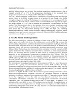
Fig. 63. Experimental results in cosine TSF(at 500[rpm])
(a) Reference, actual torque, phase current and terminal voltage
(b) Total reference torque, actual torque and phase currents
(a) (b)
Fig. 64. Experimental results in case of the non-linear logical TSF(at 500[rpm])
(a) Reference, actual torque, phase current and terminal voltage
(b) Total reference torque, actual torque and phase currents
4. Conclusion
The torque production in switched reluctance motor structures comes from the tendency of
the rotor poles to align with the excited stator poles. However, because SRM has doubly
salient poles and non-linear magnetic characteristics, the torque ripple is more severe than
these of other traditional motors. The torque ripple can be minimized through magnetic
circuit design or drive control. By controlling the torque of the SRM, low torque ripple,
noise reduction or even increasing of the efficiency can be achieved. There are many
different types of control methods. In this chapter, detailed characteristics of each control
method are introduced in order to give the advanced knowledge about torque control
method in SRM drive.
249
Switched Reluctance Motor
Torque Control
250
(a) Reference torque, total torque and phase currents in linear TSF
(b) Reference torque, total torque and phase currents in cosine TSF
(c) Reference torque, total torque and phase currents in non-linear logical TSF
Fig. 65. Experimental results at 1200rpm with rated torque
Fig. 66. Efficiency comparison
͖ͤ͡
͖ͥ͡
͖ͦ͡
͖ͧ͡
͖ͨ͡
͖ͩ͡
ͥ͡͡ ͧ͡͡ ͩ͡͡ ͢͡͡͡ ͣ͢͡͡ ͥ͢͡͡ ͧ͢͡͡ ͩ͢͡͡ ͣ͡͡͡
ΣΠΡΠΤΖΕ͑΅΄ͷ ʹΠΤ Κ ΟΖ͑΅΄ͷ ͽΚΟΖΒΣ͑΅΄
ͷ
Speed [rpm]
Efficiency
250
Torque Controlo
Switched Reluctance Motor
251
5. References
A. Chiba, K. Chida and T. Fukao, "Principles and Characteristics of a Reluctance Motor with
Windings of Magnetic Bearing," in Proc. PEC Tokyo, pp.919-926, 1990.
Bass, J. T., Ehsani, M. and Miller, T. J. E ; "Robust torque control of a switched reluctance
motor without a shaft position sensor," IEEE Transactions, Vol.IE-33, No.33, 1986,
212-216.
Bausch, H. and Rieke, B.; “Speed and torque control of thyristorfed reluctance motors."
Proceedings ICEM, Vienna Pt.I, 1978, 128.1-128.10. Also : "Performance of
thyristorfed electric car reluctance machines." Proceedings ICEM, Brussels E4/2.1-
2.10
Byrne, J. V. and Lacy, J.G.; "Characteristics of saturable stepper and reluctance motors." IEE
Conf. Publ. No.136,Small Electrical Machines, 1976, 93-96.
Corda, J. and Stephenson, J. M., "Speed control of switched reluctance motors," International
Conference on Electrical Machines, Budapest, 1982.
Cossar, C. and miller, T.J.E., "Electromagnetic testing of switched reluctance motors,"
International Conference on Electrical Machines, Manchester, September 15-17, 1992,
470-474.
Davis, R. M., "A Comparison of Switched Reluctance Rotor Structures," IEEE Trans. Indu.
Elec., Vol.35, No.4, pp.524-529, Nov. 1988.
D.H. Lee, J. Liang, Z.G. Lee, J.W. Ahn, "A Simple Nonlinear Logical Torque Sharing
Function for Low-Torque Ripple SR Drive", Industrial Electronics, IEEE
Transactions on, Vol. 56, Issue 8, pp.3021-3028, Aug. 2009.
D.H. Lee, J. Liang, T.H. Kim, J.W. Ahn, "Novel passive boost power converter for SR drive
with high demagnetization voltage", International Conference on Electrical
Machines and Systems, 2008, pp.3353-3357, 17-20 Oct. 2008.
D.H. Lee, T.H. Kim, J.W. Ahn, “ Pressure control of SR Driven Hydraulic Oil-pump Using
Data Based PID Controller”, Journal of Power Electronics Vol.9, September 2009.
D.S. Schramm, B.W. Williams, and T.C. Green; "Torque ripple reduction of switched
reluctance motors by phase current optimal profiling", in Proc. IEEE PESC' 92, Vol.
2, Toledo, Spain, pp.857-860, 1992 .
Harris, M. R. and Jahns, T. M., "A current-controlled switched reluctance drive for FHP
applications," Conference on Applied Motion Control, Minneapolis, June 10-12 , 1986.
Ilic-Spong, M., Miller, T. J. E., MacMinn, S. R. and Thorp, J. S., "Instantaneous torque control
of electric motor drives," IEEE Transactions, Vol.IA-22, 1987, 708-715.
J.W. Ahn, Se.G. Oh, J.W. Moon, Y.M. Hwang; "A three-phase switched reluctance motor
with two-phase excitation", Industry Applications, IEEE Transactions on, Vol.
35, Issue 5, pp.1067-1075, Sept Oct. 1999.
J.W. Ahn, S. G. Oh, and Y. M. Hwang, "A Novel Control Scheme for Low Cost SRM Drive, “
in Proc. IEEE/ISIE '95, July 1995, Athens, pp. 279-283.
J.W. Ahn, S.G. Oh, “ DSP Based High Efficiency SR Drive with Precise Speed Control”,
PESC ’99, june 27, Charleston, south Carolina.
J.W. Ahn, "Torque Control Strategy for High Performance SR Drive", Journal of Electrical
Engineering & Technology(JEET), Vol.3. No.4. 2008, pp.538-545.
J.W. Ahn , S. G. Oh, C. U. Kim, Y. M. Hwang, "Digital PLL Technique for Precise Speed
Control for SR Drive," in Proc. IEEE/PESC'99, Jun./Jul. 1999, Charleston, pp.815-819
251
Switched Reluctance Motor
Torque Control
252
J.M. Stephenson; J. Corda, "Computation of Torque and Current in Doubly-Salient
Reluctance Motors from Nonlinear Magnetization Data", Proceedings IEE, Vol. 126,
pp.393-396, May 1979.
J. N.Liang, Z. G. Lee, D. H. Lee, J. W. Ahn, " DITC of SRM Drive System Using 4-Level
Converter " , Proceedings of ICEMS 2006, Vol. 1, 21-23 Nov. 2006
J. N. Liang, S.H. Seok, D.H. Lee, J.W. Ahn, "Novel active boost power converter for SR drive"
International Conference on Electrical Machines and Systems, 2008, pp.3347-3352, 17-20
Oct. 2008.
Lawrenson, P.J.et al; "Variable-speed switched reluctance motors." Proceedings IEE. Vol.127,
Pt.B 253-265,1980.
M. Stiebler, G. Jie; "A low Voltage switched reluctance motor with experimentally optimized
control", Proceedings of ICEM '92, Vol. 2, pp. 532-536, Sep. 1992.
Miller, T. J. E., Bower, P. G., Becerra, R. and Ehsani, M., "Four- quadrant brushless reluctance
motor drive," IEE Conference on Power Electronics and Variable Speed Drives, London,
1988.
Pollock, C. and Willams, B. W.; "Power convertor circuit for switched reluctance motors
with the minimum number of switches," IEE Proceedings-B, Vol.137, 1990, No.6.
R. Krishnan; "Switched Reluctance Motor Drives: Modeling, Simulation, Analysis, Design, and
Applications", CRC Press, 2001
R. Orthmann, H.P. Schoner; "Turn-off angle control of switched reluctance motors for
optimum torque output", Proceedings of EPE '93, Vol. 6, pp.20-55, 1993.
Stephenson, J.M. and El-Khazendar, M.A., "Saturation in doubly salient reluctance motors,"
IEE Proceedings-B, Vol.136, No.1, 1989, 50-58.
T. Skvarenina; "The Power Electronics Handbook", CRC Press, 2002
T.J.E. Miller, M. McGilp, "Nonlinear theory of the switched reluctance motor for rapid
computer-aided design", IEE Proceedings B (Electric Power Applications), Vol. 137,
No. 6, pp.337-347, Nov. 1990.
Unnewehr, L. E. and Koch, W. H.; "An axial air-gap reluctance motor for variable-speed
applications." IEEE Transactions, 1974, PAS-93, 367-376.
Vukosavic, S. and Stefanovic, V. R., "SRM inverter topologiesΚa comparative evaluation,"
IEEE IAS Annual Meeting, Conf. Record, Seattle, WA, 1990.
Wallace, R. S. and Taylor, D. G., "Low torque ripple switched reluctance motors for direct-
drive robotics," IEEE Transactions on Robotics and Automation, Vol.7, No.6, 1991, 733-
742.
Wallace, R. S. and Taylor, D. G., "A balanced commutator for switched reluctance motors to
reduce torque ripple," IEEE Transactions on Power Electronics, October 1992.
252
Torque Controlo
9
Controller Design for Synchronous
Reluctance Motor Drive Systems
with Direct Torque Control
Tian-Hua Liu
Department of Electrical Engineering,
National Taiwan University of Science and Technolog
Taiwan
1. Introduction
A. Background
The synchronous reluctance motor (SynRM) has many advantages over other ac motors. For
example, its structure is simple and rugged. In addition, its rotor does not have any winding
or magnetic material. Prior to twenty years ago, the SynRM was regarded as inferior to
other types of ac motors due to its lower average torque and larger torque pulsation.
Recently, many researchers have proposed several methods to improve the performance of
the motor and drive system [1]-[3]. In fact, the SynRM has been shown to be suitable for ac
drive systems for several reasons. For example, it is not necessary to compute the slip of the
SynRM as it is with the induction motor. As a result, there is no parameter sensitivity
problem. In addition, it does not require any permanent magnetic material as the permanent
synchronous motor does.
The sensorless drive is becoming more and more popular for synchronous reluctance
motors. The major reason is that the sensorless drive can save space and reduce cost.
Generally speaking, there are two major methods to achieve a sensorless drive system:
vector control and direct torque control. Although most researchers focus on vector control
for a sensorless synchronous reluctance drive [4]-[12], direct torque control is simpler. By
using direct torque control, the plane of the voltage vectors is divided into six or twelve
sectors. Then, an optimal switching strategy is defined for each sector. The purpose of the
direct torque control is to restrict the torque error and the stator flux error within given
hysteresis bands. After executing hysteresis control, a switching pattern is selected to
generate the required torque and flux of the motor. A closed-loop drive system is thus
obtained.
Although many papers discuss the direct torque control of induction motors [13]-[15], only a
few papers study the direct torque control for synchronous reluctance motors. For example,
Consoli et al. proposed a sensorless torque control for synchronous reluctance motor drives
[16]. In this published paper, however, only a PI controller was used. As a result, the
transient responses and load disturbance responses were not satisfactory. To solve the
problem, in this chapter, an adaptive backstepping controller and a model-reference
adaptive controller are proposed for a SynRM direct torque control system. By using the
Torque Control
254
proposed controllers, the transient responses and load disturbance rejection capability are
obviously improved. In addition, the proposed system has excellent tracking ability. As to
the authors best knowledge, this is the first time that the adaptive backstepping controller
and model reference adaptive controller have been used in the direct torque control of
synchronous reluctance motor drives. Several experimental results validate the theoretical
analysis.
B. Literature Review
Several researchers have studied synchronous reluctance motors. These researchers use
different methods to improve the performance of the synchronous reluctance motor drive
system. The major categories include the following five methods:
1. Design and manufacture of the synchronous reluctance motor
The most effective way to improve the performance of the synchronous reluctance motor is
to design the structure of the motor, which includes the rotor configuration, the windings,
and the material. Miller et al. proposed a new configuration to design the rotor
configuration. By using the proposed method, a maximum
d
L /
q
L ratio to reach high power
factor, high torque, and low torque pulsations was achieved [17]. In addition, Vagati et al.
used the optimization technique to design a rotor of the synchronous reluctance motor. By
applying the finite element method, a high performance, low torque pulsation synchronous
reluctance motor has been designed [18]. Generally speaking, the design and manufacture of
the synchronous reluctance motor require a lot of experience and knowledge.
2. Development of Mathematical Model for the synchronous reluctance motor
The mathematical model description is required for analyzing the characteristics of the
motor and for designing controllers for the closed-loop drive system. Generally speaking,
the core loss and saturation effect are not included in the mathematical model. However,
recently, several researchers have considered the influence of the core loss and saturation.
For example, Uezato et al. derived a mathematical model for a synchronous reluctance
motor including stator iron loss [19]. Sturtzer et al. proposed a torque equation for
synchronous reluctance motors considering saturation effect [2]. Stumberger discussed a
parameter measuring method of linear synchronous reluctance motors by using current,
rotor position, flux linkages, and friction force [20]. Ichikawa et al. proposed a rotor
estimating technique using an on-line parameter identification method taking into account
magnetic saturation [5].
3. Controller Design
As we know, the controller design can effectively improve the transient responses, load
disturbance responses, and tracking responses for a closed-loop drive system. The PI
controller is a very popular controller, which is easy to design and implement.
Unfortunately, it is impossible to obtain fast transient responses and good load disturbance
responses by using a PI controller. To solve the difficulty, several advanced controllers have
been developed. For example, Chiang et al. proposed a sliding mode speed controller with a
grey prediction compensator to eliminate chattering and reduce steady-state error [21]. Lin
et al. used an adaptive recurrent fuzzy neural network controller for synchronous reluctance
motor drives [22]. Morimoto proposed a low resolution encoder to achieve a high
performance closed-loop drive system [7].
4. Rotor estimating technique
The sensorless synchronous reluctance drive system provides several advantages. For
example, sensorless drive systems do not require an encoder, which increases cost,
Controller Design for Synchronous Reluctance
Motor Drive Systems with Direct Torque Control
255
generates noise, and requires space. As a result, the sensorless drive systems can reduce
costs and improve reliability. Several researchers have studied the rotor estimating
technique to realize a sensorless drive. For example, Lin et al. used a current-slope to
estimate the rotor position and rotor speed [4]. Platt et al. implemented a sensorless vector
controller for a synchronous reluctance motor [9]. Kang et al. combined the flux-linkage
estimating method and the high-frequency injecting current method to achieve a sensorless
rotor position/speed drive system [23]. Ichikawa presented an extended EMF model and
initial position estimation for synchronous motors [10].
5. Switching strategy of the inverter for synchronous reluctance motor
Some researchers proposed the switching strategies of the inverter for synchronous
reluctance motors. For example, Shi and Toliyat proposed a vector control of a five-phase
synchronous reluctance motor with space vector pulse width modulation for minimum
switching losses [24].
Recently, many researchers have created new research topics for synchronous reluctance
motor drives. For example, Gao and Chau present the occurrence of Hopf bifurcation and
chaos in practical synchronous reluctance motor drive systems [25]. Bianchi, Bolognani, Bon,
and Pre propose a torque harmonic compensation method for a synchronous reluctance
motor [26]. Iqbal analyzes dynamic performance of a vector-controlled five-phase
synchronous reluctance motor drive by using an experimental investigation [27]. Morales
and Pacas design an encoderless predictive direct torque control for synchronous reluctance
machines at very low and zero speed [28]. Park, Kalev, and Hofmann propose a control
algorithm of high-speed solid-rotor synchronous reluctance motor/generator for flywheel-
based uniterruptible power supplies [29]. Liu, Lin, and Yang propose a nonlinear controller
for a synchronous reluctance drive with reduced switching frequency [30]. Ichikawa,
Tomita, Doki, and Okuma present sensorless control of synchronous reluctance motors
based on extended EMF models considering magnetic saturation with online parameter
identification [31].
2. The synchronous reluctance motor
In the section, the synchronous reluctance motor is described. The details are discussed as
follows.
2.1 Structure and characteristics
Synchronous reluctance motors have been used as a viable alternative to induction and
switched reluctance motors in medium-performance drive applications, such as: pumps,
high-efficiency fans, and light road vehicles. Recently, axially laminated rotor motors have
been developed to reach high power factor and high torque density. The synchronous
reluctance motor has many advantages. For example, the synchronous reluctance motor
does not have any rotor copper loss like the induction motor has. In addition, the
synchronous reluctance motor has a smaller torque pulsation as compared to the switched
reluctance motor.
2.2 Dynamic mathematical model
In synchronous d-q reference frame, the voltage equations of the synchronous reluctance
motor can be described as
Torque Control
256
q
ss
q
s
q
srds
vrip
λ
ωλ
=
++ (1)
ds s ds ds r
q
s
vrip
λ
ωλ
=
+− (2)
where
q
s
v and
ds
v are the q-axis and the d-axis voltages,
s
r is the stator resistance,
q
s
i is the
q-axis equivalent current,
ds
i is the d-axis equivalent current, p is the differential operator,
q
s
λ
and
ds
λ
are the q-axis and d-axis flux linkages, and
r
ω
is the motor speed. The flux
linkage equations are
()
q
slsm
s
LL i
λ
=
+ (3)
()
ds ls md ds
LL i
λ
=+
(4)
where
ls
L is the leakage inductance, and
m
q
L
and
md
L are the q- axis and d-axis mutual
inductances. The electro-magnetic torque can be expressed as
e
T =
3
2
0
2
P
(
md m
q
LL
−
)
ds
i
q
s
i (5)
where
e
T is the electro-magnetic torque of the motor, and
0
P is the number of poles of the
motor. The rotor speed and position of the motor can be expressed as
p
rm
ω
=
1
J
(
e
T -
l
T - B
rm
ω
) (6)
and
p
rm
θ
=
rm
ω
(7)
where
J
is the inertia constant of the motor and load,
l
T is the external load torque, B is the
viscous frictional coefficient of the motor and load,
rm
θ
is the mechanical rotor position, and
rm
ω
is the mechanical rotor speed. The electrical rotor speed and position are
0
2
rrm
P
ω
ω
=
(8)
0
2
rrm
P
θ
θ
=
(9)
where
r
ω
is the electrical rotor speed, and
r
θ
is the electrical rotor position of the motor.
2.3 Steady-state analysis
When the synchronous reluctance motor is operated in the steady-state condition, the d-q
axis currents,
d
i and
q
i
, become constant values. We can then assume
q
e
q
s
xL
ω
=
and
d
x =
e
ω
ds
L , and derive the steady-state d-q axis voltages as follows:
dsd
vrixi
=
−
(10)
Controller Design for Synchronous Reluctance
Motor Drive Systems with Direct Torque Control
257
q
s
q
dd
vrixi
=
+
(11)
The stator voltage can be expressed as a vector
s
V and shown as follows
s
q
d
Vv
j
v
=
− (12)
Now, from equations (10) and (11), we can solve the d-axis current and q-axis current as
2
sd
d
sd
q
rv x v
i
rxx
+
=
+
(13)
and
2
s
q
dd
q
sd
q
rv x v
i
rxx
−
=
+
(14)
By substituting equations (13)-(14) into (5), we can obtain the steady-state torque equation as
222
22
31
[( ) ( ) ( ) ]
22
()
dq
es
sdd s d
q
d
q
e
sdq
xx
P
T rxv rxv r xx vv
rxx
ω
−
=−+−
+
(15)
According to (15), when the stator resistance
s
r is very small and can be neglected, the
torque equation (15) can be simplified as
2
31
sin(2 )
22 2
dq
es
edq
xx
P
TV
xx
δ
ω
−
=
(16)
The output power is
2
()
2
3
sin(2 )
22
e
e
dq
s
dq
PT
P
xx
V
xx
ω
δ
=
−
=
(17)
where P is the output power, and
δ
is the load angle.
3. Direct torque control
3.1 Basic principle
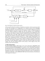
Fig. 1 shows the block diagram of the direct torque control system. The system includes two
major loops: the torque-control loop and the flux-control loop. As you can observe, the flux
and torque are directly controlled individually. In addition, the current-control loop is not
required here. The basic principle of the direct torque control is to bound the torque error
and the flux error in hysteresis bands by properly choosing the switching states of the
inverter. To achieve this goal, the plan of the voltage vector is divided into six operating
Torque Control
258
sectors and a suitable switching state is associated with each sector. As a result, when the
voltage vector rotates, the switching state can be automatically changed. For practical
implementation, the switching procedure is determined by a state selector based on pre-
calculated look up tables. The actual stator flux position is obtained by sensing the stator
voltages and currents of the motor. Then, the operating sector is selected. The resolution of
the sector is 60 degrees for every sector. Although the direct torque is very simple, it shows
good dynamic performance in torque regulation and flux regulation. In fact, the two loops
on torque and flux can compensate the imperfect field orientation caused by the parameter
variations. The disadvantage of the direct torque control is the high frequency ripples of the
torque and flux, which may deteriorate the performance of the drive system. In addition, an
advanced controller is not easy to apply due to the large torque pulsation of the motor.
In Fig.1, the estimating torque and flux can be obtained by measuring the a-phase and the b-
phase voltages and currents. Next, the speed command is compared with the estimating
speed to compute the speed error. Then, the speed error is processed by the speed controller
to obtain the torque command. On the other hand, the flux command is compared to the
estimated flux. Finally, the errors
e
T
Δ
and
s
λ
Δ
go through the hysteresis controllers and the
switching table to generate the required switching states. The synchronous reluctance motor
rotates and a closed-loop drive system is thus achieved. Due to the limitation of the scope of
this paper, the details are not discussed here.
Fig. 1. The block diagram of the direct torque control system
3.2 Controller design
The SynRM is easily saturated due to its lack of permanent magnet material. As a result, it
has nonlinear characteristics under a heavy load. To solve the problem, adaptive control
algorithms are required. In this paper, two different adaptive controllers are proposed.
Controller Design for Synchronous Reluctance
Motor Drive Systems with Direct Torque Control
259
A. Adaptive Backstepping Controller
From equation (6), it is not difficult to derive
[]
12 3
1
reLmr
m
eL r
d
TT B
dt J
AT AT A
ωω
ω
=−−
=++
(18)
and
1
1
m
A
J
= (19)
2
1
m
A
J
=− (20)
3
m
m
B
A
J
=− (21)
Where
1
A ,
2
A ,
3
A are constant parameters which are related to the motor parameters. In
the real world, unfortunately, the parameters of the SynRM can not be precisely measured
and are varied by saturated effect or temperature. As a result, a controller designer should
consider the problem. In this paper, we proposed two control methods. The first one is an
adaptive backstepping controller. In this method, we consider the parameter variations and
external load together. Then
r
d
dt
ω
=
13er
AT A
ω
+
2
(
L
A
T+ +
12e
A
TA
Δ
+Δ
L
T +
3 r
A
ω
Δ ) =
13er
AT A
ω
+ +d (22)
and
d=
2
(
L
A
T
+
12e
A
TA
Δ
+Δ
L
T
+
3 rm
A
ω
Δ
) (23)
where
1
AΔ ,
2
AΔ ,
3
A
Δ
are the variations of the parameters, and d is the uncertainty
including the effects of the parameter variations and the external load.
Define the speed error
2
e
as
*
2 rm rm
e
ω
ω
=−
(24)
Taking the derivation of both sides, it is easy to obtain
*
2rm
rm
e
ω
ω
=−
(25)
In this paper, we select a Lyapunov function as
()
22
2
2
2
2
111
V
22
111
ˆ
22
ed
edd
γ
γ
=+
=+ −
(26)
Torque Control
260
Taking the derivation of equation (26), it is easy to obtain
()
22
22
22
1
V
1
ˆ
1
ˆ
ee dd
ee dd d
ee dd
γ
γ
γ
=+
=
+−
=−
(27)
By substituting (25) into (27) and doing some arrangement, we can obtain
(
)
()
*
213
*
213
1
ˆ
VAA
1
ˆˆ
AA
rm e rm
rm e rm
eT ddd
eT dddd
ωω
γ
ωω
γ
=−−−−
=−−−−−
(28)
Assume the torque can satisfy the following equation
(
)
*
32
1
1
ˆ
AM
A
ermrm
Tde
ωω
=−−+
(29)
Substituting (29) into (28), we can obtain
2
22
1
ˆ
VMede dd
γ
=− − −
(30)
From equation (30), it is possible to cancel the last two terms by selecting the following
adaptive law
2
ˆ
de
γ
=−
(31)
In equation (31), the convergence rate of the
d
∧
is related to the parameter
γ
. By submitting
(31) into (30), we can obtain
2
2
VM 0e
=
−≤
(32)
From equation (32), we can conclude that the system is stable; however, we are required to
use Barbalet Lemma to show the system is asymptotical stable [32]-[34].
By integrating equation (32), we can obtain
0
VV()V(0) < d
τ
∞
=
∞− ∞
∫
(33)
From equation (33), the integrating of parameter
2
2
e of the equation (32) is less than infinite.
Then,
22
() L Let
∞
∈∩, and
2
()et
is bounded. According to Barbalet Lemma, we can
conclude [32]-[34]
2
lim ( ) 0
t
et
→∞
=
(34)
Controller Design for Synchronous Reluctance
Motor Drive Systems with Direct Torque Control
261
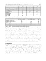
The block diagram of the proposed adaptive backstepping control system is shown in Fig. 2,
which is obtained from equations (29) and (31).
Fig. 2. The adaptive backstepping controller.
B. Model-Reference Adaptive Controller
Generally speaking, after the torque is applied, the speed of the motor incurs a delay of
several micro seconds. As a result, the transfer function between the speed and the torque of
a motor can be expressed as:
-
1
e
s
rm m
m
e
m
J
B
T
s
J
τ
ω
=
⎛⎞
+
⎜⎟
⎝⎠
(35)
Where
τ
is the delay time of the speed response. In addition, the last term of equation (35)
can be described as
1
1
s
e
s
τ
τ
−
≅
+
1/
1/s
τ
τ
≅
+
(36)
Substituting (36) into (35), one can obtain
0
2
10
1
1
1
()
()
rm m
m
e
m
Jb
B
T
sasa
s
s
J
ω
τ
τ
==
+
+
+
+
(37)
where
1
1
()
m
m
B
a
J
τ
=+ (38a)
Torque Control
262
0
m
m
B
a
J
τ
= (38b)
0
1
m
b
J
τ
= (38c)
Equation (37) can be described as a state-space representation:
11
20120
01 0
+
xx
u
xaaxb
⎡
⎤⎡ ⎤⎡⎤⎡⎤
=
⎢
⎥⎢ ⎥⎢⎥⎢⎥
⎣
⎦⎣ ⎦⎣⎦⎣⎦
(39a)
[]
1
2
1 0
x
y
x
⎡
⎤
=
⎢
⎥
⎣
⎦
(39b)
Where
1 rm
p
xy
ω
==
,
2 rm
x
ω
=
, and
e
uT
=
. Next, the equations (39a) and (39b) can be
rewritten as :
+
pppp
XAXBu=
(40a)
and
T
ppp
y
CX= (40b)
where
1
2
p
x
X
x
⎡
⎤
=
⎢
⎥
⎣
⎦
(41a)
01
01
p
A
aa
⎡
⎤
=
⎢
⎥
−−
⎣
⎦
(41b)
0
0
p
B
b
⎡
⎤
=
⎢
⎥
⎣
⎦
(41c)
[
]
10
T
p
C = (41d)
After that, we define two state variables
1
w and
2
w as:
11
-whwu
=
+
(42)
and
22
-
p
whwy
=
+
(43)
The control input
u can be described as
Controller Design for Synchronous Reluctance
Motor Drive Systems with Direct Torque Control
263
11 22 0
p
uKrQw Qw Q
y
=
+++ (44)
=
T
θ
φ
where
[
]
120
T
KQ Q Q
θ
=
and
12
T
p
rw w y
φ
⎡
⎤
=
⎣
⎦
where
γ
is the reference command. Combining (40a),(42), and (43), we can obtain a new
dynamic equation as
11
22
00
0- 0 1
0
0-
pp pp
T
p
XA XB
whwu
ww
Ch
⎡⎤
⎡⎤
⎡
⎤⎡⎤
⎢⎥
⎢⎥
⎢
⎥⎢⎥
=+
⎢⎥
⎢⎥
⎢
⎥⎢⎥
⎢⎥
⎢⎥
⎢
⎥⎢⎥
⎢⎥
⎢
⎥⎣ ⎦ ⎣ ⎦
⎣⎦
⎣⎦
(45)
Substituting (44) into (45), we can obtain
012
10 121
22
-
0
0-
T
pp p p p
ppp
T
p
T
p
A BQC BQ BQ
XXBK
wQChQQwKr
ww
Ch
⎡⎤
+
⎡⎤
⎡
⎤⎡ ⎤
⎢⎥
⎢⎥
⎢
⎥⎢ ⎥
⎢⎥
=++
⎢⎥
⎢
⎥⎢ ⎥
⎢⎥
⎢⎥
⎢
⎥⎢ ⎥
⎢⎥
⎢⎥
⎣
⎦⎣ ⎦
⎣⎦
⎣⎦
(46)
Define
*
KKK=−
,
*
111
QQQ=−
,
*
222
QQQ=−
,
*
000
QQQ=−
Then, equation (46) can be rearranged as
****
012
****
10 12
2
-1
00
0-
T
pp p p p p
pp
TT
p
T
p
ABQC BQ BQ BK
XB
wQChQQKr
w
Ch
θ
φ
⎡⎤⎡⎤
+
⎡⎤
⎡⎤
⎢⎥⎢⎥
⎢⎥
⎢⎥
⎢⎥⎢⎥
=+++
⎢⎥
⎢⎥
⎢⎥⎢⎥
⎢⎥
⎢⎥
⎢⎥⎢⎥
⎢⎥
⎣⎦
⎣⎦
⎣⎦⎣⎦
(47)
Where
120
T
KQ Q Q
θ
⎡⎤
=
⎣⎦
is the parameter errors. It is possible to rearrange equation
(47) as a simplified form
*
*
0
p
T
cmc m
BK
XAX KrB
θ
φ
⎡⎤
⎢⎥
⎢⎥
=+ +
⎢⎥
⎢⎥
⎣⎦
(48)
and
T
cmc
YCX= (49)
Torque Control
264
where
***
012
***
1012
2
, - ,
0-
10, 00.
T
pp p p p
p
T
cm p
T
p
TTT
mp mp
ABQC BQ BQ
X
XwA QC hQQ
w
Ch
BB CC
⎡
⎤
+
⎡⎤
⎢
⎥
⎢⎥
⎢
⎥
== +
⎢⎥
⎢
⎥
⎢⎥
⎢
⎥
⎣⎦
⎣
⎦
⎡⎤
⎡⎤
==
⎣⎦
⎣⎦
After that, the referencing model of the closed-loop system can be described as :
*
mmmm
XAXBKr=+
(50)
and
T
mmm
YCX= (51)
where
***
12
T
mp
XXww
⎡⎤
=
⎣⎦
is the vector of the state variables, and
m
Y is the output of the
referencing model. Now, we define the derivation of the state variable error and the output
error as:
cm
eX X=−
(52)
and
1 cm
eYY
=
− (53)
Substituting (50)-(51) into (52) and (53), one can obtain
T
mm
eAeB
θ
φ
=+
(54a)
and
1
T
m
eCe= (54b)
By letting
*
mm
BBK= , it is not difficult to rearrange (54a) as
*
1
T
mm
eAeB
K
θ
φ
=+
(55a)
Combining (54b) and (55a), one can obtain
()
-1
1
*
1
TT
mmm
eCsIAB
K
θ
φ
=−
(56)
It is essential that the degree of the referencing model equal the uncontrolled plant. As a
result, equation (55a) has to be revised as [12]:
Controller Design for Synchronous Reluctance
Motor Drive Systems with Direct Torque Control
265
1
*
1
T
mm
eAeB
K
θ
φ
=+
(57a)
where
()
1mm
s
BBL= ,
()
-1
s
L
φ
φ
= ,
()
; 0
s
LsFF
=
+>
’
After that, we can obtain
()
-1
11
*
1
TT
mmm
eCsIAB
K
θ
φ
=−
(58)
Now, selecting a Lyapunov function as
-1
*
111
V
22
TT
m
ePe
K
θθ
=+Γ
(59)
where
m
P is a symmetry positive real matrix, and
Γ
is a positive real vector.
The matrix
m
P satisfies the following two equations:
Q
T
mm m m
AP PA
+
=− (60)
and
1
T
mm m
PB C= (61)
where Q is a symmetry positive real matrix . Taking the derivation of equation (59) and
substituting (60), (61) into the derivation equation, we can obtain
-1
1
**
-1
1
**
-1 1 1
VQ
2
-1 1 1
Q
2
TT TT
mm
TTT
eeePB
KK
eee
KK
θφ θ θ
θφ θ θ
=+ +Γ
=+ +Γ
(62)
It is possible to select the adaptive law as
1
*
1
-sgn( )
e
K
θ
φ
=Γ
(63)
where
*
**
1
sgn( )
K
KK
= , substituting (63) into (62), we can obtain :
-1
VQ0
2
T
ee
=
≤
(64)
Next, by using Barbalet Lemma, we can obtain that the system is asymmetrical and
lim
t→∞
1
()et=0 (65)
Finally, we can obtain
Torque Control
266
() () ()
-1
TT
p
ss s
TT TTT
uL L L
F
θφθφ
θ
φθφ θφθφθφ
==
=++ =+
(66)
The block diagram of the model-reference control system is shown in Fig. 3, which includes
referencing model, adaptive controller, and adaptive law.
2
b
s
as b
+
+
TT
p
u
θ
φθφ
=+
1
w
1
s
h
+
1
s
h
+
1
s
h
+
1
s
h
+
2
w
12
T
p
rww y
φ
⎡
⎤
=
⎣
⎦
p
y
m
y
1
e
+
−
r
φ
p
u
1
s
φ
T
θ
T
θ
1
s
F+
2
1
1
()
m
mm
mm
J
B
B
ss
JJ
τ
τ
τ
+++
1
*
1
sgn( )
T
e
K
θ
φ
=− Γ
Fig. 3. The block diagram of the model reference adaptive controller.
4. Implementation
The implemented system is shown in Fig. 4. The system includes two major parts: the
hardware circuits and the software programs. The hardware circuits include: the
synchronous reluctance motor, the driver and inverter, the current and voltage sensors, and
the A/D converters. The software programs consist of the torque estimator, the flux
estimator, the speed estimator, the adaptive speed controller, and the direct torque control
algorithm. As you can observe, the most important jobs are executed by the digital signal
processor; as a result, the hardware is quite simple. The rotor position can be obtained by
stator flux, which is computed from the stator voltages and the stator currents. The digital
signal processor outputs triggering signals every 50
s
μ
; as a result, the switching frequency
of the inverter is 20 kHz. In addition, the sampling interval of the speed control loop is 1 ms
Controller Design for Synchronous Reluctance
Motor Drive Systems with Direct Torque Control
267
although the adaptive controllers are quite complicated. The whole drive system, therefore,
is a multi-rate fully digital control system.
DSP
Driver
and
Inverter
SynRM
Voltage
and
Current
Sensors
a
v
b
v
b
i
a
i
'
11
, TT
'
22
, TT
'
33
, TT
Fig. 4. The implemented system.
A. Hardware Circuits
The hardware circuits of the synchronous reluctance drive system includes the major parts.
The details are discussed as follows.
a.
The delay circuit of the IGBT triggering signals.
Fig. 5 shows the proposed delay circuit of the IGBT triggering signals. The delay circuit is
designed to avoid the overlapping period of the turn-on interval of the upper IGBT and the
lower IGBT for the inverter. Then, the inverter can avoid a short circuit. In this paper, the
delay time of the delay circuit is set as 2
s
μ
. To achieve the goal, two integrated circuit chips
are used: 74LS174 and 74LS193. The basic idea is described as follows. First, the digital
signal processor sends a clock signal to 74LS193. The time period of the clock is 62.5
s
μ
. The
74LS193 executes the dividing frequency function and finally generates a clock signal with a
0.5
s
μ
period. After that, the 74LS193 sends it into the CLK pin of 74LS174. The 74LS174
provides 6 series D-type flip-flop to generate a 3
s
μ
delay. Finally, an AND gate is used to
make a 3
s
μ
for a rising-edge triggering signal but not a falling-edge triggering signal.
b.
The driver of the IGBTs
The power switch modules used in the paper are IGBT modules, type 2MBI50-120. Each
module includes two IGBTs and two power diodes. The driver of the IGBT is type EX-B840,
made by Fuji company. The detailed circuit of the driver for an IGBT is shown in Fig. 6. In
Fig. 6, the EX-B840, which is a driver, uses photo-couple to convert the control signal into a
Torque Control
268
DSP trigger
U1
74LS174
3
4
6
11
13
9
1
2
5
10
12
7
1415
1D
2D
3D
4D
5D
CLK
CLR
1Q
2Q
4Q
5Q
3Q
6D6Q
H1
Driver
U7
74LS193
5
4
14
11
15
1
10
9
3
2
6
7
13
12
UP
DOWN
CLR
LOAD
A
B
C
D
QA
QB
QC
QD
BO
CO
U8A
7408
1
2
3
DSP H1
+5V
Fig. 5. The delay circuit of the IGBT triggering signals.
triggering signal for an IGBT. In addition, the EX-B840 provides the isolation and over-
current protection as well.
When the control signal is “High”, the photo transistor is turned on. Then, the photo diode
is conducted. A 15V can across the gate and emitter of the IGBT to turn on the IGBT. On the
other hand, when the control signal is “Low”, the photo transistor is turned off. As a result,
the photo diode is cut off. A -5V can across the gate and emitter of the IGBT to make IGBT
turn off immediately.
The protection of the IGBT is included in Fig. 6. When the IGBT has over-current, the
voltage across the collector and emitter of the IGBT is obviously dropped. After the 6-pin of
EX-B840 detects the dropped voltage, the 5-pin of the EX-B840 sends a “Low” voltage to the
photo diode. After that, the photo diode is opened, and a -5V across the gate and emitter of
the IGBT is sent to turn off the IGBT.
c.
The snubber circuit
The snubber circuit is used to absorb spike voltages when the IGBT is turned off. As we
know, the synchronous reluctance motor is a kind of inductive load. In Fig. 7, when the
upper leg IGBT T is turned off, the low leg IGBT
'
T cannot be turned on immediately due to
the required dead-time, which can avoid short circuits. A new current path to keep the
current continuous flow is required. The new current path includes the fast diode D and the
snubber capacitor
s
C
. So, the current can flow through the fast diode D and the
capacitor
S
C
, and then stores its energy into the capacitor
S
C
. On the other hand, when the
IGBT is turned on in next time interval, the stored energy in the capacitor
S
C
can flow
through the resistance
s
R
and the IGBT
T
. Finally, the energy dissipates in the resistance
s
R
. By suitably selecting the parameter
s
C
and
s
R
, a snubber circuit with satisfactory
performance can be obtained.
d.
The current detecting circuit
The current detecting circuit is used to measure the stator current of the synchronous
reluctance motor, and can be shown in Fig. 8. The Hall current sensor, typed LP-100, is used
to sense the stator current of the motor and to provide the isolation between the power stage