báo cáo hóa học:" Hip abductor moment arm - a mathematical analysis for proximal femoral replacement" pdf
Bạn đang xem bản rút gọn của tài liệu. Xem và tải ngay bản đầy đủ của tài liệu tại đây (1.65 MB, 10 trang )
RESEARC H ARTIC L E Open Access
Hip abductor moment arm - a mathematical
analysis for proximal femoral replacement
Eric R Henderson
1*†
, German A Marulanda
1†
, David Cheong
2†
, H Thomas Temple
3†
, G Douglas Letson
2†
Abstract
Background: Patients undergoing proximal femoral replacement for tumor resection often have compromised hip
abductor muscles resulting in a Trendelenberg limp and hip instability. Commercially available proximal femoral
prostheses offer several designs wi th varying sites of attachment for the abductor muscles, however, no analyses of
these configurations have been performed to determine which design provides the longest moment arm for the
hip ab ductor muscles during normal function.
Methods: This study analyzed hip abductor moment arm through hip adduction and abduction with a
trigonometric mathematical model to evaluate the effects of alterations in anatomy and proximal femoral
prosthesis design. Prosthesis dimensions were taken from technical schematics that were obtained from the
prosthesis manufacturers. Manufacturers who contributed schematics for this investigation were Stryker
Orthopaedics and Biomet.
Results: Superior and lateral displacement of the greater trochanter increased the hip abductor mechanical
advantage for single-leg stance and adduction and preserved moment arm in the setting of Trendelenberg gait.
Hip joint medialization resulted in less variance of the abductor moment arm through coronal motion. The Stryker
GMRS endoprosthesis provided the longest moment arm in single-leg stance.
Conclusions: Hip abductor moment arm varies substantially throughout the hip’s range of motion in the coronal
plane. Selection of a proximal femur endoprosthesis with an abductor muscle insertion that is located superiorly
and laterally will optimize hip abductor moment arm in single-leg stance compared to one located inferiorly or
medially.
Background
Proximal femoral reconstruction is a challenging proce-
dure that is commonly indicated in orthopaedic oncol-
ogy, complex hip revision surgery, and trauma [1,2]. The
replacement of the proximal femur irreversibly affects
the normal anatomy and biomechanics of the hip joint.
A Trendelenberg gait is the most common reported com-
plication of proximal femoral replacement [1-7]. In addi-
tion, falling is a common source of postoperative
morbidity and has been linked to postural instability and
muscle weakness in the single leg stance [8,9]. Lower
extremity strength and standing balan ce have also been
shown to be predictive of disability [10]. Johnston et al
reported that there are three hip factors that determine
the occurrence of a limp [11]. The first factor is the
moment (torque) that a given muscle must generate. The
second factor is the length of the moment arm of that
muscle and the third is the strength of the given muscle.
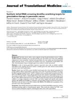
The moment arm of a given muscle (effective lever arm)
is the length of a straight line originating at the joint cen-
ter (femoral head), and terminating at a point 90° to the
muscle’s line of action (Figure 1).
The greater trochanter in the normal femur serves as
the insertion point for the hip abductor muscles, gluteus
medius and gluteus minimus. Normal function of these
muscles is required for single-leg stance an d ambulation
[11-15]. Altering the site of the insertion of the abductor
muscles, as is seen with proximal femoral replacement,
significantly affects hip biomechanics [11-15].
Muscle moment arm is usually discussed as a static
quantity. Motion at the hip joint, however, requires the
* Correspondence:
† Contributed equally
1
Department of Orthopaedics and Sports Medicine, 13220 Laurel Drive,
University of South Florida, Tampa, Florida, 33612, USA
Full list of author information is available at the end of the article
Henderson et al. Journal of Orthopaedic Surgery and Research 2011, 6:6
/>© 2011 Henderson et al; licensee BioMed Central Ltd. This is an Open Access article distributed under the terms of the Creative
Commons Attribution License ( which permits unrestricted use, distribution, and
reproduction in any medium, provided the original work is properly cited.
fem ur to move relative to the pelvis, resulting in altera-
tions in abductor moment arm with gait [13]. Evaluating
hip abductor moment arm as the hip travels through its
coronal range of motion has not been performed pre-
viously. The purpose of this study was to analyze the
abductor moment arm characteristics through hip
adduction and abduction. In addition, the authors will
provide an objective evaluation of the clinical and
mechanical advantages afforded by specific alterations in
patient anatomy and commercially-available proximal
femoral endoprostheses.
Methods
A mathematical model of abductor moment arm,
defined by anatomical coordinates of the origins and
insertions of the gluteus medius and minimus and the
femoral head center, was derived using anatomical mea-
surements published previously (Figure 1) [11,13,16].
The straight line method of approximating the path of
muscle pull was used for this study s ince the broad
attachments of the gluteus medius and gluteus minimus
do not facilitate definition of the transverse sections
required for the centroid line model [11,16,17].
Derivation of the mathematical model began with the
equation for moment arm (Equation 1, see Appendix).
Moment arm w as calculated by def ining the lever arm
(r) in terms of the femoral head and abductor muscle
insertions (Equation 2), and defining the angle of pull
(θ) in terms of the femoral head, muscle origins, and
insertions (Equation 3). The moment arm could there-
fore be calculated and plotted for all values of a muscle’s
origin, insertion, and joint center (Equation 4).
The moment arm of the normal femur was calculated
and plotted from 30° of adduction through 45° of abduc-
tion using mathematics software (Maplesoft, Ontario,
Canada), which was then employed for all further ana-
lyses [16]. Modifications of the greater trochanter that
were analyzed and plotted included several modes of
displacement: two centimeters (cm) of lateral, medial,
superior, inferior, or supero-lateral displacement. Modi-
fications of the moment arm equation were required for
this analysis (Equations 5 and 6).
Figure 1 Coronal view of hip demonstrating hip abductor moment arm, (red line). Coronal view of hip demonstrating hip a bductor
moment arm, defined as the length of a line originating at the joint center (red) which forms a 90˚ angle with the line of action (blue).
Henderson et al. Journal of Orthopaedic Surgery and Research 2011, 6:6
/>Page 2 of 10
Thesecondanalysiscomparedabductormomentarm
through 30° of adduction and 45° of abduction for three
commercially-available proximal f emur prostheses and
the normal femur. These prostheses were the Biomet
7 cm Letson Proximal Component, Biomet 7 cm Finn
Proximal Component, (Biomet Orthopedics, Warsaw,
Indiana, USA) and the Stryker Global Modular Replace-
ment System with greater trochanter (GMRS, Stryker
Orthopedics, Mahwah, New Jersey, USA). The design
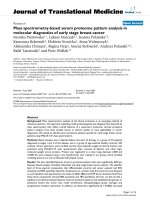
data for the prostheses were obt ained from schem atics
provided by the manufacturers (Figure 2).
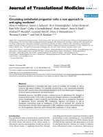
Abductor moment arm was also analyzed in the setting
of abductor muscle weakness and a Trendelenberg gait,
simulated as tilting of the pelvis away from the affected
joint (Figure 3). An additional modification of the moment
arm equation was required for this analysis (Equations 7
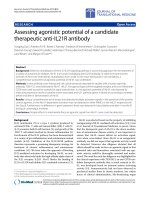
and 8). The final analysis examined the effect of medializa-
tion of the proximal femur on abductor moment arm.
This study required a change in coordinates of the femoral
head and the greater trochanter (Figure 4).
Results
The abductor moment arm of the normal femur was 5.6
centimeters in neutral standing position (Table 1).
Moment arm was greatest with superolateral displace-
ment of the greater trochanter through the entire range
of hip motion in the coronal plane (Figure 5). Equal
moment arm lengths occurred with isolated superior
displacement or lateral displacement at maximum
adduction. As the hip ranged into abduction, the later-
all y dis placed greater trochanter had a co nsid erably lar-
ger moment arm (8.8 centimeters), exceeding the
superiorly displaced greater trochanter by 21%. Inferior
displacement of the greater trochanter substantially
decreased abductor mechanical advantage in adduction,
but as the hip ranged into abduction it exceeded the
moment arm of both the normal and the superiorly dis-
placed greater trochanters. Medial displacement of the
greater trochanter resulted in the smalle st moment arm
for the entire range of motion.
Similar t o the native femur, the inferior placement of
the abductor muscle insertion site of the Biomet Finn
proximal femur endoprosthesis yielded a decreased
abductor moment arm (4.3 cm) in neutral hip position
(Table 1). This value was lowest in adduction (2.9 cm)
and increased as the hip ranged into abduction (5.1 cm).
The Biomet Finn exceeded the moment arm of the Bio-
met Letson at 10° of abduction and exceeded the Stryker
GMRS at 40° of abduction (Figure 6). The Stryker
GMRSprosthesishadthelargestmomentarminneu-
tral position (5.0 cm), 16% greater than the Finn and 9%
greater than the Letson (4.6 cm).
The GMR S and Biomet Letson prostheses, which have
prominences for abductor muscle insertion that are
superolateral to the abductor attachment site of the
Finn, had increased moment arm lengths when
abducted from neutral position, however, their values
peaked at 27° and 22° of abduction, respectively, and
then decreased. Moment arm length for th e Finn model
increased throughout abduction (Figure 6).
Increasing degrees of pelvic tilt, as seen with Trendelen-
berg gait, caused a mean decrease in abductor moment
arm for all hip configurations, with the most substantial
differences seen with inferiorly-placed abductor insertions
(Figure 7). Abductor m oment arm values through 30° o f
pelvic tilt were equivalent to values through 30° of adduc-
tion as these motions result in the same relative geometric
changes between femur and pelvis (Table 2).
Figure 2 Proximal femoral prostheses. Schematics of commercially available proximal femoral prostheses: A. Biomet Letson; B. Biomet Finn; C.
Stryker GMRS.
Henderson et al. Journal of Orthopaedic Surgery and Research 2011, 6:6
/>Page 3 of 10
Medialization of the femoral head caused a mean
increase in abductor moment arm for the adducted hip of
23% for all hip configurations (Table 3); a mean increase
of 30% was seen with the Finn and the native femur. Med-
ialization also resulted in a 34% decrease in moment arm
variance, creating a plateau effect over the range of coronal
plane motion as the simulated femur moved from 30° of
adduction to 45° of abduction (Figure 8).
Discussion
The purpose of this investigation was to characterize hip
abductor muscle moment arm through coronal plane
motion in the setting of normal anatomy, modified anat-
omy, and with the use of proximal femur endoprostheses.
The authors also sought to analyze abductor muscle
moment arm in the setting of abductor weakness.
Results of the current study demonstrate that hip
abductor moment arm is substantially affected by
changes in abductor insertion location and coronal
plane motion. Because a muscle’ smomentarmisthe
length of a line drawn perpendicular to the line of
action and intersecting the center of rotation (Figure 1),
all muscle insertions along a given line of action will
have identical moment arm values, as demonstrated in
Figure 9. Superior and lateral displacement of the
greater trochanter will move th e abductor muscle inser-
tion in a direction that increases moment arm and infer-
ior or medial displacement will move the insertion in a
direction that decreases moment arm. Because a line of
action m ust be crossed in order to change the moment
arm, combinations of inferior/lateral displacement and
superior/me dial displacement would produce little or no
change in moment arm, as depicted in Figure 9.
A corollary to be drawn from Figure 9 is that the maxi-
mum potential hip abductor moment arm can never
exceed the distance between the muscle origin and the
femoral head. Abductor moment arm attains its maximum
value lateral to the origins of the hip abductor muscles and
does not increase after this point (Figure 10). The ‘nega-
tive’ values of moment arm noted in Figure 10 indicate the
point at which the muscle insertion has moved medial to
the femoral head, in which case abductor contraction
would result in femur adduction as the muscle would
cross the joint on the opposing side, thus resulting in
‘negative’ abduction.
The curves generated by the different abductor muscle
insertion sites (F igures 5 a nd 6) demonstr ate the conse-
quences of greater trochanter manipulation. Inferior dis-
placement of the greater trochanter from its position on
the normal femur will result in a decrease in moment
arm in neutral position. As the leg abducts the moment
arm of the inferiorly displaced greater trochanter
increases and will eventually exceed that of the abducted,
unmodified greater trochanter. This occurs because the
axis of the femoral head and inferiorly displaced greater
trochant er (Figure 1) int ersects the line of muscle pull at
an angle less than 90°. As the leg abducts the angle is
increased, thereby increasing the moment arm. Conver-
sely, a superiorly-placed abductor insertion will have a
moment arm that exceeds that of the unmodif ied greater
Figure 3 Simulation of pelvic tilt. Graphic depiction of the normal
relationship of the abductor muscle origin in relation to the femoral
head (blue lines) and the position of hip abductor muscle origin
with 30° pelvic tilt (red lines).
Figure 4 Proximal femoral prostheses. Graphic depiction of the
normal relationship of the abductor muscle insertion in relation to
the femoral head (blue lines) and the position of hip abductor
muscle insertion with the femoral head after medial displacement
(red lines). The dotted lines represent the trajectory along which the
abductor muscle moment arm would be maximal.
Henderson et al. Journal of Orthopaedic Surgery and Research 2011, 6:6
/>Page 4 of 10
trochanter in neutral position. However, the moment
arm of the superiorly-displace d greater trochanter will
decrease as the leg abducts (since its angle θ is already at
or past 90° when the femur is in neutral position). Calcu-
lations from the present study show that in neutral posi-
tion the Stryker GMRS prosthesis provides a moment
arm that is 16% greater than the Biomet Finn, indicating
that the abductor force requirement to produce a given
torque is 16% less with the GMRS model. A displacement
of the greater trochanter that creates a longer moment
arm with standing and ambulation is associated with an
increase in the available resultant hip muscle force and
an accompanying decrease in joint contact force an d
required resultant force of the hip abductors [12,14];
both of which are associat ed with a favorable post opera-
tive functional outcome [11,18-20] and a decreased inci-
dence of hip prosthesis failure [21-23].
The present analysis of moment arm in the setting of
a Trendelenberg gait demonstrates that superior and lat-
eral placement of the greater trochanter provide great er
mechanical advantage through 30° of pelvic tilt. As the
pelvis leans away fr om the affected leg the angle formed
by the axes of the femoral neck and muscle fibers
becomes more acute and woul d eventually reach 0°,
causing a total loss of abductor effect (Figure 3). An
inferiorly-located abductor insertion compromises the
abductor muscles prior to rotation of the hip. Given
that Trendelenberg gait is a common complication of
proxi mal femoral replacement [1-7], the authors recom-
mend the use of a proximal component with a lateral
and/or superior abductor attachment site.
Medialization of the femoral head had two effects on
moment arm. First, it decreased the distance between joint
center and muscle origin thereby lowering the maximum
potential moment arm of the abductor unit. Second, the
trajectory of the line defining the maximum moment arm
was lowered, reducing moment arm variance. Johnston et
al. analyzed the hip resultant moment, the abductor mus-
cle force, the hip joint contact force, and the prosthetic
neck-stem bending moment in the setting of greater tro-
chanter and hip center manipulation [11]. The authors
reported that the movement of the hip center had the
greatest effect on all four quantities. All quantities were
reduced with medial and inferior placement of the joint
center, a favorable result, and were increased with superior
and lateral placement of the joint center, which is an unfa-
vorable result. Lateral displacement of the abductor mus-
cle insertion resulted in smaller reductions in all quantities
except the joint resultant moment, which remained
unchanged. The effect of medial displacement of the hip
center on the joint contact force and the resultant hip
moment far outweighed those of l ateralizing the greater
trochanter. This finding seems to contradict the modest
advantage in m oment arm afforded by movement of the
Table 1 Abductor Moment Arm for Commerical Prostheses and Native Femur
Muscle Division Position Abductor Moment Arm (cm)
Biomet - Letson Biomet - Finn Stryker - GMRS Native Femur
30° Adduction 4.2 3.6 4.5 4.5
Anterior Neutral 4.9 4.8 5.4 6.0
45° Abduction 3.5 5.2 4.4 7.4
30° Adduction 3.6 2.9 3.8 3.7
Gluteus Medius Middle Neutral 4.7 4.3 5.1 5.4
45° Abduction 4.6 5.4 5.4 7.2
30° Adduction 2.8 2.0 2.9 2.6
Posterior Neutral 4.0 3.5 4.2 4.2
45° Abduction 5.0 5.0 5.5 6.2
30° Adduction 4.6 4.1 5.0 5.5
Anterior Neutral 5.0 5.2 5.6 7.1
45° Abduction 2.5 4.5 3.0 7.3
30° Adduction 3.8 3.0 4.0 4.0
Gluteus Minimus Middle Neutral 4.8 4.5 5.3 6.1
45° Abduction 4.3 5.4 5.0 7.8
30° Adduction 2.7 1.8 2.8 2.4
Posterior Neutral 4.0 3.4 4.3 4.5
45° Abduction 5.0 5.2 5.6 6.9
30° Adduction 3.6 2.9 3.8 3.8
Mean All Divisions Neutral 4.6 4.3 5.0 5.6
45° Abduction 4.2 5.1 4.8 7.1
Henderson et al. Journal of Orthopaedic Surgery and Research 2011, 6:6
/>Page 5 of 10
hip center. However, the primary benefit of medial displa-
cement of the hip center has a minimal correlation with
increasing the moment arm of the abductor muscles.
Instead, this significant advantage is due to the consequent
decrease in moment arm and resultant moment of the
body itself (Figure 11). This reduces the lever arm and the
fraction of bodyweight that contributes to the resultant
moment, thereby reducing both components of torque. It
is this moment that the abductors must balance in order
to maintain a one-legged stance. The authors of the
current investigation believe that optimizing functional
outcomes in patients undergoing proximal femoral repla-
cement is best achieved with a combination of joint center
medialization and selection of a prosthesis that provides
the maximum moment arm in single-leg stance.
The authors recognize weaknesses in the current
study. The present model is based on previously pub-
lished coordinates that represent a normal hip. Anato-
mical variation between patients will cause moment
arm values with and without surgical manipulation to
vary from our results. Furthermore, our model is a two-
dimensional representation of a three-dimensional
construct. Preliminary calculations using a three-
dimensional model, however, showed no substantial dif-
ference from the two-dimensional model findings with a
maximum change of 3.4% from the t wo-dimensional
calculations. Other invest igations of the hip abductor
Figure 5 Hip abductor moment arm plot for normal femur.
Line plot showing mean hip abductor moment arm through
coronal plane motion for the normal femur (black) and femurs with
greater trochanter displacements 2 cm medial (orange), 2 cm
inferior (yellow), 2 cm (superior) green, 2 cm lateral (blue), 2 cm
superior and 2 cm lateral (red).
Figure 6 Hip abductor moment arm plot for proximal femur
prostheses. Line plot showing mean hip abductor moment arm
through coronal plane motion for the normal femur (black), Biomet
Finn prosthesis (green), Biomet Letson prosthesis (red), and Stryker
GMRS prosthesis (blue).
Figure 7 Effect on hip abductor moment arm with pelvic tilt.
Line plot showing mean abductor moment arm of the hip joint in
neutral position through 30˚ of pelvic tilt for the normal femur
(black), Biomet Finn prosthesis (green), Biomet Letson prosthesis
(red), and Stryker GMRS prosthesis (blue).
Henderson et al. Journal of Orthopaedic Surgery and Research 2011, 6:6
/>Page 6 of 10
muscles have confined their analyses to the frontal plane
citing similar results [15,24]. Although it is an accepted
alternative to abductor-to-prosthesis repair, we did not
attempt to simulate soft-tissue attachment of the abduc-
tor unit due to the myriad of confounding factors when
simulating a viscoelastic medium. The numerical data
presented here should not be assumed to be absolute.
Instead we wish the surgeon to place emphasis on the
concepts and consequences of manipulating native hip
joint geometry and how this may be tailored to benefit
patients whose compensatory mechanisms or proce-
dure-specific functional prognosis are limited.
Conclusions
Hip abductor moment arm varies substantially through-
out the hip’ s range of motion in the coronal plane.
Lateral and superior movement o f the hip abductor
muscle insertion will increase moment arm and medial
and inferior will decrease their moment arm for single-
leg stance. Selection of an endoprosthesis that optimizes
hip abductor moment arm will reduce the forces
required of the abductor muscles to maintain gait.
Reducing the abductor forces required for single-leg
stance may help preserve normal ambulation in patients
receiving proximal femoral replacement.
Table 2 Abductor Moment Arm in Neutral Stance with 30° Pelvic Tilt
Muscle Division Abductor Moment Arm (cm)
Biomet - Letson Biomet - Finn Stryker - GMRS Native Femur
Anterior 4.2 3.6 4.5 4.5
Gluteus Medius Middle 3.6 2.9 3.8 3.7
Posterior 2.8 2.0 2.9 2.6
Anterior 4.6 4.1 5.0 5.5
Gluteus Minimus Middle 3.8 3.0 4.0 4.0
Posterior 2.7 1.8 2.8 2.4
Mean 3.6 2.9 3.8 3.8
Change from 0° Tilt -22% -33% -24% -32%
Table 3 Abductor Moment Arm with Medialization of Femoral Head
Muscle Division Position Abductor Moment Arm (cm)
Biomet - Letson Biomet - Finn Stryker - GMRS Native Femur
30° Adduction 4.6 4.5 4.9 5.5
Anterior Neutral 5.0 5.0 5.4 6.3
45° Abduction 4.1 5.4 5.0 7.3
30° Adduction 4.1 3.9 4.4 4.7
Gluteus Medius Middle Neutral 4.7 4.6 5.1 5.8
45° Abduction 4.9 5.4 5.6 7.0
30° Adduction 3.4 3.1 3.6 3.7
Posterior Neutral 4.0 3.9 4.3 4.6
45° Abduction 4.9 4.8 5.2 5.7
30° Adduction 4.8 4.8 5.3 6.3
Anterior Neutral 5.0 5.3 5.6 7.3
45° Abduction 3.3 4.8 3.8 7.5
30° Adduction 4.2 3.9 4.6 5.1
Gluteus Minimus Middle Neutral 4.8 4.8 5.3 6.4
45° Abduction 4.8 3.4 5.4 7.7
30° Adduction 3.3 2.9 3.5 3.6
Posterior Neutral 4.1 3.8 4.4 4.9
45° Abduction 5.0 5.0 5.5 6.5
30° Adduction 4.1 3.9 4.4 4.8
Mean All Divisions Neutral 4.6 4.6 5.0 5.9
45° Abduction 4.5 4.8 5.1 7.0
Henderson et al. Journal of Orthopaedic Surgery and Research 2011, 6:6
/>Page 7 of 10
Appendix
rrsin
⊥
= *
θ
(1)
Where r is the lever arm length defind as the femoral
head-to-abductor insertion point distance in the case of
the hip, and θ is equal to the angle between r and the
line of muscle pull.
r[(x x) (y y)]
pi
2
pi
20.5
=+
(2)
q
=−−−−−[arctan[( ) / ( )] arctan[( ) /( )]]yy xx yy xx
oi oi pi pi
(3)
r [[(x x ) (y y ) ] ] sin[arctan[(y y )/(x x )]
a
pi
2
pi
20.5
oioi⊥
=+−− −−
−
*
rrctan[(y y )/(x x )]]
pipi
−−
(4)
x
rcos
i
=−*( )
ab
(5)
y
rsin
i
=−*( )
ab
(6)
Where (r * cos a)and(r*sina) are polar coordinate
equivalents fo r x
i
and y
i
, respect ively, and b is the angle
Figure 8 Hip abductor moment arm with femoral head
medialization. Line plot showing mean hip abductor moment arm
with medialized femoral head through coronal plane motion for the
normal femur (black), Biomet Finn prosthesis (green), Biomet Letson
prosthesis (red), and Stryker GMRS prosthesis (blue) - plots of
configurations without medialization shown in dashed lines.
Figure 9 Coronal view demonstrating potential lines of abductor pull and resultant moment arm lengths. Coronal view of hip showing
potential lines of abductor muscle pull (dotted lines) radiating from a point approximating the middle division of gluteus medius and the
corresponding abductor moment arm lengths (solid lines). Movement of the abductors’ insertion in the direction of the red positive sign (lateral
or superior) would result in lengthening of the abductor moment arm. Movement of the abductors’ insertion in the direction of the blue
negative sign (medial or inferior) would result in shortening of the abductor moment arm.
Henderson et al. Journal of Orthopaedic Surgery and Research 2011, 6:6
/>Page 8 of 10
Figure 10 Three-dimensional plot of abductor moment arm. Three-dimensional plot of abductor moment arm for a right hip where the x-y
projection represents the coronal plane, the hip center is located at (0,0,0), and the z axis represents abductor moment arm. Abductor moment
arm achieves a maximum value lateral to the abductor origin and does not increase if the insertion is moved further lateral. Negative moment
arm values are possible medially where abductor muscle firing would result in adduction.
Figure 11 Resultant hip moment. Graphic depiction of the normal hip resultant moment (blue line) and the hip resultant moment when the
femoral head has been medialized (red line).
Henderson et al. Journal of Orthopaedic Surgery and Research 2011, 6:6
/>Page 9 of 10
of abduction. These substitutions were made for equa-
tion 5 and a plot was generated of r
⊥
as a function of b.
x
[(x x ) (y y ) ] cos( )
oi o p
2
op
20.5
=+−− −*
cd
(7)
y
[(x x ) (y y ) ] ( )
oi o p
2
op
20.5
=+−− −*sin
cd
(8)
Where c is the polar coordinate angle for the muscle
origin wi th 0° pelvic ti lt and δ is the angle of pelvic tilt.
Again, these substitutions were made for equation 5 and
aplotwasgeneratedofr
⊥
as a function of δ,whose
values ranged from zero ° to 30°.
Acknowledgements
The authors wish to thank W. Richard Stark (University of South Florida,
Department of Mathematics) for his tutelage on the use of Maple 9.0.
The authors also wish to thank Ross P. Henderson (Florida State
University, Department of N euroscience) for checking our mathematical
calculations.
Author details
1
Department of Orthopaedics and Sports Medicine, 13220 Laurel Drive,
University of South Florida, Tampa, Florida, 33612, USA.
2
Sarcoma Division,
12902 Magnolia Drive, H. Lee Moffitt Cancer & Research Institute, Tampa,
Florida, 33612, USA.
3
Orthopaedic Oncology Division, Department of
Orthopaedic Surgery, University of Miami, Miami, Florida, USA.
Authors’ contributions
ERH derived the mathematical model, conducted the literature search,
collected the data, and participated in the writing of the manuscript. GAM
and DC provided editorial input and aided in the writing of the manuscript.
HTT and GDL oversaw the design of the investigation, construction of the
mathematical model, aided with data analysis, and aided with manuscript
writing. All authors read and approved the final manuscript.
Authors’ information
ERH - Fifth year orthopaedic surgery resident, University of South Florida,
Tampa, USA
GAM - Fourth year orthopaedic surgery resident, University of South Florida,
Tampa, USA
DC - Orthopaedic oncologist, Moffitt Cancer Center & Research Institute,
Tampa, USA
HTT - Vice Chairman and Orthopaedic oncologist, University of Miami,
Miami, USA
GDL - Division Chief and Orthopaedic oncologist, Moffitt Cancer Center &
Research Institute, Tampa, USA
Competing interests
The authors wish to disclose that GDL and HTT are design consultants for
Stryker Orthopaedics. The authors also wish to disclose that DC is a design
consultant for Salient Surgical Technolo gies.
Received: 11 May 2010 Accepted: 25 January 2011
Published: 25 January 2011
References
1. Donati D, Zavatta M, Gozzi E, Giacomini S, Campanacci L, Mercuri M:
Modular prosthetic replacement of the proximal femur after resection of
a bone tumour a long-term follow-up. Journal of Bone and Joint Surgery
(Br) 2001, 83:1156-1160.
2. Haentjens P , De B oeck H, Opdecam P: Proximal femoral r eplacement prosthesis
for s alvage of failed hip arthroplasty: complications in a 2-11 y ear follow-up
study in 1 9 elderly pat ients. Acta Orthopaedica Scandinavica 1996, 67 :37-42.
3. Johnsson R, Carlsson A, Kisch K, Moritz U, Zetterstrom R, Persson BM:
Function following mega total hip arthroplasty compared with
conventional total hip arthroplasty and healthy matched controls.
Clinical Orthopaedics and Related Research 1985, 159-167.
4. Kotz R, Ritschl P, Trachtenbrodt J: A modular femur-tibia reconstruction
system. Orthopedics 1986, 9:1639-1652.
5. Sim F, Chao E: Hip Salvage by Proximal Femoral Replacement. Journal of
Bone and Joint Surgery (Am) 1981, 63:1228-1239.
6. Zehr RJ, Enneking WF, Scarborough MT: Allograft-prosthesis composite
versus megaprosthesis in proximal femoral reconstruction. Clinical
Orthopaedics and Related Research 1996, 207-223.
7. Zwart H, Taminiau A, Schimmel J, van Horn J: Kotz Modular Femur and
Tibia Replacement. Acta Orthopaedica Scandinavica 1994, 65:315-318.
8. Gehlsen G, Whaley M: Falls in the elderly: Part II, Balance, strength, and
flexibility. Archives of Physical Medicine & Rehabilitation 1990, 71:739-741.
9. Whipple R, Wolfson L, Amerman P: The relationship of knee and ankle
weakness to falls in nursing home residents: an isokinetic study. Journal
of the American Geriatrics Society 1987, 35:13-20.
10. Guralnik J, Ferrucci L, Simonsick E, Salive M, Wallace R: Lower-extremity
function in persons over the age of 70 years as a predictor of
subsequent disability. New England Journal of Medicine 1995, 332:556-561.
11. Johnston R, Brand R, Crowninshield R: Reconstruction of the hip. A
mathematical approach to determine optimum geometric relationships.
Journal of Bone and Joint Surgery (Am) 1979, 61:639-652.
12. Antolic V, Iglic A, Herman S, Srakar F, Iglic V, Lebar A, Stanic U: The
required resultant abductor force and the available resultant abductor
force after operative changes in hip geometry. Acta Orthopaedica Belgica
1994, 60:371-377.
13. Crowninshield R, Johnston R, Andrews J, Brand R: A biomechanical
investigation of the human hip. Journal of Biomechanics 1978, 11:75-85.
14. Iglic A, Antolic V, Srakar F, Kralj-Iglic V, Macek-Lebar A, Brajnik D:
Biomechanical study of various greater trochanter positions. Archives of
Orthopaedic and Trauma Surgery 1995, 114:76-78.
15. Inman V: Functional Aspects of the Abductor Muscles of the Hip. Journal
of Bone and Joint Surgery (Am) 1947, 29:607-619.
16. Dostal W, Andrews J:
A three-dimensional biomechanical model of hip
musculature. Journal of Biomechanics 1981, 14:803-812.
17. Jensen R, Davy D: An investigation of muscle lines of action about the
hip: a centroid line approach vs the straight line approach. Journal of
Biomechanics 1975, 8:103-110.
18. Kummer B: Die klinische Relevanz biomechanischer Analysen der
Huftregion. Z Orthop Ihre Grenzgeb 1991, 129:285-294.
19. Pauwels F: Biomechanics of the normal and diseased hip: Theoretical
foundation, technique and results of treatment New York: Springer; 1976.
20. Srakar F, Iglic A, Antolic V, Herman S: Computer simulation of
periacetabular osteotomy. Acta Orthopaedica Scandinavica 1992,
63:411-412.
21. Gritzka T, Fry L, Cheesman R, LaVigne A: Deterioration of articular cartilage
caused by continuous compression in a moving rabbit joint. A light and
electron microscopic study. Journal of Bone and Joint Surgery (Am) 1973,
55:1698-1720.
22. Mitchell N, Lee E, Shepard N: The clones of osteoarthritic cartilage. Journal
of Bone and Joint Surgery (Am) 1992, 74:33-38.
23. Ogata K, Whiteside L, Lesker P, Simmons D: The effect of varus stress on
the moving rabbit knee joint. Clinical Orthopaedics and Related Research
1977, 129.
24. Olson V, Smidt G, Johnston R: The maximum torque generated by the
eccentric, isometric, and concentric contractions of the hip abductor
muscles. Physical Therapy 1972, 52:149-158.
doi:10.1186/1749-799X-6-6
Cite this article as: Henderson et al.: Hip abductor moment arm - a
mathematical analysis for proximal femoral replacement. Journal of
Orthopaedic Surgery and Research 2011 6:6.
Henderson et al. Journal of Orthopaedic Surgery and Research 2011, 6:6
/>Page 10 of 10