Inspection of Vertical Transportation Equipment_3 ppt
Bạn đang xem bản rút gọn của tài liệu. Xem và tải ngay bản đầy đủ của tài liệu tại đây (358.55 KB, 27 trang )
2-35
Simpo PDF Merge and Split Unregistered Version -
2-36
Simpo PDF Merge and Split Unregistered Version -
2.9.2 In-Car Inspection
2.9.2.1 Drive. If the screw machine is mounted on the car and accessible for inspection and
maintenance from an access panel in the side or rear car wall, check the access panel to verify
that it is normally kept closed and locked and that the key is available only to inspectors,
maintenance personnel and repair personnel. Insure that the machine cannot be operated when
the access panel is open. If the screw machine is equipped with a safety nut below the drive nut,
carefully measure the space (distance) between the drive nut and the safety nut. Compare this
space with the space when the drive nut and safety nut were originally installed by referring to
the Safety Nut Spacing Data Tag attached to the screw machine. A reduction in this space is an
indication of wear of the drive nut. Any reduction of the separation space of more than one
thirty-second (1/32) inch should be reported. Examine any belts or chains in the screw machine
drive for proper tension, wear and damage; including cuts, breaks, or separation. Check
tension devices, if provided, to verify that they are in proper adjustment to detect slack or broken
belts or chains. Check all machine fastening bolts to determine that none have become loose or
are missing. Visually inspect the electrical service connection to the motor to verify there is not
evidence of chafing, damage, or looseness. Inspect the screw column to verify that it is
lubricated in accordance with manufacturer's recommendations. After temporarily making the
contact on the access panel inoperative so that the screw machine can be operated with the access
panel open, operate the elevator car in each direction while observing the brake functions and the
rotation of the machine. Promptly upon interruption of power to the drive machine, stop the car.
2.9.2.2 Control Equipment. If the controller is located on the car and accessible for inspection
and maintenance from an access panel in the side or rear car wall, proceed with the inspection as
described previously in this chapter.
2.9.2.3 Hoistway Equipment. If the particular design and installation permits the inspection of
all mechanical and electrical equipment from within the car, the contact for the access panel
should be made inoperative temporarily so that the car can be moved with the access panel open.
Start with the car at the top of the hoistway and move the car in the down direction in about two
(2) foot increments, stopping to inspect all hoistway equipment at each location. Included in the
mechanical and electrical equipment which should be inspected are: guide rails, guide rail
fastenings; screw column supports, mounting brackets and guides, traveling cable, etc.
2-37
Simpo PDF Merge and Split Unregistered Version -
The inspection should verify that all hoistway equipment is undamaged and functional and that
all fastenings are tight. If the screw column is in tension, verify that the support fastenings at or
near the top of the hoistway are tight and there is no evidence of damage or distortion. If the
screw column is in compression, verify that the support means at or near the bottom of the
hoistway are intact and there is not evidence of damage or distortion. Check screw column
guides or stabilizing supports to verify that they are intact and functional. If the screw column is
made up of more than one section, special attention should be given to the joints to verify
that there is no indication of shifting or separation of the sections. Utilize procedure previously
described in this chapter for inspection of items common to screw column and traction elevators.
observe extreme care when moving the car with the access panel open. Be sure the contact on
the access panel is restored for normal operation and that the access panel is properly closed and
locked before leaving the car.
2.9.3 Outside Of Hoistway Inspection
2.9.3.1 Control Equipment. Control equipment may be located separate from the elevator. If
this arrangement is used, then the equipment must be enclosed in a locked metal cabinet with
access restricted. Inspection procedures should be as previously described in this chapter.
2.9.3.2 Manual Movement of a Stalled Car. If the elevator is equipped with a device to permit a
qualified person, from a position outside the elevator car, to manually move the car to a landing,
check the operation as follows:
a. Have the power-supply-line disconnecting means opened while the car is between landings
to simulate an unplanned power outage.
b. Operate the device manually and move the car to an adjacent landing.
c. Restore the device and the power-supply-line disconnecting means for manual operation.
2.9.4 Top Of Car Inspection
2.9.4.1 Drive. If the screw machine is located on, or accessible from, the top of the car, proceed
with the inspection in accordance with the procedures previously described in this section.
2.9.4.2 Control Equipment. Control equipment may be located on the car top. Proceed with the
inspection as previously described in this section.
2-38
Simpo PDF Merge and Split Unregistered Version -
2.9.4.3 Speed Governor, Governor Rope and Governor Rope Releasing Carrier. If the elevator
is equipped with a speed governor which is most accessible from the top of the car, inspect the
governor in accordance with the applicable portions of Item 104.6 of the A17.2 Manual. Inspect
the governor rope releasing carrier, if the elevator is so equipped, in accordance with the
applicable portions of Item 103.15 and the governor rope in accordance with the applicable
portions of 103.4.
2.9.5 Inspection Of Machine Rooms And Machinery Space.
In some applications, the drive system, control equipment and/or speed governor are located in
a specific machine room or machinery space. Inspection procedures for such an arrangement
shall follow the steps previously described in Section 2.5 "OVERHEAD MACHINERY SPACE
AND MACHINE ROOM INSPECTION" and, for general requirements relating to this type of
arrangement, as previously described for traction elevator.
2.9.6 Periodic Inspections And Tests
The following inspections and tests should be made on a periodic basis.
2.9.6.1 Annual Inspections and Tests.
2.9.6.1.1 Terminal Stopping Devices. See Division 116 of the A17.2 Manual for inspection and
test of normal terminal stopping devices. Note that final terminal stopping devices are not
required on screw column elevators having a rated speed of less than 100 fpm. Mechanical steps
are allowed. Where final terminal stopping devices are provided, test by adjusting the
device with the car operating at leveling speed.
2.9.6.1.2 Governor and Safety Test. Where governors and safeties are provided on screw
column elevators, they should be tested as outlined in Divisions 111 and 112 of A17.2.
2-39
Simpo PDF Merge and Split Unregistered Version -
2.9.6.1.3 Buffer Test. Where oil buffers are provided on screw column elevators, they should
be tested as outlined in Division 114 of A17.2. There is no requirement to perform a test of
spring buffers.
2.9.6.1.4 Test of Firefighter's Service. Where the Firefighter's Service is provided on screw
column elevators, they should be tested as previously outlined for traction elevators in this
chapter. On Section 2.10 - "FIREFIGHTER'S SERVICE".
2.9.6.1.5 Test of Emergency Power Operation. Where emergency power is provided for screw
column elevators, it should be tested as outlined in applicable portions of Division 117 of A17.2.
2.9.6.1.6 Test of Closing Force of Door System. Where screw column elevators are provided
with power operated doors, the closing force of the door system should be tested as outlined in
applicable portions of Division 119 of A17.2.
2.9.6.2 Tests Performed Each Five Years.
2.9.6.2.1 Oil Buffers. Where oil buffers are provided on screw column elevators, they should be
tested as outlined in applicable portions of Division 115 of A17.2. There is no requirement to
perform a test of spring buffers.
2.9.6.2.2 Governor and Safety Test. Where governors and safeties are provided on screw
column elevators, they should be tested as outlined by applicable portions of Division 113 of
A17.2.
2-40
Simpo PDF Merge and Split Unregistered Version -
2-41
Simpo PDF Merge and Split Unregistered Version -
2-42
Simpo PDF Merge and Split Unregistered Version -
2-43
Simpo PDF Merge and Split Unregistered Version -
2-44
Simpo PDF Merge and Split Unregistered Version -
2-45
Simpo PDF Merge and Split Unregistered Version -
CHAPTER 3
HYDRAULIC ELEVATORS
3.1 INTRODUCTION
NOTE: Paragraphs identified with a vertical line in the left margin are inspections that should
be made by certified Vertical Transportation Equipment Inspectors only.
3.1.1 Scope
The inspection procedure for hydraulic elevators included in this chapter is not only an
inspection of all safety related functions, but is also an inspection to determine the condition of
the equipment and identify areas that need improvement. Proper maintenance is needed to keep
the elevator operating. When preventive maintenance is lacking, shut downs will occur. Part II
of the ANSI/ASME A17.2 Inspector's Manual for Elevators and Escalators addresses the safety
aspect of the inspection of hydraulic elevators. In this chapter we will identify the specific
Division of Part II which relates directly to the inspection procedure being followed in this
text. It is intended that each noted division should be reviewed as it is identified and suggested
procedures followed. The maintenance and performance considerations of the inspection will be
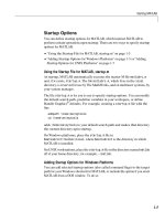
addressed in the following test. See Figures 3-1 and 3-2, which show various elevator
arrangements with component names that will be used in this chapter.
3.1.2 Performance Criteria
As was stated, the purpose of procedures as outlined in Section 2.1.2 are applicable.
3.1.2.1 Elevator Speed (Hydraulic Elevators). Elevator operating speed is measured with a
tachometer while the elevator makes a full run through the hoistway with no load in the car.
With hydraulic elevators, it is necessary to make this reading from the top of the car by holding
the tachometer on the guide rail. The up direction operating speed should be maintained at a
level of plus or minus 5% of the rated speed (to be found on the cross head of the car) under any
load condition. The down speed is much more difficult to obtain because the speed is directly
related to the weight in the car. Usual adjustments are made such that contract speed is obtained
in the down direction with 50% load on the car. The empty car down speed should be
maintainable at about 10% below contract speed and full load down speed should be
maintainable at about 10% above contract speed.
3-1
Simpo PDF Merge and Split Unregistered Version -
3-2
Simpo PDF Merge and Split Unregistered Version -
3-3
Simpo PDF Merge and Split Unregistered Version -
3.1.2.2 Door Opening Time. Procedures as outlined in Section 2.1.2.1 are applicable.
3.1.2.3 Door Closing Time. Procedures as outlined in Section 2.1.2.3 are applicable.
3.1.2.4 Door Hold Open Time. Procedures as outlined in Section 2.1.2.4 are applicable.
3.1.2.5 Door Closing Force. Procedures as outlined in Section 2.1.2.5 are applicable.
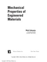
3.1.2.6 Performance Times (floor to floor times). Procedures as outlined in Section 2.1.2.6 are
applicable. A calculated reasonable standard time for various types of elevators are shown in
Table 3-1.
3.1.2.7 Acceleration, Deceleration, Floor Stopping And Noise. Procedures as outlined in Section
2.1.2.7 are applicable.
3.2 INSIDE THE CAR INSPECTION
3.2.1 Scope
Division 201 of the A17.2 Manual covers the inspections made from inside hydraulic elevator
cars.
3.2.2 Operating And Signalling Devices
Procedures as outlined in Section 2.2.2 are applicable.
3.2.3 Car Enclosure
Procedures as outlined in Section 2.2.3 are applicable.
3.2.4 Car Doors
Procedures as outlined in Section 2.2.4 are applicable.
3.2.5 Car Sill
Procedures as outlined in Section 2.2.5 are applicable.
3.2.6 Freight Elevator Enclosures
Procedures as outlined in Section 2.2.6 are applicable.
3-4
Simpo PDF Merge and Split Unregistered Version -
TABLE 3-1
HYDRAULIC ELEVATORS
FLOOR-TO-FLOOR PERFORMANCE TIME SELECTION
Times in Seconds
Tolerance - plus or minus .2 seconds
ADJUSTMENT
PER FOOT
OF TRAVEL
SPEED DOOR TYPE AND OPENING WIDTH[1] FROM 12'-0"
(F.P.M.) SIDE OPENING STANDARD[2]
36" 42" 48" 54" (SECONDS)
50 21.5 22.5 23.5 24.5 1.2
75 17.5 18.5 19.5 20.5 0.8
100 15.5 16.5 17.5 18.5 0.6
125 14.5 15.5 16.5 17.5 0.5
150 13.5 14.5 15.5 16.5 0.4
CENTER OPENING
50 19.5 20.0 20.5 21.0 1.2
75 15.5 16.0 16.5 17.0 0.8
100 13.5 14.0 14.5 15.0 0.6
125 12.5 13.0 13.5 14.0 0.5
150 11.5 12.0 12.5 13.0 0.4
1. Values are based on 7'-0" to 7'-6" high doors. Adjust values for 7'-6" to 8'-6" high doors, by
adding the following factor:
1/2 second for widths up to 42"
1 second for widths over 42"
2. Values are based on 12'-0" floor-to-floor height. Adjust using factors noted for variation
from this standard.
Find rated speed in the 1st column. Select standard floor-to-floor performance time from box
under correct door type (side opening or center opening) and clear door opening width. Adjust
this time by adding factor if doors are over 7'-6" high, and adding or subtracting appropriate
amount per foot of travel over or under standard floor height of 12"-0".
3-5
Simpo PDF Merge and Split Unregistered Version -
NOTE: All times are based on heavy duty, medium speed, door operating equipment and
optimum adjustment.
3.2.7 Firefighter's Service Instructions
Instructions as outlined in Section 2.2.7 are applicable.
3.2.8 Performance
Procedures as outlined in Section 2.2.8 are applicable.
3.3 OUTSIDE THE CAR INSPECTION
3.3.1 Hoistway Entrance
Division 202 of the A17.2 Manual covers the inspections made from outside hydraulic
elevator cars. Items and procedures as outlined in Section 2.3.1 are applicable.
3.3.2 Closing Force
Instructions as outlined in Section 2.3.2 are applicable.
3.3.3 Access Switch Operation
Items and procedures as outlined in Section 2.3.3 are applicable.
3.3.4 Emergency Key Access
Items and procedures as outlined in Section 2.3.4 are applicable.
3.3.5 Operation And Signalling Devices
Procedures as outlined in Section 2.3.5 are applicable.
3.3.6 Firefighter's Service Instructions
Instructions as outlined in section 2.3.6 are applicable.
3-6
Simpo PDF Merge and Split Unregistered Version -
3.4 CAR TOP INSPECTION
3.4.1 Scope
Division 203 of the A17.2 covers most of the inspections made from the top of hydraulic
elevators. Procedures as outlined in Section 2.4.1 are applicable.
3.4.2 Anti-Creep
Item 203.1 of the A17.2 Manual covers the testing of the anti-creep leveling devices. Be
advised, that even though the A17.1 Code and A17.2 Manual relate to a particular anti-creep
device, it is more of a function that is being checked and not a specific device. Most
manufacturers incorporate the anti-creep operation into the normal leveling function using
their usual floor position system. It is important that this anti-creep test be conducted on every
inspection. This function prevents the car from drifting away from the floor. It should function
with the emergency stop in the car in the open position and this should be checked. It should not
operate if the emergency stop switch in the top of car operating device is open.
3.4.3 Car Top
Procedures as outlined in Section 2.4.3 are applicable.
3.4.4 Door Operator
Procedures as outlined in Section 2.4.4 are applicable.
3.4.5 Hoistway Entrances
Procedures and figures as outlined in Section 2.4.5 are applicable.
3.4.6 Covers And Guards
Procedures as outlined in Section 2.4.6 are applicable.
3.4.7 Hoistway Ventilation
Procedures as outlined in Section 2.4.7 are applicable.
3.4.8 Wiring
Procedures as outlined in Section 2.4.8 are applicable.
3-7
Simpo PDF Merge and Split Unregistered Version -
3.4.9 Guides
Procedures as outlined in section 2.4.9 are applicable.
3.4.10 Hoistway Housekeeping
Procedures as outlined in Section 2.4.10 are applicable.
3.4.11 Operating Speed
The elevator speed should be checked with a tachometer to verify that the elevator is operating
at rated speed. An elevator operating below rated speed is not providing full service and should
be adjusted. occasionally, an elevator is found operating over the rated speed.
3.5 OVERHEAD MACHINERY SPACE OR MACHINE ROOM
3.5.1 Scope
Division 204 of the A17.2 Manual describes the various inspections that
are made in the machinery space or machine room. However, the inspector must
go beyond these areas and closely examine all the elevator equipment.
3.5.2 Main Line Switch
Procedures as outlined in Section 2.5.2 are applicable.
3.5.3 Relief Valve
The A17.1 Code and A17.2 Manual specifically addresses the inspection requirements for the
relief valve. (The operation of this device prevents the building of pressure in the system beyond
a set limit if for some reason the elevator landed on the stop ring or was blocked from moving up
the hoistway). The certified inspector should follow the steps outlined in the A17.2 Manual as
close as possible to assure nothing is overlooked. Be sure the seal is in place and that it is
properly located. The seal most used is the lead block and wire type, but there are other types
which provide the same degree of security. The seal is used to indicate whether adjustments
have been modified from the set position. Be sure that seals are placed in such a position that it
is broken if adjustment changes are made. Occasionally, seals are found in a position that
modification can be made and the seal remains intact.
3-8
Simpo PDF Merge and Split Unregistered Version -
3.5.4 Oil Leakage
Item 204.6 of the A17.2 Manual relates to checking for excessive oil in drip pans under the
pump unit. Good maintenance will keep oil leakage to a minimum. There will be some because
of vibration, but it can be kept to a minimum. Some pump units are designed where components
are housed in the oil storage tank. (See Figure 3-3 and 3-4) One of the reasons for this is to
reduce the need for tight fittings. Leakage indicates a potential problem and, when found, the
problem should be corrected.
3-9
Simpo PDF Merge and Split Unregistered Version -
3-10
Simpo PDF Merge and Split Unregistered Version -
3.5.5 Guards
Procedures as outlined in Section 2.5.5 are applicable.
3.5.6 Bearings
A thorough check of the pump motor and pump bearings should be made on each inspection
trip. Problems in these areas do not happen over night. If found early, they can greatly reduce
repair costs and time. Bearing problems are detected by sound and/or heat.
3.5.7 Control Equipment
The A17.2 Manual outlines a complete inspection of the control equipment. Special attention
should be given to the following specific items:
a. Condition of relay contacts and shunts.
b. Broken or cracked resistance tubes or resistance grids.
c. Condition of fuses and that they are sized in accordance with manufacturer's requirements.
d. Contact arcing and damage resulting from arcing.
e. Contact alignment.
f. Excessive heating of coils and resistance and damage resulting from heat.
3.5.8 Machine Room
Procedures as outlined in Section 2.5.12 are applicable.
3.5.9 Machine Room Access
Procedures as outlined in Section 2.5.13 are applicable.
3.6 PIT INSPECTION
3.6.1 Scope
Division 205 of A17.2 Manual describes the various inspections which are made in the pit.
These should be followed very closely. The beginning of Division 105 describes various safety
precautions that should be followed when making this part of the inspection.
3.6.2 Housekeeping
Procedures as outlined in section 2.6.2 are applicable.
3-11
Simpo PDF Merge and Split Unregistered Version -
3.7 PERIODIC INSPECTION AND TESTS
3.7.1 Scope
Division 210 of the A17.2 Manual describes various operational tests that are required to be
performed. Those included under item 210.1 are to be performed annually while those under
210.2 are every three years and under 210.3 every five years. It should be specifically
documented on the inspector's report that these tests have been performed, plus the dates the
tests were made.
3.7.2 Standby Power
Procedures as outlined in section 2.7.8 are applicable.
3.7.3 Door Closing Force
Procedures as outlined in Section 2.7.9 are applicable.
3.7.4 Firefighter's Service
Procedures as outlined in Section 2.7.10 are applicable.
3-12
Simpo PDF Merge and Split Unregistered Version -
3-13
Simpo PDF Merge and Split Unregistered Version -
3-14
Simpo PDF Merge and Split Unregistered Version -