Báo cáo hóa học: " Adjustable TXOP mechanism for supporting video transmission in IEEE 802.11e HCCA" potx
Bạn đang xem bản rút gọn của tài liệu. Xem và tải ngay bản đầy đủ của tài liệu tại đây (1.24 MB, 16 trang )
RESEARCH Open Access
Adjustable TXOP mechanism for supporting video
transmission in IEEE 802.11e HCCA
Aphirak Jansang and Anan Phonphoem
*
Abstract
The basic mechanism of HCCA (HCF Control Channel Access) has been introduced in IEEE 802.11e standard to
support the parameterized QoS by allocating a fixed duration based on the requested TSPEC requirements during
the admission control process. However, the variable bit rate (VBR) traffic (e.g., MPEG-2 and MPEG-4 video) cannot
be surely supported. In this study, the adjustable TXOP mechanism for supporting video transmission, ATMV, has
been proposed. The mechanism adaptively adjusts the TXOP duration acco rding to a finite state machine based on
feedback queue size information. The mecha nism aims for prompt serving burst packets, generated from the
incoming video frames, which finally minimizes the packet delay. Both system performance (mean packet delay,
TXOP loss factor, and channel occupancy) and video quality (PSNR and MOS values) have been evaluated from five
video clips in three categories by using the network simulator, NS2, with EvalVid toolset. The result s reveal that the
proposed mechanism performs well for rapid movement video category and adequately supports for other video
categories.
Keywords: IEEE 802.11e, quality of service, variable bit rate, finite sta te machine
1 Introduction
To support quality of service (QoS) in I EEE 802.11 [1],
the IEEE 802.11e task group [2] was setup. The standard
has been rectified since 2005 based on its legacy IEEE
802.11 Distributed Coordination Function (DCF) and
Point Coordination Function (PCF) modes. Two
extended modes are proposed: Enhanced Distributed
Channel Access (EDCA) and HCF Controlled Channel
Access (HCCA). The EDCA mode is the next generation
of DCF mode that aims for supporting prioritized QoS.
EDCA raises voice or video traffic priority over the
background traff ic, such as Web and FTP, by differen-
tiating its contention window (CW) and interframe
space (IFS). However, the mechanism cannot guarantee
the delay or bandwidth for each prioritized traffic.
While HCCA, enhanced from the PCF mode, provides
the parameterized QoS, in HCCA mode, each QoS traf-
fic needs to request for its required traffic specification
(TSPE C), which will be granted by Hybrid Coordination
Function (HCF). The mechanism can guarantee the QoS
for each traffic flow according to its requested TSPEC.
However, it is a fixed allocation at the beginning and
not be able to support fo r any traffic fluctuation. Also
the admission control has to be implemented for limit-
ing the number of QoS-supported flows.
Constant bit rate (CBR) traffic, such as MPEG-1 video
[3], G.711 [4], and G.729 voice, is well supported by
HCCA mode according to their fixed data rate charac-
teristics. In contrast with the variable bit rate (VBR)
traffic, such as MPEG-2, MPEG-4 video, and G.718 [5]
voice traffic, for each interval time, the traffic requires
various data rates, which differs from the accepted mean
data rate. Hence, the VBR traffic might experience long
delay and high packet drop rate.
For the admission control in HCCA mode, the
accepted flow has been granted by QAP based on cur-
rent available resources and requested information from
QSTA’s flow: mean data rate, mean MSDU size, maxi-
mum MSDU size, maximum service interval (SI), and
physical data rate. QAP maintains a polling list accord-
ing to the accepted flows. Each flow w ill receive a fixed
TXOP (transmission opportunity) duration for trans mis-
sion in each polling interval, granted by QAP.
* Correspondence:
Intelligent Wireless Network Group (IWING), Department of Computer
Engineering, Faculty of Engineering, Kasetsart University, 50 Ngam Wong
Wan Rd., Chatuchak, Bangkok, 10900, Thailand
Jansang and Phonphoem EURASIP Journal on Wireless Communications
and Networking 2011, 2011:158
/>© 2011 Jansang and Phonphoem; licensee Springer. This is an Open Access article distributed under the terms of the Creative
Commons Attribution License ( which permits unrestricted use, distribution, and
reprodu ction in any medium, provided the original work is properly cited.
Many researches proposed various mechanisms to sup-
port VBR traffic in HCCA mode. [6] proposed mechanism
to adjust TXOP duration based on the remaining queue
length feedback information. This mechanism is the most
popular among researchers due to its implementation sim-
plicity (only one parameter is needed, while all calculations
are deployed only at QAP); While [7,8] implemented the
earliest deadline-driven mechanism for supporting the
time-critical packets. In case of video transmission, [9] uti-
lized the information (I-frame, B-frame and P-frame
requirements) from the application layer to suitably map-
ping packets to appropriate queue.
In this study, the “adjustable TXOP mechanism for
supporting video transmission in IEEE 802.11e HCCA” ,
called ATMV, has been proposed. The mechanism is
based on the feedback information approach. For an
uplink traffic from QSTA to QAP, the mechanism uti-
lizes the queue size field defined in QoS data frame
header of the IEEE 802.11e standard. While for a down-
link traffic, the queue size information can be directly
retrieved from the QAP’s queue.
The next section provides details of related work. Sec-
tion 3 explains the proposed ATMV mechanism. The
performance evaluation and discussion have been pre-
sented in Sec tion 4. Section 5 concludes this study with
the future work suggestion.
2 Related work
In this section, the IEEE 802.11e HCCA mode, video
characteri stics and pr evious work (related to the feed-
back information for estimating next TXOP duration)
have been briefly reviewed.
2.1 IEE802.11e HCCA mode
In the reference scheme of IEEE 802.11e HCCA stan-
dard [2], during the contention period, QSTA with a
new coming real-time traffic flow requires to send an
ADD-TS-Request packet to QAP, asking for TXOP
duration reservation for transmitting in the contention
free period. The ADD-TS-Request packet contains the
traffic specification, called TSPEC, which composes of
the required mean data rate (r), physical data rate
(R
data
), MAC service data unit (MSDU), and maximum
service i nterval (SI). QAP will calculate a feasible mini-
mum SI that can support for new requested and current
flows. The mean arrival packets for flow i,N
i
,canbe
derived by Equation 1.
N
i
=
SI × ρ
i
L
i
(1)
TXOP
i
=max
N
i
× L
i
R
data
+ O,
M
R
data
+ O
(2)
where M is the maximum MSDU size, L is a nomi nal
MSDU size, a nd O is transmission overheads (including
poll-packet, ack-packet, and inter-frame space period).
Then, TXOP duration f or flow i can be calculated by
Equation 2. The c ondition of Equation 3, used by QAP,
has to be satisfied for accepting a new requested flow i.
TXOP
i
SI
+
k
j=1
TXOP
j
SI
≤
T − T
cp
T
(3)
where k is the nu mber of current flows, T is the repe-
tition interval, and T
cp
is the contention period.
Based on t he above condition, QAP sends back an
ADD-TS-Response packet. If the requested information
cannot be satisfied, the “ reject” result will be issued to
the requested QSTA. Otherwise, QAP adds the particu-
lar flow i to the polling list and sends back the “accept”
result.
2.2 Video characteristics
Usually video traffic characteristics can be dramatically
diff ered by different encoding methods (such as MPEG-
2, MPEG-4, and WMV) and video types (such as news,
sport, drama, or action movie). Each video traffic com-
poses of 3 types of frames: Int ra-frame (I-frame), Bidir-
ectional frame (B-frame) and Predicted-frame (P-frame).
An I-frame is the most important frame with the biggest
frame size. It contains completed information for a par-
ticular snapshot; While B-frame and P-frame are subor-
dinated frames with much smaller in size. The video
stream might be transmitted as a GOP (group of pic-
tures) [10]; for example, GOP(9,3 ) generates a stream of
“IBBPBBPBBIBBP "frame sequence. Hence, packet sizes
in each traffic stream are varied for any time interval.
2.3 Feedback information for estimating the next TXOP
duration
By using the feedback queue information from QSTA,
QAP can adjust the TXOP duration to serve each
QSTA’s flow accordingly. An example approach is the
Flexible H CF (FHCF) [6]. The FH CF employs the
remaining queue length as a feedback information to
estimate the granted TXO P duration, adjusted (increase,
decrease, or remain unchanged) at the beginning of the
SI. This study claims that the mechanism can support
the Gaussian distributio n mean data rate of th e arriving
traffic such as certain video streams. To reduce the
effect of TXOP prediction error, statistical error v alues
from the past history ha ve been accounted. In [11], the
TXOP duration has been adjusted based on the feed-
back control theory. The mechanism firstly sets a
desired target queue length. After QSTA submits the
queue length for each flow, QAP calculates and gra nts
Jansang and Phonphoem EURASIP Journal on Wireless Communications
and Networking 2011, 2011:158
/>Page 2 of 16
the correspondent TXOP duration to QSTA according
to the set target by using the feedback control techni-
que. However, the queue length is not a suitable para-
meter for TXOP prediction due to various arrival packet
sizes. The queue s ize (in bytes ) should b e more quanti-
tatively accurate.
Meanwhile, adaptive resource reservation over WLAN
(ARROW) [7,8] propose s a TXOP duration adjustment
based on the queue size. Once QAP polls a QSTA,
QSTA responses with the queue size of total packets
waiting for transmission. The information is piggy-
backed with the data packet before sending back to
QAP. The next TXOP allocation for the particular flow
will be calculated based on the received queue size. To
minimize the packet waiting time for each traffic flow,
the earliest deadline first (EDF) policy has been used for
selecting the most critical flow to be the first to
transmit.
A feedback approach with cross-layer information has
been proposed by [9]. QSTA gathers the frame type,
frame inter-arrival time, and bounded delay from the
application layer. Then, the collected information will be
converted into a number of waiting packets and its resi-
dual life time. Then QSTA sends the information back,
by using a special mini-fram e, to QAP as a feedbac k for
TXOP duration allocation.
3 Proposed mechanism
The e stimated TXOP duration directly affects the per-
formance of the overall system. For overestimation, the
system is under utilization. In contrast , for the under es-
timated duration, the particular flow might experience
lon ger delay, more packet drops , and delay variation. In
reality, it is quite challenge to correctly estimate the
TXOP duration.
Normally, the admission control accepts each flow
with mean data rate, converted to the TXOP duration,
according to its requested TSPEC. Unfortunately, the
accepted TXOP duration may not sufficiently support
the fluctuated traffic, i.e., VBR. [12] suggests that to
accommodate the VBR traffi c, the admission control
should accept each flow with mean data rate plus a
small extra value (less than the SD in case of known
arrival rate traffic such as playback video). Nonetheless,
for unknown arrival distribution traffic such as live
video, the system should be adaptively adjusted for each
SI.
In our proposed mechanism, the exact TXOP estima-
tion is not the goal. However, the mechanism provides a
heuristic approach for allocating the TXOP duration
based on the feedback queue size by implementing the
finite state machine to dynamically adjust the TXOP
duration for each SI.
The mechanism can support various video types with
different characteristics in IEEE 802.11e HCCA mode.
3.1 TXOP duration allocation mechanism
For the system implementation point of view, the
mechanism can support both uplink and downlink traf-
fic flows. The uplink traffic flow occurs when QSTA
trans mits data to a station located outside the basic ser-
viceset(BSS)viaQAP;whilethedownlinktrafficflow
occurs when a station loc ated outside BSS sends data to
QSTA via QAP. For the uplink direction, the mechan-
ism requires the feedback information from QSTA.
However, for downlink, which is QA P traffic itself, QAP
can extract the required information directly. All traffic
flows are separately treated without any distinction.
In the proposed mechanism, QAP independently
keeps the state of each traffic flow. Each state changes
according to the event definedbythequeuesizeinfor-
mation and certain threshold values. Each event w ill
trigger the state change as defined in the finite state
machine.
Firstly, in the admission control process, each flow will
be accepted based on Equations 1 and 2. The accepted
TXOP duration of each flow becomes the initial value,
which will later be adjusted adaptively according to an
event specified in the state machine.
In comparison with the ARROW mechanism [7], the
TXOP duration for the next SI will be precisely adjusted
as specified by the feedback queue size. We believe that
the precise TXOP duration adjustment, based on the
feedback information, can only take care of the previou s
amount of packets already waited for transmission.
However, it does not account for new arrival packets
that might occur during the next SI.
In our proposed mechanism, the TXOP duration for
thenextSIwillnotbeadjustedprecisely.Itwillbe
adjusted according the event and the current state of
the particular flow. Therefore, TXOP dur ation might be
granted exactly or with an extra duration.
Mechanism type 1 (ATMV1)
Let q
i
be the feedback queue size in bytes of flow i for
each SI. Let
¯
q
i
be the mean queue size in bytes of flow
i,usedasathresholdvaluefortheparticularflow.The
¯
q
i
is calculated from the requested r
i
indicated in the
TSPEC of flow i as shown in Equation 4.
¯
q
i
=SI× ρ
i
(4)
Let e
k
, ∀k =1,2,3,4,beaneventofflowi obtained
from the comparison condition between the q
i
and the
threshold value
(
¯
q
i
)
specified in Table 1.
Let δ
k
be a coefficient factor for bounding the range
for the particular event with the value of δ
1
=1,δ
2
=
Jansang and Phonphoem EURASIP Journal on Wireless Communications
and Networking 2011, 2011:158
/>Page 3 of 16
1.5, and δ
3
=2.5.Theδ values came from the fine-tun-
ing process of trial-and-error adjustment.
The mechanism aims to cope with burst traffic by
allocating various TXOP durations according to the
state. A state in th e finite state machine specifies the
amount of TXOP duration granted for each flow with
an extra duration.
In ATMV1, four states have been defined. Let S
j
be
the s tate j, ∀j = 1,2,3,4. Let g
j
be a coefficient f actor for
the bounding amount of allocated queue size of state S
j
,
where g
1
=1,g
2
=1.5,g
3
=2.5,andg
4
=3.StateS
1
is
the minimum amount of granted TXOP duration
(according to
¯
q
i
for any flow i), while S
4
gives the maxi-
mum burst value.
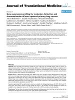
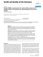
The state transition is defined as sho wn in Figure 1.
To jump up to the higher state (for example, from S
2
to
S
3
) or stay in its current state means that the burst
(probably caused by the arrival of a new I-frame) occurs.
Hence, t he mechanism must provide an extra duration
for clearing the occurred burst.
For jumping down from state S
2
and S
3
(probably
caused by a small B-frame or P-frame), the next state
becomes S
1
, because the burst has been served and the
system should provide only the minimum amount
TXOP duration. Nonetheless, to jump down from the
highest state, S
4
, for all occurrence events, the next state
becomes state S
3
. State S
4
implies that there are a high
number of packets in the queue (pro bab ly caused by an
I-frame), which are being serviced in this SI. Thus, the
system should remain in state S
4
.Otherwise,there
should be only few left-over packets in the queue wait-
ing for the service, which causes the fe edback q
i
to
become a low value. However, there might be new arri-
val packets, such as following B-or P-frames after the I -
frame. The mechanism, therefore, plans to clear up all
waiting packets plus new arrivals by remaining in state
S
3
for overprovisioning.
TXOP Calculation
Normally, the number of packet calculation, N
i
(as
shown in Equation 1), is rounded up to its ceiling value.
In t he proposed mechanism, the TXOP duration is allo-
cated with an extra duration. If the regular N
i
has been
used, the TXOP duration will become much more
overprovisioning.
Hence, the n ew calculation for the number of p ackets
hasbeenproposedbyusingthefloorvalueinsteadof
the ceiling value. Let
N
i
be a new calculated number of
packets for flow i. Eq uations 5 and 6 show the new cal-
culation o f the number of packets and TXOP duration
used in the proposed mechanism at state S
j
, respectively.
N
i
=
γ
j
¯
q
i
L
i
(5)
T
XOP
i
=max
N
i
× L
i
R
data
+ O,
M
R
data
+ O
(6)
Mechanism type 2 (ATMV2)
For some types of video transmi ssion, the I-frame might
be very huge (upto 20 packets, 1,024 bytes per packet).
Table 1 Event table of flow i for ATMV1.
Event Comparison condition
e
1
q
i
≤ δ
1
¯
q
i
e
2
δ
1
¯
q
i
< q
i
≤ δ
2
¯
q
i
e
3
δ
2
¯
q
i
< q
i
≤ δ
3
¯
q
i
e
4
q
i
>δ
3
¯
q
i
S
1
S
2
S
3
S
4
e
2
e
3
e
4
e
4
e
4
e
3
e
1
e
3
e
4
e
2
e
1
,e
2
e
1
,e
2
,e
3
e
1
Figure 1 Finite state machine for ATMV1.
Jansang and Phonphoem EURASIP Journal on Wireless Communications
and Networking 2011, 2011:158
/>Page 4 of 16
If all pieces (packets) of the I-frame cannot arrive at the
destination in time, then the particular frame will be
dropped. Moreover, the following B- and P-frames are
also useless if the leading I-frame has been dropped.
From ATMV1, the allowed maximum burst size is
limited to 3 times (g
4
=3)ofthe
¯
q
i
defined in state S
4
.
To cope with such a high burst, one might think that
increas ing the g
4
value can help. Unfortunately, if t he q
i
is slightly higher than
δ
3
¯
q
i
, then the particular flow will
be granted w ith the high g
4
value, which causes low
overall system utilization and less number of accepted
flows.
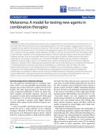
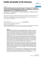
Therefore, another mechanism called ATMV2has
been proposed. A new state S
5
, along with the g
5
=4,
has been added to cope with such a high burst. How-
ever, the system should stay in S
5
for only a short period
and return to the normal state, S
1
, as soon as possible
due to the usage of high amount of resources. The
ATMV2 finite state machine is shown in Figure 2.
ATMV2 requires a new event called e
5
.Thee
4
and δ
4
are also modified by setting the δ
4
to 4. Table 2 shows
the new event table. The number of packets and TXOP
durati on for any state S
j
can be also calculated based on
Equations 5 and 6.
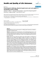
3.2 Implementation details
In the simulation, the proposed mechanism has been
implemented on QAP as shown in Figure 3. For each
SI,atthestartofHCCA(showninFigure4),QAP
starts the process by evaluating the next state S
j
according to the current state S
j’
and the event e
i
of the
particular flow i. Then, QAP polls each flow i with the
granted TXOP duration as calculated. During the poll-
ing period, the feedback queue size of flow i can be
recorded at QAP for generating the event e
i
for the next
SI. Once all flows have been polled, the contention-free
period is ended (the end HCCA, shown in Figure 4).
Then, QAP waits for the start of HCCA in the next SI
to continue the process.
The algorithm detail s of TXOP adjustment mechan-
ism have been shown in Table 3. The event e
i
can be
evaluated according to ATMV1andATMV2asshown
in Table 4 and 5, respectively.
From the Table 3, after the TXOP adjustment mechan-
ism for each flow has been performed (lin e 6-11), the
summation of TXOP requirements of all flows will then
be compared with the available resource. If the sum of
required durations is less than the available resource,
each flow will be granted as calculated. Otherwise, each
flow will receive only the committed TXOP duration as
specified in S
1
. The algorithm can be seen in line 13-17.
S
1
S
2
S
3
S
5
S
4
e
2
e
3
e
4
e
1
e
3
e
4
e
2
e
1
,e
2
,e
3
e
4
e
5
e
5
e
5
e
5
e
5
e
4
e
3
e
1
e
1
,e
2
e
1
,e
2
,e
3
,e
4
Figure 2 Finite state machine for ATMV2.
Table 2 Event table of flow i for ATMV2.
Event Comparison condition
e
1
q
i
≤ δ
1
¯
q
i
e
2
δ
1
¯
q
i
< q
i
≤ δ
2
¯
q
i
e
3
δ
2
¯
q
i
< q
i
≤ δ
3
¯
q
i
e
4
δ
3
¯
q
i
< q
i
≤ δ
4
¯
q
i
e
5
q
i
>δ
4
¯
q
i
Jansang and Phonphoem EURASIP Journal on Wireless Communications
and Networking 2011, 2011:158
/>Page 5 of 16
3.3 Computational complexity
In the proposed mechanism, shown in Table 3, the
operations at QAP can be divided into two major parts,
TXOP duration calculation part (line 6-11) and checking
for resource availability part (line 13-17). The first part
comp oses of four steps for a particular flow i: (1) evalu-
ate an event of the current flow, (2) evaluate a next
state, (3) calculate a granted TXOP duration, and (4)
Yes
No
start HCCA
end HCCA
SI
i
i
Figure 3 The mechanism work flow located at QAP.
Jansang and Phonphoem EURASIP Journal on Wireless Communications
and Networking 2011, 2011:158
/>Page 6 of 16
calculate the sum of granted TXOP durations. Each step
is a constant time, O(1). Let n be the number of active
flows in the polling list. Therefore, the computational
complexity for the first part is O(n). For checking
resource availability shown in the second part, if the
condition is valid (not enough resource), QAP will set
the TXOP duration for all flows. The complexity in thi s
part becomes O(n). Otherwise, the complexity is O(1).
Thus, the overall computational complexity of the pro-
posed mechanism becomes O(n).
4 Performance evaluation and discussion
In this section, the simulation has been described in
details. The proposed mechanism is evaluated by using
the EvalVid [13] framework. Various videos have been
tested for quality measurements.
4.1 Simulation setup
The network simulator (NS2 ) [14], version 2.29, with
IEEE 802.11e HCCA patch [15] is deployed. The HCCA
standard has b een enhanced by our proposed ATMV
mechanism as an extension. To evaluate the video qual-
ity, the E valvid framework is also patched. The admis-
sion control, for accepting any video flow, follows the
reference scheme.
The testing scenario is composed of one QAP and
cer tain number of QSTAs. All stations operate within a
basic service set, infrastructure mode, with the ideal
wireless channel assumption, as shown in Figure 5. To
concentrate on the HCCA evaluation, all stations oper-
ate only in the HCCA mode without the allocated
EDCA duration (the contention period, T
cp
= 0).
QAP acts as a sink video receiver, while all QSTAs are
video generators. Each QSTA will generate only one
traffic f low due to the limitation of the adopted HCCA
patch. However, for more traffic flows, QSTAs are
added as required. To make sure th at concurrent video
flows occur during the test, each QSTA randomly starts
the transmission uniformly within 0 and 3 s. The simu-
lation parameters are listed in Table 6.
In general working environment, both downlink and
uplink traffic can occur. For the downlink direction,
QAP knows all parameters related to the flow. The
queue size can be directly and easily obtained with t he
exact value before the TXOP duration adjustment. How-
ever, for the uplink dir ection, QAP can only retrieve the
queue size information for each flow by observing the
picky-backed queue size field in the data packet as a
feedback. T he received queue size information is not
accounted for new arrival packets during the current SI.
Therefore, to evaluate our mechanism based on the
end HCCA start HCCAstart HCCA
TXOP
1
TXOP
2
TXOP
i
···
SI
TXOP
1
TXOP
2
······
t
Figure 4 The start and end HCCA for each SI.
Table 3 TXOP adjustment based on state machine
1. PLIST[] ¬ Polling List
2. STATE[] ¬ Flow State List
3. Q[]¬ Feeback Queue Size List
4. TXOP
curr
[]¬ Current TXOP List
5. SUM
txop
¬ 0
6. for p in PLIST do
7. event ¬ getEvent(p, Q[])
8. STATE[p] ¬ evaluateNextState(p,STATE[],event)
9. TXOP
curr
[p] ¬ calculateTXOP(p,STATE[])
10. SUM
txop
¬ SUM
txop
+ TXOP
curr
[p]
11. end for
12.
13. if SUM
txop
>(SI - T
cp
) then
14. for p in PLIST do
15. TXOP
curr
[p] ¬ calculateTXOP(p,S
1
)
16. end for
17. end if
Table 4 getEvent(p,Q[]) for ATMV1
1. δ
1
¬ 1, δ
2
¬ 1.5, δ
3
¬ 2.5
2. event ¬ 0
3. q ¬ Q[p]
4. SI ¬ getSI()
5.
¯
q ← SI ∗ getMeanDataRate(p)
6. if
(q ≤ δ
1
¯
q)
then
7. event ¬ e
1
8. else if
(q ≤ δ
2
¯
q)
then
9. event ¬ e
2
10. else if
(q ≤ δ
3
¯
q)
then
11. event ¬ e
3
12. else
13. event ¬ e
4
14. end if
15. return event
Jansang and Phonphoem EURASIP Journal on Wireless Communications
and Networking 2011, 2011:158
/>Page 7 of 16
feedback information, only the uplink direction has been
tested.
4.2 Video traffic details
Five video clips have been selected from the open video
trace library [16] for testing. All video s are raw, uncom-
pressed, and encoded in 4:2:0 YUV format with video
resolution 352 × 288CIF. The selected videos can be
classified [17] into three categories: slight movement,
gentle walking, and rapid movement. The slight move-
ment is represented by Akiyo. Container and Foreman
represent the gentle walking category; while, Coastguard
and Highway re present the ra pid movement category.
All videos are 300 frames in length except the Highway
that contains 2000 frames. The snapshots of five videos
are displayed in Figure 6.
In our simulation, all video clips are encoded into
MPEG-4 format with target bit rate 256 Kbps, 30 fps,
GOP(9,3) by using the ffmpeg [18] version SVN-r23131.
Normally, an video frame (such as I-and P-frame) is
quite large compared to the MTU packet size in the
MAC layer. Hence, the fragmentation is required. In our
case, each video frame is fragmented into 1,024 byte
maximum packet size.
For example, the 300 frame of Akiyo composes of 34
I-frames, 199 B-frames, and 67 P-frames, fragmented
into 283, 199, and 79 packets, respectively. The average
packet sizes for I-, B-, and P-frames are 956, 179, and
624 bytes, respectively. The overall average packet size
(638 bytes) has been used as L
i
, nominal MSDU in the
requested TSPEC. T he details of o ther videos can be
seen in Table 7.
4.3 Video quality evaluation
To evaluate the system performance of the proposed
mechanism, mean packet delay, TXOP loss factor,and
channel occupancy are considered. The mean packet
delay measures the average duration of all packets trans-
mitted from a video s ender (QSTA) to a video receiver
(QAP). The TXOP loss factor is the ratio of unused
TXOP duration compared to the allocated TXOP dura-
tion assigned by QAP for each flow,
(
TXOP
allocated
−
TXOP
used
)/
TXOP
allocated
.The
channel occupancy indicates the system utilization by
measuring the reserved TXOP duration of all flows
compared to an SI.
For the objective video evaluation, PSNR (Peak Signal to
Noise Ratio ) has been used. The quality of t he video can
be measured by the amount of decreasing PSNR at the
receiver station compared to PSNR at the sender station.
Table 5 getEvent(p,Q[]) for ATMV2
1. δ
1
¬ 1, δ
2
¬ 1.5, δ
3
¬ 2.5, δ
4
¬ 4
2. event ¬ 0
3. q ¬ Q[p]
4. SI ¬ getSI()
5.
¯
q ← SI ∗ getMeanDataRate(p)
6. if
(q ≤ δ
1
¯
q)
then
7. event ¬ e
1
8. else if
(q ≤ δ
2
¯
q)
then
9. event ¬ e
2
10. else if
(q ≤ δ
3
¯
q)
then
11. event ¬ e
3
12. else if
(q ≤ δ
4
¯
q)
then
13. event ¬ e
4
14. else
15. event ¬ e
5
16. end if
17. return event
QAP
Video Receiver
QSTA1
QSTA2
Video Sender #1
Video Sender #2
Video Sender
··· ···
Figure 5 Configuration scenario in the simulation.
Table 6 Simulation parameters.
Parameter Value
MAC protocol IEEE 802.11b/e
SIFS 10 μs
PIFS 30 μs
DIFS 50 μs
Slot time 20 μs
PHY header 192 bits
MAC header 288 bits
ACK size 304 bits
Data rate 11 Mbps
Basic rate 1 Mbps
Antenna Omnidirectional antenna
Mobility None
IFQ (interface queue) 50 packets
SI 50 ms
Jansang and Phonphoem EURASIP Journal on Wireless Communications
and Networking 2011, 2011:158
/>Page 8 of 16
While MOS (mean opinion score) is one of the popular
metrics [19] for video quality measurement, MOS is repre-
sented by the s ubjective video evaluation, obt ained from
the perception of trained viewers, which is somehow
related to the PSNR value. T he relation between P SNR
and MOS can be found in [13] as shown in Table 8.
To measure PSNR and MOS value of a video clip, w e
adopt the EvalVid toolse t (used by many researchers
such as [20-24]). H owever, the toolset only provides the
video measurement method.
To integrate the toolset with NS2, a video sender and
receiver modules, called MyUDP, located at the sender
and receiver stations are added. The s ender module,
acts as a traffic generator, reads a video trace file from
EvalVid toolset and generates a stream of corresponding
packets for transmission. Then, packets will be sent out
in the NS2 simulation environment. Once packets arrive
at the receiver station, the receiver module records their
packet time stamps and g enerates the video trace file to
EvalVid toolset for evaluation. The implementation
details can be found at [25].
4.4 Experimental results
To demonstrate t he behavior of each mechanism, the
allocation and actual usage of TXOP duration in each SI
have been shown in Figure 7. The proposed mechan-
isms, ATMV1andATMV2, are compared with both
basic mecha nism (defined in the standard) and ARROW
mechanism for a same video clip, e.g., Akiyo.
From Figu re 7a, the basic mechanism allocates a con-
stant TXOP duration according to the mean data rate
specified in the TSPEC, which might not be enough to
serve all waiting packets in queue. Thus, the actual
usage is still limited by the fixed allocation. In contrast
with ARROW, ATMV1, and AT MV2, allocated TXOP
durations are varied based on the feedback queue size
information. Hence, the traffic stream can be served at
the higher data rate according to an allowed certain
burst duration as s hown in Figure 7b-d. The minimum
TXOP allocation of ARROW is a duration for transmit-
ting one packet with the maximum MSDU size, while
ATMV1andATMV2 allow transmission for a duration
of
γ
1
¯
q
i
. The allocation behavior of each mechanism
causes the differen ce in TXOP loss factor value, details
are shown in Figure 8.
System performance
The mean packet delay, TXOP loss factor, and chan nel
occupancy are averaged from 20 simulat ion replications
for each experiment.
(a) Akiyo (b) Container (c) Foreman
(d) Coastguard (e) Highway
Figure 6 Selected videos for performance evaluation.
Table 7 The details of tested video clips.
Video Number of packets Total
(avg.packet size in byte) (avg.packet size in byte)
IBP
Akiyo 283 199 79 561
(956) (179) (624) (638)
Container 276 208 104 588
(960) (168) (600) (616)
Foreman 164 227 132 523
(893) (458) (760) (671)
Coastguard 179 224 129 532
(956) (400) (848) (696)
Highway 1,126 1,373 701 3,200
(927) (487) (690) (687)
Table 8 PSNR to MOS conversion.
PSNR[dB] MOS
>37 5 (excellent)
31-37 4 (good)
25-31 3 (fair)
20-25 2 (poor)
<20 1 (bad)
Jansang and Phonphoem EURASIP Journal on Wireless Communications
and Networking 2011, 2011:158
/>Page 9 of 16
Figur e 8 shows the mean packet delay and TXOP loss
factor. Howeve r, the mean p acket delay of all videos for
basic mechanism is not displayed in the graph due to
their high delays (>200 ms). If all concurrent flows are
fully served (enough resource), e.g., 7 concurrent flows
for Akiyo, the mean packet delay is quite constant.
Once the demand is o ver the available resource, the
mean packet delay starts to increase.
For Akiyo (Figure 8a), representing the slight move-
ment video category, the mean packet delay for the
ATMV1andATMV2 are slightly higher than ARROW,
but both TXOP loss factors are lower than ARROW (6%
for ATMV1and8%forATMV2). ARROW mechanism,
with high overprov ision allocation, might cause the high
TXOP loss factor for slight change in content among
video frames.
For Container (Figure 8b), representing the gentle
walking movement video category, the mean packet
delay of ARROW is better than both proposed mechan-
isms. However, t he TXOP loss factor of ARROW is still
higher but closed to ATMV1andATMV2, because the
change of fr ame content has been increased, compared
with Akiyo.
The results of Foreman (Figure 8c) is quite interesting.
Even though it has been classified a s a gentle walking
movement, it contains two major scenes: the still shot
with slight movement scene and a panning high move-
ment scene. With ATMV1 allocation mechanism, the
video cannot be well served. However, ATMV2and
ARROW mechanisms provide enough overprovision to
support t he traffic with closed TXOP loss factor (2-3%
differences).
For Coastguard and Highway (Figure 8d, e), represent-
ing the rapid movement video category, the mean
packet delay of ATMV1 is higher than others. However,
ATMV2 shows the lowest values for both mean packet
delay and TXOP loss factor.
The channel occupancy for all video clips increases as
the number of concurrent flows increases, as shown in
Figure 9. All mechanisms reveal no significant difference
in the channel occupancy metric.
For different traffic conditions, both proposed
mechanisms grant the TXOP duration based on the
feedback queue size of a flow. In case of high or burst
traffic, QAP will allocate TXOP duration as high
amount as request, bounded by the coef ficient facto r of
the evalua ted state, such as state S
4
in ATMV1 or state
S
5
in ATMV 2. However, in lig ht traffic condition, if t he
required feedback queue size is less than the committed
average queue size
(
¯
q
i
)
, QAP grants the TXOP duration
as the boundary of the state S
1
. The amount of granted
duration is only a little over provision from the com-
mitted traffic specification (TSPEC) of the particular
flow, which causes low TXOP loss factor.
Video quality
The video quality has been evaluated by the PSNR and
MOS values extracted from EvalVid toolset. Both values
Figure 7 TXOP allocation and usage of Akiyo.
Jansang and Phonphoem EURASIP Journal on Wireless Communications
and Networking 2011, 2011:158
/>Page 10 of 16
Figure 8 The mean packet delay and TXOP loss factor.
Jansang and Phonphoem EURASIP Journal on Wireless Communications
and Networking 2011, 2011:158
/>Page 11 of 16
are calculated at the sender station (e.g., QSTA) as
details in Section 4.3 and be kept as reference values.
Let PSNR
S
and MOS
S
be the PSNR and MOS at the
sender station, while PSNR
R
and MOS
R
be the PSNR
and MOS at the receiver station. Figure 10 shows PSNR
and its correspondent MOS for all video clips from the
firsttolastframe.TheexpectedvaluesforPSNRand
MOS are displayed in Table 9.
Once the video clip has been received at the receiver
station, the expected PSNR and MOS values are recalcu-
lated as PSNR
R
and MOS
R
.Inthesimulation,atthe
receiver station, the video playout buffer is set to 400
ms according to the ITU-T G.1010 [26], the worst case
of one-way delay for video medium. If received packets
for the corresponding frames arrive after 400 ms, those
packets will not be accounted for the particular video
frame reconstruction. Then, PSNR
R
and MOS
R
are com-
pared to previous reference values, PSNR
S
and MOS
S
.
The equality of the PSNR and MOS values means that
the video quality has been preserved. Howe ver, in real
situation, PSNR
R
and MOS
R
are normally less than
PSNR
S
and MOS
S
due to loss or delayed packets, which
might cause the video quality to be degr aded. Figure 11
shows the expected PSNR
R
and MOS
R
values of all
received flows, which can be compared with PSNR
S
and
MOS
S
, shown in Table 9.
For Akiyo (Figure 11a), ATMV1, ATMV2, and
ARROW mechanisms reveal the same PSNR (PSNR
R
=
PSNR
S
) and MOS (MOS
R
=MOS
S
) values for the case
of less t han or equal to 7 conc urrent flows. For 8 flows,
ATMV1 is the only mechanism that can maintain the
same quality. Normally, for more than 7 flows, the
PSNR
R
and MOS
R
of all mechanisms (except the basic
mechanism) start to degrade due to the not enough
available resource. Note that, for the basic mechanism,
the PSNR
R
and M OS
R
areconstantatalowvalue(low
quality) due to its non-adaptive characteristic.
For Container (Figure 11b), ATMV2andARROW
mechanisms show the same values as references for up
to 7 concurrent flows. In case of ATMV1, the video
quality is quite the same with small degradation of 1 dB
for PSNR
R
and 0.17 for MOS
R
values compared to
ATMV2andARROW. For For eman (Figure 11c),
ATMV2andARROW mechanisms show the same
values as references for up to 5 concurrent flows; while
ATMV1 degraded with 5 dB in PSNR
R
,and0.8in
MOS
R
.
For Coastguard (Figure 11d), ATMV2andARROW
mechanisms show the same values as references for up
to 5 concurrent flows. T he 4 dB in PSNR
R
and 0.87
MOS
R
are shown for the case of ATMV1. For Highway
(Figure 11e), both values are as same as references for
up to 7 concurrent flows. ATMV1 has been degraded
with the values closed to the basic mechanism.
Figure 9 Channel occupancy.
Jansang and Phonphoem EURASIP Journal on Wireless Communications
and Networking 2011, 2011:158
/>Page 12 of 16
For real implementation, videos sent from different
QS-TAs at the same time may belong to different cate-
gories. Moreover, within the same QSTA, different flows
(sessions) might also be classified into different cate-
gories. In case of known priori video category, QAP
may be implemented by adding selective mechanism to
call appropriate functions (i.e., “getEvent” and “evaluate-
NextState” from Table 3, line 7-8); for example, QAP
will select “getEvent ” (from Tab le 4) of the ATMV1
Table 9 The expected PSNR
S
and MOS
S
of video clips at
the sender station.
Video clip PSNR
S
[dB] MOS
S
Akiyo 40.13 ± 1.48 5.00 ± 0.00
Container 32.44 ± 3.17 3.69 ± 0.59
Foreman 29.78 ± 3.10 3.23 ± 0.53
Coastguard 27.68 ± 2.14 3.08 ± 0.33
Highway 35.83 ± 1.62 4.17 ± 0.39
Figure 10 PSNR
S
and MOS
S
of tested videos (at sender station).
Jansang and Phonphoem EURASIP Journal on Wireless Communications
and Networking 2011, 2011:158
/>Page 13 of 16
Figure 11 Expected PSNR
R
and MOS
R
of tested videos (at receiver station).
Jansang and Phonphoem EURASIP Journal on Wireless Communications
and Networking 2011, 2011:158
/>Page 14 of 16
once the slightly movement video flow is evaluated,
while “ getEvent” (from Table 5 ) of the ATMV2 will be
called if the rapid movement video session occurs. How-
ever, in case of unknown video category, QAP will select
a default mechanism (i.e., ATMV1) for serving that par-
ticular flow. If QAP finds that the m onitored flow falls
into the state S
4
for many consecutive SIs, it means that
the flow is high burst, which should be adjusted to
ATMV2. Theref ore, the proposed ATMV1andATMV2
mechanisms can be simultaneously implemented for ser-
ving each flow separately.
5 Conclusions
The feedback mec hanism called ATMV has been pro-
posed to support video transmission in IEEE 802.11e
HCCA at QAP by adjusting the TXOP duration. The
feedback is based on the queue size information in
QSTA. The mechanism aims for quick response to
serve the burst packets generated from the incoming
video frames. The adjustment algorithm follows the pro-
posed 4-state and 5-state finite state machines for
ATMV1andATMV2, respectively. Both proposed
mechanisms are compared with t he (standard) basic
mechanism and ARROW mechanism, tested by 5 video
clips cl assified into 3 video categories: the slight move-
ment, gentle walking movement, and rapid movement.
The results show that both proposed mechanisms,
including ARROW, outperform the basic mechanism in
terms of the system performance and video quality for
all video categories.
ATMV 1 is suitable for the slight movement video and
can support up to 8 concurrent flows. However, the
video quality has been degraded with other video
categories.
ATMV2andARROW are suitable for all video c ate-
gories with non-degradation quality and can sup port up
to 7, 5-6, and 5 concurrent flows for the slight move-
ment, gentle walking movement, and rapid movement,
respectively. However, the ATMV2 shows the best per-
formance in terms of mean packet delay and TXO P loss
factor for rapid movement category. For th e sl ight
movement, ATMV2 reveals better TXOP loss factor
with small hi gher delay (but still under 100 ms). Finally,
for the gentle walking category, TXOP loss factor for
both mechanisms are quite the same, While ATMV2
and ARROW take turn outperforming each other in
terms of mean packe t delay. Howeve r, the packet delay
of both mechanisms is less than 120 ms.
The summarization of proposed mechanis ms, ATMV1
and ATMV2, is shown in Table 10.
Note that the reference admission control process
admits each flow based on the mean TXOP duration,
which is not designed for the dynamic allocation.
Hence, for future work, the admission control process
needs to be modified for accounting the ATMV dynamic
mechanism behavior. Obviously, the number of accepted
flows of the modified admission control might be
slightly decreased, but the video q uality of accepted
video flows is highly preserved.
To better tuning the ATMV mechanism, the coeffi-
cient factor for bounding amount of allocated queue
size of each sta te in the finite state machine should be
dynamically adjusted according to the changing of major
scenes in the video. We foresee that system is able to
support unknown video categories or mixed contents in
one video clip.
In addition, the TX OP allocation mechanism located
at QAP should account for maint aining the quality of
Table 10 ATMV1 and ATVM2 summarization.
Mechanism properties ATMV1 ATMV2
Number of states 4-state finite state machine 5-state finite state machine
Video characteristic Burst arrival High burst arrival
Supported video categories Slight movement Gentle walking, Rapid movement
Coefficient factor for bounding the range of the particular event δ
1
=1 δ
1
=1
δ
2
= 1.5 δ
2
= 1.5
δ
3
= 2.5 δ
3
= 2.5
δ
4
=4
Coefficient factor for bounding the allocated queue size g
1
=1 g
1
=1
g
2
= 1.5 g
2
= 1.5
g
3
= 2.5 g
3
= 2.5
g
4
=3 g
4
=3
g
5
=4
Maximum granted TXOP duration for flow i
T
XOP
i
=
γ
4
¯
q
i
L
i
×L
i
R
data
+
O
T
XOP
i
=
γ
5
¯
q
i
L
i
×L
i
R
data
+
O
Computational complexity O(n), where n is a number of active flows in the polling list
Jansang and Phonphoem EURASIP Journal on Wireless Communications
and Networking 2011, 2011:158
/>Page 15 of 16
accepted flows that might be degraded by the noisy
channel environment.
Acknowledgements
This work has been supported by Computer Engineering Graduate School
Kasetsart University and Kasetsart University Research and Development
Institute (Ref. 5510520000/2555).
Competing interests
The authors declare that they have no competing interests.
Received: 6 April 2011 Accepted: 7 November 2011
Published: 7 November 2011
References
1. Wireless LAN Medium Access Control (MAC) and Physical Layer (PHY)
Specifications. IEEE Standard 802.11 (1999)
2. IEEE Std. 802.11e-2005, Part 11: wireless LAN medium access control (MAC)
and physical layer (PHY) specifications, amendment 8: medium access
control (MAC) quality of service enhancements (2005)
3. T Sikora, MPEG digital video-coding standards. Signal Process IEEE Mag.
14(5), 82–100 (1997). doi:10.1109/79.618010
4. ITU-T Recommendation G.711. Pulse code modulation (PCM) of voice
frequencies (1988)
5. ITU-T Recommendation G.718. Frame error robust narrowband and
wideband embedded variable bit-rate coding of speech and audio from 8-
32 Kb/s (2008)
6. P Ansel, Q Ni, T Turletti, FHCF: a simple and efficient scheduling scheme for
IEEE 802.11e wireless LAN. Mob Netw Appl. 11(3), 391–403 (2006).
doi:10.1007/s11036-006-5191-z
7. N Passas, D Skyrianoglou, P Mouziouras, Prioritized support of different
traffic classes in IEEE 802.11e wireless LANs. Comput Commun. 29(15),
2867–2880 (2006). doi:10.1016/j.comcom.2006.03.010
8. D Skyrianoglou, N Passas, A Salkintzis, ARROW: an efficient traffic scheduling
algorithm for IEEE 802.11e HCCA. IEEE Trans Wirel Commun. 5(12),
3558–3567 (2006)
9. SM Kim, YJ Cho, Channel time allocation scheme based on feedback
information in IEEE 802.11e wireless LANs. Comput Netw. 51(10), 2771–2787
(2007). doi:10.1016/j.comnet.2006.11.024
10. P Seeling, FH Fitzek, M Reisslein, Video Traces for Network Performance
Evaluation, (Springer, Berlin, 2006)
11. G Boggia, P Camarda, L Grieco, S Mascolo, Feedback-based control for
providing real-time services with the 802.11e MAC. IEEE/ACM Trans Netw.
15(2), 323–333 (2007)
12. A Jansang, A Phonphoem, B Paillassa, Analytical Model for Expected Packet
Delay Evaluation in IEEE 802.11e, in Proceedings of the 2009 WRI
International Conference on Communications and Mobile Computing, vol. 2.
IEEE Computer Society, Washington, pp. 344–348 (2009)
13. J Klaue, B Rathke, A Wolisz, EvalVid–a framework for video transmission and
quality evaluation. In Proceeding of the 13th International Conference on
Modelling Techniques and Tools for Computer Performance Evaluation,
Urbana, IL, USA 255–272 (2003)
14. The Network Simulator–ns-2 (1999)
15. C Cicconetti, L Lenzini, E Mingozzi, G Stea, A Software Architecture for
Simulating IEEE 802.11e HCCA. In Proceedings of the 3rd International
Workshop on Internet Performance, Simulation, Monitoring and
Measurement, Warsaw, Poland 97–104 (2005)
16. YUV video sequences (CIF) />html
17. A Khan, L Sun, EC Ifeachor, Content-based video quality prediction for
MPEG4 video streaming over wireless networks. J Multimed. 4(4), 228–239
(2009)
18. FFmpeg (2008)
19. ITU-T Recommendation BT.500-11. Methodology for the subjective
assessment of the quality of television pictures (2002)
20. M Abdel-Hady, R Ward, A framework for evaluating video transmission over
wireless ad hoc networks. In Proceedings of IEEE Pacific Rim Conference on
Communications, Computers and Signal Processing 2007 (PacRim2007),
Victoria, B.C., Canada 78–81
21. M Choi, M Samokhina, K Moklyuk, S Choi, J Heo, SJ Oh, VPAL: video packet
adaptation layer for reliable video multicast over IEEE 802.11n WLAN.
Comput Commun. 33(18), 2271–2281 (2010). doi:10.1016/j.
comcom.2010.06.018
22. CH Ke, N Chilamkurti, A new framework for MPEG video delivery over
heterogeneous networks. Comput Commun. 31(11), 2656–2668 (2008).
doi:10.1016/j.comcom.2008.02.029
23. A Lie, J Klaue, Evalvid-RA: trace driven simulation of rate adaptive MPEG-4
VBR video. Multimed Syst. 14,33–50 (2008). doi:10.1007/s00530-007-0110-0
24. M Venkataraman, M Chatterjee, S Chattopadhyay, Evaluating Quality of
Experience for Streaming Video in Real Time. In Proceedings of IEEE Global
Telecommunications Conference 2009 (GLOBECOM2009), Honolulu, Hawaii,
USA 1–6
25. CH Ke, CK Shieh, WS Hwang, A Ziviani, An evaluation framework for more
realistic simulations of MPEG video transmission. J Inf Sci Eng. 24(2),
425–440 (2008)
26. ITU-T Recommendation G.1010. End-user multimedia QoS categories (2001)
doi:10.1186/1687-1499-2011-158
Cite this article as: Jansang and Phonphoem: Adjustable TXOP
mechanism for supporting video transmission in IEEE 802.11e HCCA.
EURASIP Journal on Wireless Communications
and Networking 2011 2011:158.
Submit your manuscript to a
journal and benefi t from:
7 Convenient online submission
7 Rigorous peer review
7 Immediate publication on acceptance
7 Open access: articles freely available online
7 High visibility within the fi eld
7 Retaining the copyright to your article
Submit your next manuscript at 7 springeropen.com
Jansang and Phonphoem EURASIP Journal on Wireless Communications
and Networking 2011, 2011:158
/>Page 16 of 16