Báo cáo hóa học: " Fuzzy-assisted social-based routing for urban vehicular environments" pptx
Bạn đang xem bản rút gọn của tài liệu. Xem và tải ngay bản đầy đủ của tài liệu tại đây (4.99 MB, 15 trang )
RESEARCH Open Access
Fuzzy-assisted social-based routing for urban
vehicular environments
Rashid Hafeez Khokhar
1*
, Rafidah Md Noor
1
, Kayhan Zrar Ghafoor
2
, Chih-Heng Ke
3
and Md Asri Ngadi
2
Abstract
In the autonomous environment of Vehicular Ad hoc NETwork (VANET), vehicles randomly move with high speed
and rely on each other for successful data transmission process. The routing can be difficult or impossible to
predict in such intermittent vehicles connectivity and highly dynamic topology. The existing routing solutions do
not consider the knowledge that behaviour patterns exist in real-time urban vehicular networks. In this article, we
propose a fuzzy-assisted social-based routing (FAST) protocol that takes the advantage of social behaviour of
humans on the road to make optimal and secure routing decisions. FAST uses prior global knowledge of real-time
vehicular traffic for packet routing from the source to the destination. In FAST, fuzzy inference system leverages
friendship mechanism to make critical decisions at intersections which is based on prior global knowledge of real-
time vehicular traffic information. The simulation results in urban vehicular environment for with and without
obstacles scenario show that the FAST performs best in terms of packet delivery ratio with upto 32% increase,
average delay 80% decrease, and hops count 50% decrease compared to the state of the art VANET routing
solutions.
1 Introduction
Recently, the social-based networks have been built to
bring different groups of people within range for poten-
tial communication. Such social-based networks are not
only used to connect the computers for global commu-
nications network but it can also be used to connect
vehicles in urban environments. Social-based routing in
Vehicular Ad hoc NETwork (VANET) is attracted the
attention of research community where the traffic infor-
mation that behaviour patterns exist allow us to make
better routing decisions. VANET provides the ability for
vehicles to communicate wirelessly among nearby vehi-
cles and road-side wireless sen sors to transfer informa-
tion for safe driving, dynamic route planning, mobile
sensing and in-car entertainment. Existing VANETs
routing protocols, for example, GPSR [1], GPCR [2],
LOUVRE [3], geographical greedy traffic-aware routing
(GyTAR) [4], RBVT-R [5], GeoCross [6] and ReTARS
[7], only work well in cooperati ve urban environments.
Currently, the vehicles have short radio communication
range from 3 00 to 1000 m based on IEEE 802.11p, and
VANET routing protocols need more vehicles to trans-
fer data to make one-one communications across wider
area. Consequently, it is necessary to develop efficient
routing protocols for growing vehicular networks.
Geographical routing pro tocols [1,2,4,8-1 1] are the
well-suited protocols for VANETs environments. These
protoc ols use Global Positioning System (GPS) to locate
nodes on the map instead of establishing routes to for-
ward data packets from source to the destination
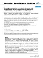
through interme diate nodes (neighbors). Figure 1a illus-
trates the routing strategy in these routing protocols in
ideal urban scenario with moderate, low or high mobi-
lity. The source node S first transmits the message to its
neighbor nodes using greedy or geographi cal forwarding
method in the street and perimeter probing at intersec-
tions. The message has been reached at intersection I
2
through route R
1
to R
2
where the decision-making node
N takes an important decision. The node N selects
route R
4
and finally reaches at destination node D
through R
5
.However,Figure1bdepictsthetwopro-
blems arise when these protocols are implemented on
real-world urban traffic scenario. First, it might be possi-
ble that there is no node at intersection I
2
within the
period of Time-to-Live (TTL) to make an important
decision. In this case, the message is forwarde d to ne xt
* Correspondence:
1
Faculty of Computer Science and Information Technology, University of
Malaya, 50603 Lembah Pantai, Kuala Lumpur, Malaysia
Full list of author information is available at the end of the article
Khokhar et al. EURASIP Journal on Wireless Communications and Networking 2011, 2011:178
/>© 2011 Khokhar et al; licensee Springer. This is an Open Access article distributed under the terms of the Creative Commons
Attribution L icense ( which permits unrestricted use, distribution, and reprodu ction in
any me dium, provided the original work is properly cited.
available node away from the intersection. Second, if
there is no vehicle on next routes, R
4
and R
6
, it can
cause unnecessary traffic overhead in the network and
longer delays for packets.
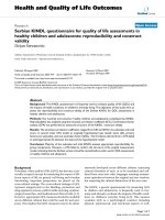
Another major problem in VANET routing protocols
is the dead-end roads that may cause many data packets
dropped, failure notification increases significantly, low
delivery ratios and fail to find shortest path. As illu-
strated in Figure 2, in most of the existing geographical
routing protocols the message forwards to nodes A, B
and C on a dead-end road which is the shortest path
from S to D. However, the message should follow the
dotted path as depicted in Figure 2. Greedy distributed
spanning tree routing (GDSTR) [12] proposed to find
shorter routes and generates less maintenanc e traffic if
greedy forwarding fails at the dead-end roads. GDSTR
creates and maintains hull trees to guide packets around
dead-end roads instead of usi ng planarization algorithm.
The simulation results have shown that GDSTR incurs
significantly lower overhead than protocol proposed in
[13]. A geo-proactive overlay routing called Landmark
Overlays for Urban Vehicular Routing Environments
(LOUVRE) [3] proposed to create an overlay links on
top of an urban topology. In LOUVRE, the nodes at
intersections are defined as landmark and the overlay
links are only possible if there is enough traffic density
between intersections. LOUVRE’s guaranteed multi-hop
routing is a suitable way to avoid dead-end roads. Jerbi
et al. [4] also proposed an intersection-based Greedy
Traffic- Aware Routing (GyTAR) protocol to find best
routes in urban environments. GyTAR creates routes
from source to destination based on sequence of con-
nected intersections. Two parameters including change
in vehicular t raffic information and the remaining dis-
tance from the destination are used to define a best
route. GyTAR also used an improved greedy forwarding
mechanism to forward data packet on the road seg-
ments. However, if there is no node at intersection, then
the packet cannot be forwarded and the performance of
LOUVRE and GyTAR affects as data packet dropped
and higher end-to-end delay. In another attempt,
Nzouonta et al. [5] proposed a reactive-based VANET
routing protocol called Road-Based using Vehicular
Traffic information-Reactive (RBVT-R), which creates
paths containing the successions of road intersections
with high probability and net work connectivity using
real-time vehicular traffic information. RBVT-R works
well in cooperative environment. However, they did not
considered anonymity issues during packet routing in
harsh vehicular network. In addition, static weights used
in RBVT-R cannot implement on real VANET urban
environment where network and traffic conditions dyna-
mically change.
In this article, we propose a FAST protocol to make
dynamic routes based on pr ior global knowledge using
(
a
)
Routes established in ideal cit y scenario
(
b
)
Routes failure in real-world city scenario
Figure 1 Routing strategy in existing VANET routing protocols without prior global knowledge.
Figure 2 Dea d-end roads can cause unnecessary overhead in
VANET.
Khokhar et al. EURASIP Journal on Wireless Communications and Networking 2011, 2011:178
/>Page 2 of 15
friendship mechanism. Instead of simply forwarding the
message to next available node towards destination like
in existing VANET routing protocols, we use more reli-
able approach with the help of social relations of vehi-
cles for optimal routing. The route message is
forwarded to next available node in streets if and only if
the intersection is far away from the node. In FAST, the
packet career node at intersection plays a key role to
selectthebestnextroadsegmentsandleveragesfuzzy
inferencesystemtomakereliableandsecurerouting
towards destination. The rest of the article is organized
as follows. Section 2 presents the proposed FAST proto-
col with examples from urban environment. In Section
3, we evaluate the performance of FAST by comparing
with some existing VANET routing protocols and the
article concludes with some future studies in Section 4.
2 Proposed fuzzy-assisted social-based routing
(FAST) protocol
We propose the FAST protocol that creates routes
dynamically for optimal routing in urban vehicular
environments. In FAST, the prior global knowledge of
rea l-time vehicular traffic is used to create routes dyna-
mically. The basic idea behind FAST is that first source
node broadcasts a short message with secure ID to the
neighbor nodes. Source node determines the types of
nodes when it confirms this node in the list of friends
or friends-of-friends. The nodes that are not in the
friends list w ill automatically be discarded. The source
nodemayhavemorethanonefriend,inthatcase,a
node which is closer to destination forwards the mes-
sage to next available node. But, if there is no next node
available at intersection to forward the data packet then
the current node in the street will hold the message if
and only if it can reach at intersection before TTL
expires, otherwise the message is forwarded to next
available node in the same street. We compare TTL
with the time a node takes to reach at intersection. The
time a node takes to reach at intersection is determined
as time = distance/speed. If the node can reach at inter-
section before TTL expires, this node becomes a deci-
sion-making node where it uses prior global knowledge
of real-time vehicular traffic to forward message to the
best suitable route towards destination. The decision-
making node uses traffic-density information based on
friends, friends-of-friends, and non-friends information
on each road segment and implement fuzzy inference
system to determine best route to wards destination. In
the following sections, we explain the steps involved in
the design of FAST protocol.
2.1 Friendship mechanism
The prior global knowledge of real-tim e traffic is deter-
mined by the node-density information in urban
environment. As illustrated in Section 1, the importance
of prior global knowledge and how the existing routing
protocols are fail to find next hop if there are not
enough nodes on next road segments. We use this
information to propose a friendship mechanism that will
speed up the route creation process of trusted route
towards destination. The real-time traffic information is
divided into three classes of mutual relationships such
as friends, friends-of-friends and non-friends. The
friendship mechanism is not proposed to design a fully
operational intrusion detection system (IDS) for vehicu-
lar networks. The purpose is to show that how the
social relationships between vehicles can be used for sig-
nificance performance of VANET routing protocols. We
have implemented o nly simple operational misuse and
anomaly detection engines based on existing works in
[14,15]. We have assumed that a pair of direct friends
or friends-of-friends who have mutual trust with each
other can communicate. The performance of friendship
mechanism in highly dynamic VANET routing protocol
is reduced, if each possible security relationship fully
owned by any two vehicles. It requires a lot of efforts if
each vehicle checks the secure relationship with other
vehicles. The proposed friendship mechanism is simple
yet efficient in the sense of exchange data packets with
other trusted vehicles.
We have considered three types of relationships
including direct friends, indirect friends (friends-of-
friends) and non-friends. The vehicles are used by
humans and their behaviours are based on social net-
work. In direct friendship, the vehicles may establish
relations using persona l judgement in daily life experi-
ences. As illustrated in Figure 3, the nodes can start
establish mutual relation in office and can be later direct
frien ds using Facebook, Twitter, Google+, LinkedIn , etc.
The nodes can also establish their relations on some
other places such as residential area, playground, shop-
ping mall, etc. On the other hand, indirect friendship is
based on the good reputation of other vehicles. There
are some advantages of these types of friendship in
terms of security, packet delivery ratio (PDR) and aver-
age delay. Most of existing security solutions are asso-
ciated with the authentication mechanisms, which
usually require expensive cryptography and an assump-
tion of a central authority. In addition, almost all of the
existing works lac k one important feature, which is no
collaborative effort among nodes to create a trusted
vehicular community. The creation of a trusted vehicu-
lar network is important to ensure an efficient Intelli-
gent Transportation System (ITS).
Furthermore, in trusted vehicular networks, the data
packets can be forwarded to friends and friends-of-
friends without any detailed security check for high PDR
and lower average delay. However, the average delay
Khokhar et al. EURASIP Journal on Wireless Communications and Networking 2011, 2011:178
/>Page 3 of 15
may increase if there is le ss number of direct or indirect
friends on the road. Although, the non-friends vehicles
cannotdirectlybeaddedinthelistoffriendsand
friends-of-friends. The new node can join the network
after establishing the mutual trust with friends or
friends-of-friends. There are two possible methods to
create a new set of friend nodes including real-world
experience and reputation of new node. Initial trust
based on a real-world friendship is more relevant than
that established based on nodes’ experience s at the early
stages of the proposed framework implementation. This
is because in such situation, each node is very unlikely
to have sufficient knowledge/experi ence about other
nodes, thus will not be able to rate other nodes’ reputa-
tions. Initial t rust based on reputation is more suitable
at the later stages when sufficient experiences have been
gathered. Perhaps the combination of the two methods
could result in a better performance. However, for sim-
plicity, only initial trust based on a real-world friendship
is implemented in the experiment to sho w how a
trusted community could be created in vehicular urban
environments. The direct friendships will be exchanged
between trusted friends to create a new set of friend
nodes, namely indirect friends (friends-of-friends ). How-
ever , if a node does not want to join social network will
be considered as non-friends node.
2.2 Design of fuzzy logic decision making system
It has discussed in Section1 that the vehicles move on
the roads with high speed in VANET and node-density
information frequently change from sparse to dense and
vice versa. Optimal decision plays an important role for
efficient data packet forwarding in highly dynamic
VANET environments. Artificial intelligence techniques
such as fuzzy logic perform well in classification and
decision-making systems [16,17]. We have used the
fuzzy logic system to make better decision at intersec-
tion for meaningful performance of the proposed FAST
protoc ol. The design of fuzzy logic decision-making sys-
tem consists of input membership functions and a set of
fuzzyrules.Thebasicideaistakenfromhumanbrain,
which simulates the interpretation of uncertain sensory
information [18]. In this study, it is applied on number
of friends, friends-of-friends, and non-friends which is
based on efficient arrangement of metrics (percentages
of friends, friends-of-friends and non-friends). In this
case, the packet carrier node does not know which path
is more efficient and secure (based on the rate of
friends) for the significance routing. Thus, the fuzzy
logic decisi on-making system offers an efficient solution
for this type of uncertain situation.
Figure 4 shows the steps involved in the design of
fuzzy logic decision-making system such as fuzzification
of input & output, fuzzy inference engine, and defuzzifi-
cation. Firstly, the input and output variables and their
membership functions are determined. Secondly , impor-
tant step is to define the fuzzy rules based on input and
output variables. This is followed by a group of rules
used to represent infere nce engine (knowledge base) for
articulating the control ac tion in linguistic form. The
following sections explain the input parameters used in
fuzzy inference system.
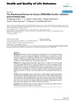
2.2.1 Fuzzification of inputs and outputs
Three input pa rameters are fuzzified including friends,
friends-of-friends, and non-friends as illustrated in Fig-
ure 5. The membership functions namely Sparse, Med-
ium and Dense areusedtorepresentthetrafficdensity
of friends, friends-of-friends,andnon-friends.Theselec-
tion of friends, friends-of-friends,andnon-friends mem-
bership functions can be derived based on experience as
well as trial-and-error of the application requirement,
thus, the range should be betwee n 0 a nd 1. The actual
reason to select this range is that a node might not have
same list of friends 0 or all nodes have friends list 1 in
the same path to the specified destination. When nodes
are establishing routes, the values of friends may vary
Figure 3 Social relation establishment between vehicles based on personal experiences.
Khokhar et al. EURASIP Journal on Wireless Communications and Networking 2011, 2011:178
/>Page 4 of 15
from minimum to maximum. So, the friendship value is
selected in reply to the percentage variation intelligent ly
integrated with the status of the nodes.
The output fuzzy cost is configured to a range
between 0 and 1; the greater this value, the m ore effi-
cient and optimal route will be. We have also used com-
putationally efficient triangular functions as membership
functions. The efficient design of membership function
has a positive impact on the performance of fuzzy deci-
sion-making process.
2.2.2 Fuzzy inference engine
In this step, we develop a set of rules using expert
knowle dge about meaningful performance of FAST pro-
tocol. The knowledge-based fuzzy rules are designed to
integrate the inputs and outputs variables which are
based on careful understanding of traffic patterns of
vehicular urban networks. We have defined 27 fuzzy
rules to design fuzzy inference decision-making system,
as shown in Table 1. Each rule consists of a IF part, a
logical connection and a THEN part. The IF conditions
Figure 4 Fuzzy logic components (fuzzification, inference engine, and defuzzification) to rank available paths.
(a) Input variable friends (b) Input variable friends-of-
friends
(c) Input variable non-friends
(
d
)
Output variable fuzzy cost
Figure 5 Fuzzification of three input variables (friends, friends-of-friends, and non-friends) and output variable (fuzzy cost).
Khokhar et al. EURASIP Journal on Wireless Communications and Networking 2011, 2011:178
/>Page 5 of 15
are built using predicates, and a logical connection is
used to connect antecedent and consequent parts,
whereas the THEN statement gives a degree of member-
ship function that befits the fuzzy variables involved. We
have designed fuzzy rules to give highest rank to the
route which has dense number of friends and friends-of-
friends. Thus, our FAST favours secure and fully con-
nected route towards packet’s destination. For instance,
in the case where F is 0.842 and FF is 0.137 and NF is
0.103, then FCost is 0.893. The path has this fuzzy cost
because of its high rate of friends and the sparse distri-
bution of non-friend vehicles. It means that our fuzzy
inferenc e system uses a trade-off decision between para-
meters (friends, f riends-of-friends, and non-friends) to
adaptively tune the cost of each path to the specified
destination. In addition, Figures 6 and 7 depi ct the rela-
tion between input and output variables. The t rend
shows that the value of output fuzzy cost increases
when the value of F and FF are increasing. Thus, our
fuzzy inference system could increase fuzzy cost as
number of friends per route increases.
2.2.3 Defuzzification
In defuzzification step, a crisp value is extracted from
fuzzy set. For this purpose, the centroid of area strategy
is taken for defuzzification in our fuzzy inference deci-
sion- making system . The defuzzifier process is based on
the following equation 1:
R =
All Rules
x
i
× β(x
i
)
All R
u
l
es
β(x
i
)
(1)
where R shows the degree of decision making, x
i
is the
fuzzy variable and b(x
i
) is its membership function.
2.3 Route discovery process
In FAST, a route discovery (RD) process is initiated
when a source node needs to determine a route for des-
tination node, control alg orithm diagram of FAST
Table 1 Knowledge structure based on fuzzy rules
IF THEN IF THEN
Rule F* FF* NF* FCost* Rule F FF NF FCost
1 Sparse Sparse Sparse VLow 15 Medium Medium Dense Low
2 Sparse Sparse Medium Low 16 Medium Dense Sparse High
3 Sparse Sparse Dense VLow 17 Medium Dense Medium High
4 Sparse Medium Sparse Low 18 Medium Dense Dense Medium
5 Sparse Medium Medium Low 19 Dense Sparse Sparse VHigh
6 Sparse Medium Dense Low 20 Dense Sparse Medium Medium
7 Sparse Dense Sparse Medium 21 Dense Sparse Dense Medium
8 Sparse Dense Medium Medium 22 Dense Medium Dense High
9 Sparse Dense Dense Low 23 Dense Medium Medium High
10 Medium Sparse Sparse Medium 24 Dense Medium Sparse VHigh
11 Medium Sparse Medium Medium 25 Dense Dense Sparse VHigh
12 Medium Sparse Dense Low 26 Dense Dense Medium High
13 Medium Medium Sparse High 27 Dense Dense Dense High
14 Medium Medium Medium High
F, friends; *FF, friends-of-friends; *NF, non-friends; *FCost, fuzzy-cost.
Figure 6 Correlation between input variables (friends and non-friends) and output (fuzzy-cost).
Khokhar et al. EURASIP Journal on Wireless Communications and Networking 2011, 2011:178
/>Page 6 of 15
protocol is illustrated in Figure 8. The source node cre-
ates a RD packet and the header of RD packet includes
the address of source node, address and location of des-
tination node, intersection ID, road segment ID, neigh-
bor’s ID, TTL and a sequence number. The source node
starts flooding a RD packet until TTL value expired to
discover a best route toward the destination. Lee et al.
[3] suggested two ways to determine the road-density
information of the network including road-side wireless
sensors and each node broadcasts traffic information of
Figure 7 Correlation between input variables (friends and friends-of-friends) and output (fuzzy-cost).
Figure 8 Control algorithm diagram of FAST protocol.
Khokhar et al. EURASIP Journal on Wireless Communications and Networking 2011, 2011:178
/>Page 7 of 15
itself and n eighboring nodes. Although, the deployment
of road-side wireless sensors needs major changes in the
current city structure. We adopt the second method
that was initially proposed to develop LOUVRE in [3].
This method is further described with the help of city
scenario in the following paragraph. The flooding
method is a useful metho d to compute the road-density
information of current and next road segments. The
flooding in this way may have a scalability problem and
congested the sensitive VANET. Because whenever a
node requests a RD packet, it sends a message that
passes through potentially every node in t he network. It
is not a big problem, if the network is small. However,
in case of large networks, like VANET, the designed
protocol cannot scale with the size of the network and
it can be extremely wasteful, especially if the destination
node is relatively close to the source node.
To solve this broadcasting storm problem, we have
used an improved flooding method that initially pro-
posed in [19] and later improved in [5]. When any node
receives a RD packet from neighbor node, it first checks
the source a ddress and sequence number from ro uting
table, if this node already exists in routing table, it sim-
ply discarded. Upon receiving a new RD pack et, instead
of directly rebroadcasting this packet the node holds the
packet for particular period of time inversely propor-
tional to the distance between itself and the sending
node. When this time expires, the node only re-broad-
casted a RD packet, if it did not observe that this packet
was already re-broadcasted by farther-away node located
on the same street. Using this approach, the farther-
away nodes can rebroadcast the RD message first, thus
we get the faster progress and less traffic overhead in
the networks.
Figure 9 illustrates the RD process in urban scenario.
A source node S creates and broadcasts a RD message
to neighbor nodes N
1
and N
2
, and these nodes forward
message to their neighbor nodes and so on u ntil RD
packet reach at destination node D.Eachnodemain-
tains a routing table which includes, source and destina-
tion IP addresses and locations, road segments ID,
intersection ID, neighbor’s ID, sequence number, and
hope count. A GPS is also used to get updated mobility
information on each road segments and intersections.
The road-density information is accordingly updated
when any node leaves road segment and enters in other
road segment. As shown in Figure 9, there are five
nodes including one friend, three friends-of-friends, and
one non-friend, on the road segment between and at
intersections I
1
and I
5
. The neighbors nodes N
1
and N
2
receive the packet at intersections I
1
,butonlyN
1
will
rebroadcast it in the improved flooding mechanism.
Before this re-broadcast, N
1
appends intersection I
1
to
the route in header of the packet.
Figure 9 FAST RD process in urban scenario.
Khokhar et al. EURASIP Journal on Wireless Communications and Networking 2011, 2011:178
/>Page 8 of 15
However, when N
3
receives the RD packet, it will not
update the route because N
3
is located on the same
road segment with N
1
.NodeN
3
is close to the intersec-
tion I
5
and it will not forward RD packet across inter-
section I
5
to node N
5
.NodeN
3
holds a packet until it
reaches at intersection I
5
and now N
3
become a deci-
sion-making node. At this point, N
3
get the global
knowledge of real-time vehicular traffic using friendship
mechanism by determining the number of nodes on
next road segments. The node N
3
selects I
5
I
4
, I
4
I
3
and
I
3
I
6
routes (solid arrows in Figure 9) because of the high
density node and traffic flow rates. Each decision-mak-
ing node at intersection calls prior global knowledge
until reach the destination node D.Thenode-density
information on each road segments is shown in Table 2.
Also note that dead-end roads at intersection I
4
- DE
will be discarded. Finally, the RD packet reaches at des-
tination node D through I
1
, I
5
, I
4
, I
3
and I
6
. The destina-
tion node D may also receive RD packet from other
nodes, the destination node D always selects better qual-
ity route. If the TTL values in the RD message do not
receive any reply within a certain threshold, then the
destination node is considered as unreachable node, and
all messages queued are removed for this destination.
2.4 Route reply
When the destination node receives a RD packet, it cre-
ates a route reply (RR) packet to send for the source
node. As the RR packet passes through intermediate
nodes, the routing tables of these nodes are updated
accordingly, so that in the future, the messages can be
routed through these nodes to the destination. The RR
packet header includes the address and location of
source node, address of destination node and shortest
path length. The RR packet is forwarded based on best
possible route and according to Table 2 the best possi-
ble route is I
6
⇒ I
3
⇒ I
4
⇒ I
5
⇒ I
1
, as depicted in Figure
9. Also, it is p ossible for the RD originator to receive a
RR packet from more than one node. In such cases, the
RD originator will update its routing table with the
most recent routing information, it uses the route with
the greatest destination sequence number. We have
used the node densit y on the road segments to measure
thequalityofroutes.Thesourcenodestartssending
data packets, when it receives RR packet.
2.5 Route maintenance
It has already been discussed in literatures
[13,16,20-22], due to high speed of vehicles the topol-
ogy of VANETs has changed in few seconds and net-
work is frequently disconnected. Route maintenance is
one of the most important phases in VANET routing.
FAST updates the existing routes dynamically accord-
ing to the source and destination movements. The
routes are updated when nodes move out of the range
or move to other intersections. The dynamic global
knowledge of real-time vehicular traffic is used to
updateroutes.Thisprocesshelpsustogetthereal-
time vehicular traffic information. For example, as
depicted in Figure 9 if node S movestonextroadseg-
ments through intersection I
1
and node N
2
moves out
of the range of node S, then list of global knowledge
parameters are accordingly updated. When node can-
not find any forwarding node the route error is
occurred. This route error packet is sent to source
node S and new RD packet is generated with certain
TTL.
3 Performance evaluation
The performance of FAST is compared with the most
related and widely used geographical and topology-
based VANETs routing protocols such as GPSR [1],
GPCR [2], RBVT-R [5] and GyTAR [4]. A brief review
of how e ach of these protocols operate is given as fol-
lows. GPSR is a geographical routing protocol which
forwards data packets using greedy forwarding from the
source node to the destination node. When a node can-
not find a neighbor node closer to the destination posi-
tion than itself, a recovery strategy based on planar
graph traversal is applied. Similarly, GPCR [2] is an
enhancement of GPSR routing protocol that utilizes the
fact that the urban street map naturally forms a planar
graph. If the nodes are in the street a restricted greedy
routing is used and if the nodes are at intersection the
repair strategy decides which street the data packet
should follow next (by right-hand rule). RBVT-R is a
topology-b ased reactive routing protocol which creates
paths containing the successions of road intersections
with high probability and net work connectivity using
real-time vehicular traffic information. GyTAR used
traffic-information before establishing routes to handle
intersection and dead-end roads, same as FAST has also
addressed these problems. GyTAR is an intersection-
based geographical greedy traffic-aware routing protocol
Table 2 Scenario of vehicular density information at and
between intersections
Number RS ID Road segments Node density
1 id12 I1, I2 8
2 id23 I2, I3 3
3 id15 I1, I5 5
4 id57 I5, I7 2
5 id54 I5, I4 3
6 id43 I4, I3 4
7 id4D I4, DE 3
8 id36 I3, I6 4
9 id76 I7, I6 5
Khokhar et al. EURASIP Journal on Wireless Communications and Networking 2011, 2011:178
/>Page 9 of 15
which finds best routes in urban environments. It cre-
ates routes from source to destination based on
sequence of connected intersections.
3.1 Simulation setup
This Sect ion presents the simulation setup used to
evaluate the performance of FAST. The area of Suffolk
city map (940 m × 750 m) used in with and without
obstacles scenarios extracted from the TIGER Line
database of the US Census Bureau [23], as shown in
Figure 10. This map has many intersections and dead-
end roads which is most appropriate to test the perfor-
mance of proposed FAST. The parameters used in
simulation are defined in Table 3. The SWANS++
simulator [24] is used which is the most scalable and
efficient in memory usage network simulator. During
simulation, each node equipped with a GPS receiver, a
navigation system t hat maps GPS positio ns on roads to
locate nodes positions and digital maps extracted from
Tiger Line Database. The RAndom Waypoint mobility
model with origin-destination (OD) pairs (STRAW-
OD) by Choffines and Bustamante [25] is used for
node mobility. The S TRAW have realistic vehicular
mobility, contains efficient car following and lane
changing model, and real-time traffic controller. The
total simulation time for single flow was 300s which is
reasonable with the used area of map and number of
nodes. However, the first 60s of simulation are dis-
carded to get more accurate node movements. During
this warm-up period each mobile node will start mov-
ing properly. The IEEE 802.11b with DCF standard at
MAC layer was used for the wireless configuration.
The radio range was set to 250m for 100, 150 and 200
nodes. The nodes were placed on the map using the
random placement model and experiment was repeated
for 15 flows. In add ition, the values of exponent for
path loss formula and standard deviation for log-nor-
mal shadow fading set to 2.8 and 6.0, respectively. In
each experiment ten source and destination nodes
pairs with different CBR and UDP packets are selected
randomly. With the above-mentioned simulation setup,
the three experiments run using the evaluation para-
meters PDR, average delay and average path length.
3.2 Metrics
The performance of the routing protocols was evalu-
ated by varying numbers of concurrent flows, node
densities and CBR data rates. PDR, average delay and
average path length are the most straightforward
methods of evaluating the application’s performance.
The metrics used to assess the performance are as fol-
lows:
• Packet delivery ratio: PDR calculates the number
of data packets sent by the source node and how
much data packets (in %) the destination node suc-
cessfully received. The duplicated data packets are
not included that were generated by loss of acknowl-
edgments at the MAC layer. The PDR shows the
ability of the routing protocols to transfer vehicle-to-
X data packets successfully.
• Average delay: The average delay calculates the
totaltimeamessagewaspostedbythesourceto
destination node. The average delay characterizes
the latency generated by the routing protocols.
• Average path length: This evaluation metric cal-
culates the number of hops which take part in the
data packet forwarding from source to destination
nodes. The hop count is used to determine the qual-
ity of path. This metric is used to verify if there is a
correlation between the path length, average delivery
ratio and average delay, respectively.
Figure 10 Suffolk city map used in simulat ion for with and
without obstacles scenarios.
Table 3 Parameter values used in simulation for
proposed FAST
Parameter Value
Simulation dimension 940 m × 750 m
Simulation area 701528.75m
Number of vehicles 100-150-200
Number of CBR sources 1-20
CBR rate 0.5-5Pkt/s
CBR packet size 1024
Transmission range 250m
Simulation time 300 s
Vehicle velocity 20-60m/h
MAC protocol IEEE 802.11b DCF
Data packet size 1052bytes
Obstacles With and without
Khokhar et al. EURASIP Journal on Wireless Communications and Networking 2011, 2011:178
/>Page 10 of 15
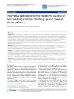
3.3 Simulation results in urban environment (with
obstacles scenario)
Figure 11a-c shows the PDRs of FAST, RBVT-R,
GyTAR, GPCR and GPSR VANET routing protocols.
The PDR was calculated with 15 flows by varying three
parameters such as the Constant Bit Rate (CBR) data
range from 0.5 to 5.0 packets per second, parallel UDP
flo ws, and the netwo rk densities were 100, 150 and 200
nodes. Figure 11a-c shows the PDR of proposed FAST
is about 12, 16, 28 and 32% higher than RBVT-R,
GyTAR, GPCR and GPSR respectively. It can also be
observed from all cases that PDR increases when packet
rate increases, which shows the protocols can transfer
more data packets in the network. As depicted in Figure
11b,c when node density is higher (i.e., 150 and 200
nodes), RBVT-R has be tter performance as co mpared to
GyTAR in some cases. This is partially due to geogra-
phical forwarding method that forwards data packets
more quickly in dense networks. The PDR of GyTAR is
about 16% less than FAST protocol. GyTAR divided the
area between intersections into small group (called
cells). GyTAR used greedy forwarding scheme to select
next node in the streets. The selection procedure to find
the best candidate node is probably the reason for the
low accuracy in GyTAR.
TheGPSRandGPCRaremoreaffectedinthepre-
sence of obstacles and PDR are consistently less than
other protocols. The performance of FAST protocol is
16-28% higher than GPCR and GPSR. This is because of
the local maxima frequently encountered and the data
packets rerouted that may cause more packets dropped.
Although, the PDR of GPCR are slightly higher in some
cases (as depicted in Figure 11a-c. There are two rea-
sons for these results. First, it is likely that there are
non-empty intersections with enough vehicles to for-
ward messages. Second, the packet did not stuck in
local maxima. Figure 12a-c shows that the FAST has
about 20, 30, 65 and 80% lower average delay than
GyTAR, RBVT-R, G PCR and GPSR routing protocols.
The av erage delays of FAST are ab out 2.5 and 2.3s
when nodes densities are 100 and 150. The delay further
decreased to less than 2.0s when node density increases
to 200 nodes. This is because in the proposed FAST the
nodes do not forward the message across the
(a) PDR using 100 nodes (b) PDR using 150 nodes
(
c
)
PDR using 200 nodes
Figure 11 Simulation results of PDR for FAST, RBVT-R, GyTAR, GPCR, and GPSR with obstacles using different CBR and node densities.
Khokhar et al. EURASIP Journal on Wireless Communications and Networking 2011, 2011:178
/>Page 11 of 15
intersection that may cause long time to reach at desti-
nation node. The average delay of FAST decreases when
node densities are increased in all cases. The main rea-
son is that the routes remain active for longer periods
of time as number of nodes increases. The source node
repairs the route and fewer packets need to be buffered.
GyTAR has 20% higher end-to-end delay t han FAST
in case of lower node density, 100 nodes, as shown in
Figure 12a. GyTAR faces the problem of local optimum
in sparse network as the next forwarding node might
not be close to the next anchor. The average delays of
RBVT-R are about 0.75s higher than FAST protocol in
all cases, as depicted in Figure 12a-c. Similarly, the aver-
age delays of GPCR and GPSR are apparently higher
than other prot ocols in first two cases, in Figure 12a,b.
However, in case of dense network the difference is
reduced about 1s, as shown in Figure 12c. This is
because of GPCR and GPSR forward data packets
between intersections based on the location of destina-
tion node. There are two side effects of this approach
such as (1) it might be possible that the road segments
are congested and overall quality of communication suf-
fers significantly, and (2) the data packets forward across
the intersection that may take high delay.
The number of hops received at destination for all
protocols are illustrated in Figure 13a-c. FAST received
about 20, 3 5, 40 and 50% less number of hops as com-
pared to GyTAR, GPCR, GPSR and RBVT-R, respec-
tively, in all cases. We can observe in all cases that the
GyTARhaveslightlyhighnumberofhopscountthan
FAST. The greedy forwarding methods used in this pro-
tocol that forward data packets on road segments need
some improvement for more accurate results. FAST has
significance difference of hops count than GPCR in all
cases, as depicted in Figure 13a-c because the presence
of cross-links between source to destination cause zero
hop count contribution. When number of nodes
increases, the hop count increases consistently for
GPSR. In GPSR, the planarization prevents packets from
making large steps to the destinations. The number of
(a) Average delay using 100 nodes (b) Average delay using 150 nodes
(c) Average delay using 200 nodes
Figure 12 Simulation results of average delay for FAST, RBVT-R, GyTAR, GPCR, and GPSR with obstacles using different CBR and node
densities.
Khokhar et al. EURASIP Journal on Wireless Communications and Networking 2011, 2011:178
/>Page 12 of 15
hops in all cases is higher for RBVT-R. The reason for
this low result is that RBVT-R gives preference to link
quality over f orward progress when selecting the next
neighbor node.
3.4 Simulation results in urban environment (without
obstacles scenario)
In this scenario, the same Suffolk city map is used in
with obstacle scenario. The obstacles are removed from
the map in order to e valuate the performance of proto-
cols under increased network congestion. The increase
in the level of data sending rate will give us the notice-
able increase in the level of contention in the network.
The transmission range is set to 250 m for 150 nodes.
With this range, it might be possible that the nodes can
communicate with other nodes on the parallel streets.
Figure 10 shows minimum distance between few streets
less than 250 m. The 150 nodes are placed on the map
using the random placement model and repeat the
experiment for 15 flows. In each experiment, ten source
and destination nodes pairs with different CBR and
UDP packets are selected randomly. The other simula-
tion parameters are almost the same as described in
Table 3.
To evaluate the performance of protocols, the PDR
and average delay are used by increasing packet/second
from 0.5 to 5. The results for other node densities that
were used in with obstacle scenario are same as for 150
nodes density. T herefore, only this scenario is used to
describe the results for without obstacle.
Figure 14a shows the experimental results of FAST,
RBVT-R,GyTAR,GPCRandGPSRusingPDR.FAST
has 5, 15, 17, 32 and 35% better performance of PDR
than RBVT-R, GyTAR, GPCR and GPSR, respectively.
The main reason for better performance of FAST is due
to fuzzy-assisted friendship mechanism under dense net-
work. As the RBVT-R use geographical forwarding
method, the PDR is slightly lower than FAST. The
(a) Number of hops using 100 nodes (b) Number of hops using 150 nodes
(
c
)
Number of hops using 200 nodes
Figure 13 Simulation results of number of hops for FAST, RBVT-R, GyTAR, GPCR, and GPSR with obstacles using different CBR and
node densities.
Khokhar et al. EURASIP Journal on Wireless Communications and Networking 2011, 2011:178
/>Page 13 of 15
PDRs of GyTAR protocol is less than 15 to 20% from
FAST. Similarly, t he PDR’s of GPCR and GPSR are les-
ser than other protocols under added congestion.
There are two reasons for less accuracy of these proto-
cols.First,greedyforwarding fails used in these proto-
cols due to many dead-end roads in Suffolk city map.
Second, there are some cases where the data packets
reach a local maxima and forwarding mode of each
packet set to perimeter forwarding that causes the
packet get trapped into routing loops. Figure 14b
shows the average delay of all routing protocols. As
the packet rate/second increases in the networks, the
average delay of all protocols increase. FAST shows
the better performance of average delay than other
protocols with maximum 1.5s. A verage delay of other
protocols increase that clearly shows high contention
in the networks.
4 Conclusion
In this article, we proposed a FAST protocol called
FAST to make better routing decisions in urban vehicu-
lar environments. Instead of simply forwarding the mes-
sages to the next available node towards destination,
FAST makes dynamic routes based on friendship
mechanism and fuzzy inference system for significance
performance of VANET routing protocol. The simula-
tion results in urban environment for with and without
obstacles scenario show that the FAST has high PDR,
lowaveragedelay,fewerhopscountsascomparedto
some existing VANET routing protocols.
Our future study includes designing a comprehensive
and fully operational misuse and anomaly intrusion
detection system f or FAST proto col. Also, we are cur-
rently working on the design of a mechanism to tune
fuzzy membership function universes with the volatile
characteristics of VANET. Our i ntended optimization
algorithms are Artificial Bees Algorithm, Genetic Algo-
rithm or Particle Swarm Optimization. Then, the one
offer less computation overhead will be the choice in
vehicular environment.
Acknowledgements
We would like to thank University of Malaya to provide fund for this
research and many thanks to anonymous reviewers for their useful criticism
and suggestions to improve the quality of this article.
Author details
1
Faculty of Computer Science and Information Technology, University of
Malaya, 50603 Lembah Pantai, Kuala Lumpur, Malaysia
2
Faculty of Computer
Science and Information Systems, Universi ti Teknologi Malaysia, 81310
Skudai, Johor, Malaysia
3
Department of Computer Science and Information
Engineering, National Quemoy University, Jinning, Kinmen 892, Taiwan, ROC
Competing interests
The authors declare that they have no competing interests.
Received: 20 July 2011 Accepted: 23 November 2011
Published: 23 November 2011
References
1. B Karp, HT Kung, GPSR: greedy perimeter stateless routing for wireless
networks, in MobiCom ‘00: Proceedings of the 6th annual international
conference on Mobile computing and networking, New York, NY, USA (ACM),
pp. 243–254 (2000)
2. C Lochert, M Mauve, H Fubler, H Hartenstein, Geographic routing in city
scenarios. SIGMOBILE Mob Comput Commun Rev. 9,69–72 (2005)
3. K Lee, M Le, J Harri, M Gerla, LOUVRE: landmark overlays for urban vehicular
routing environments. in IEEE 68th Vehicular Technology Conference, 2008.
VTC 2008-Fall 1–5 (2008)
4. M Jerbi, SM Senouci, T Rasheed, Y Ghamri-Doudane, Towards efficient
geographic routing in urban vehicular networks. IEEE Trans Veh Technol.
58(9), 5048–5059 (2009)
5. J Nzouonta, N Rajgure, G Wang, C Borcea, VANET routing on city roads
using real-time vehicular traffic information. IEEE Trans Veh Technol. 58(7),
3609–3626 (2009)
6. KC Lee, PC Cheng, M Gerla, GeoCross: a geographic routing protocol in the
presence of loops in urban scenarios. Ad Hoc Netw. 8(5), 474–488 (2010).
doi:10.1016/j.adhoc.2009.12.005
(
a
)
Packet delivery ratio using 150 nodes without obstacles
(
b
)
Average delay using 150 nodes without obstacles
Figure 14 Simulation results of PDR and average delay for FAST, RBVT-R, GyTAR, GPCR, and GPSR without obstac les and 150 nodes
density.
Khokhar et al. EURASIP Journal on Wireless Communications and Networking 2011, 2011:178
/>Page 14 of 15
7. RH Khokhar, MN Asri, MS Latiff, MA Amin, Reactive traffic-aware routing
strategy for urban vehicular environments. Int J Ad Hoc Ubiq Comput
(2011, in press)
8. P Bose, P Morin, I Stojmenovic, J Urrutia, Routing with guaranteed delivery
in ad hoc wireless networks. Wirel Netw. 7(6), 609–616 (2001). doi:10.1023/
A:1012319418150
9. F Kuhn, R Wattenhofer, Y Zhang, A Zollinger, Geometric ad-hoc routing: of
theory and practice, in PODC ‘03: Proceedings of the twenty-second annual
symposium on Principles of distributed computing, New York, NY, USA (ACM),
pp. 63–72 (2003)
10. K Lee, J Haerri, U Lee, M Gerla, Enhanced perimeter routing for geographic
forwarding protocols in urban vehicular scenarios, in Globecom Workshops,
2007, pp. 1–10 (IEEE, 2007)
11. KH Chen, CR Dow, SC Chen, YS Lee, SF Hwang, HarpiaGrid: a geography-
aware grid-based routing protocol for vehicular ad hoc networks. J Inf Sci
Eng. 26, 817–832 (2010)
12. B Leong, B Liskov, R Morris, Geographic routing without planarization, in
NSDI’06: Proceedings of the 3rd conference on Networked Systems Design &
Implementation, Berkeley, CA, USA (USENIX Association), p. 25 (2006)
13. YJ Kim, R Govindan, B Karp, S Shenker, Geographic routing made practical,
in Proceedings of the 2nd conference on Symposium on Networked Systems
Design & Implementation, vol. 2. NSDI’05, Berkeley, CA, USA (USENIX
Association), pp. 217–230 (2005)
14. SA Razak, SM Furnell, NL Clarke, PJ Brooke, Friend-assisted intrusion
detection and response mechanisms for mobile ad hoc networks. Ad Hoc
Netw. 6, 1151–1167 />(2008). doi:10.1016/j.adhoc.2007.11.004
15. SA Razak, N Samian, MA Maarof, SM Furnell, NL Clarke, PJ Brooke, A friend
mechanism for mobile ad hoc networks. J Inf Assur Secur. 4, 440–448
(2009)
16. C Huang, I Chen, K Hu, H Shen, Y Chen, D Yang, A load balancing and
congestion-avoidance routing mechanism for teal-time traffic over vehicular
networks. Univer Comput Sci. 15(13), 2506–2527 (2009)
17. K Zrar Ghafoor, K Abu Bakar, M van Eenennaam, R Khokhar, A Gonzalez, A
fuzzy logic approach to beaconing for vehicular ad hoc networks.
Telecommun Syst 1–11 (2011)
18. E Mamdani, Application of fuzzy logic to approximate reasoning using
linguistic synthesis. IEEE Trans Comput. C-26(12), 1182–1191 (1977)
19. L Briesemeister, G Hommel, Role-based multicast in highly mobile but
sparsely connected ad hoc networks, in MobiHoc ‘00: Proceedings of the 1st
ACM international symposium on Mobile ad hoc networking & computing,
Piscataway, NJ, USA (IEEE Press), pp. 45–50 (2000)
20. F Li, Y Wang, Routing in vehicular ad hoc networks: a survey. IEEE Veh.
Technol Mag. 2(2), 12–22 (2007)
21. J Bernsen, D Manivannan, Unicast routing protocols for vehicular ad hoc
networks: a critical comparison and classification. Pervas Mob Comput. 5,
1–
18 (2009). doi:10.1016/j.pmcj.2008.09.001
22. KC Lee, U Lee, M Gerla, Survey of routing protocols in vehicular ad hoc
networks. in IGI Global 2010
23. Tiger: tiger/line and tiger-related products. U.S. Census Bureau, http://www.
census.gov/geo/www/tiger/ (2011)
24. Swans++: Swans++ Simulator, />projects/swans++/ (2011)
25. DR Choffnes, FE Bustamante, An integrated mobility and traffic model for
vehicular wireless networks, in VANET ‘05: Proceedings of the 2nd ACM
international workshop on Vehicular ad hoc networks, New York, NY, USA
(ACM), pp. 69–78 (2005)
doi:10.1186/1687-1499-2011-178
Cite this article as: Khokhar et al.: Fuzzy-assisted social-based routing for
urban vehicular environments. EURASIP Journal on Wireless
Communications and Networking 2011 2011:178.
Submit your manuscript to a
journal and benefi t from:
7 Convenient online submission
7 Rigorous peer review
7 Immediate publication on acceptance
7 Open access: articles freely available online
7 High visibility within the fi eld
7 Retaining the copyright to your article
Submit your next manuscript at 7 springeropen.com
Khokhar et al. EURASIP Journal on Wireless Communications and Networking 2011, 2011:178
/>Page 15 of 15