Báo cáo hóa học: " Hybrid FIB milling strategy for the fabrication of plasmonic nanostructures on semiconductor substrates" potx
Bạn đang xem bản rút gọn của tài liệu. Xem và tải ngay bản đầy đủ của tài liệu tại đây (1.15 MB, 5 trang )
NANO EXPRESS Open Access
Hybrid FIB milling strategy for the fabrication of
plasmonic nanostructures on semiconductor
substrates
Joshua F Einsle
1*
, Jean-Sebastien Bouillard
2
, Wayne Dickson
2
and Anatoly V Zayats
2
Abstract
The optical properties of plasmonic semiconductor devices fabricated by focused ion beam (FIB) milling deteriorate
because of the amorphisation of the semiconductor substrate. This study explores the effects of combining
traditional 30 kV FIB milling with 5 kV FIB patterning to minimise the semiconductor damage and at the same time
maintain high spatial resolution. The use of reduced acceleration voltages is shown to reduce the damage from
higher energy ions on the example of fabrication of plasmonic crystals on semiconductor substrates leading to 7-
fold increase in transmission. This effect is important for focused-ion beam fabrication of plasmonic structures
integrated with photodetectors, light-emitting diodes and semiconductor lasers.
Introduction
Plasmonic nanostructures are finding ever increasing
number of applications in various a reas of photonics
and optoelectronics [1-3]. While initial investigations
into the o ptical properties of plasmonic systems have
been almost exclusively done with metallic nanostruc-
tures on ‘passive’ dielectric substrates, such as silica or
quartz, the real-world applications in many cases require
the use of semiconductor substrates. Recently, there has
been a demand on incorporating plasmonic nanostruc-
tures in active photonic devices, such as light-emitting
diodes (LEDs), semiconductor lasers and photodetectors,
to improve their performance [4-7].
For applications in visible and near-infrared spectral
ranges, the plasmonic structures need to be fabricated
with a precision on the order of tens of nanometers.
Conventional microelectronics fabrication methods,
such as v isible and UV litho graphy and broad-beam ion
etch, do not allow controlling feature sizes on such
length scales. The two main methods for the fabrication
of plasmonic nanostructures relies on using charged
particle beams to structure the material. For example,
electron beam lithography can be combined with either
lift-off or an etch step to produce nanoscale structures.
Electron beam lithography though is not the most effi-
cient process and requires further processing befor e the
final device is created. While robust, this process does
not offer sufficient flexibility for quick and rapid proto-
typing. On the other hand, focused ion beam (FIB)
milling is widely accepted as a method of choice for
rapid prototyping of electronic and photonic compo-
nents requiring critical parameters at the subwavelength
scale. FIB can sputter away bulk material with nanoscale
spatial localisation. The FIB approach offers a simple
method to structuring bulk materials, by providing a
maskless process that circumvents the pitfalls of resist-
based lithography processes. A large variety of photonic
and plasmonic devices with struc turally controlled opti-
cal properties can be created using FIB milli ng
[1-3,8-10]. While excellent for fabrication of plasmonic
structures on dielectric substrates, FIB patterning results
in the deterioration of optical properties of semiconduc-
tors because of ion-beam-induced amorphisation and
Ga
+
implantation [11-13]. From FIB applications for
milling semiconductor materials for transmission elec-
tron microscope (TEM) investigations, it is known that
the 30 kv FIB damages approximately 50 nm of the GaP
crystal through amorphisation (see, e.g., [10,12] and
Peterson and Blackwood (2010, personal
communication)).
The influence of FIB milling on the optical properties
of the semiconductor surface can be seen from the
* Correspondence:
1
Centre for Nanostructured Media, IRCEP, The Queen’s University of Belfast,
Belfast, BT7 1NN, UK
Full list of author information is available at the end of the article
Einsle et al. Nanoscale Research Letters 2011, 6:572
/>© 2011 Einsle et al; licensee Springer. This is an Open Access a rticle distributed under the terms of the Creative Commons Attribution
License (http://creativecom mons.org/licenses/by/2.0), which permits unrestricted use, distribution, and reproduction in any medium,
provided the orig inal work is properl y cited .
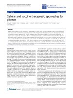
performance of two LEDs whose emission face has been
etched under different FIB patterning parameters (Figure
1). One LED was patterned usin g a 30 pA at 30 kV
beam setting, while the other LED was etched u sing 50
pA at 30 kV. The total mill time varied from 0 to 60s.
A remarkable degradation in the light emitting from th e
devices has been observed. Since FIB-milled plasmonic
crystals are routinely used now for investigations
towards the improvement of LED and photodetector
performance, the above-described effect may be very sig-
nificant in determining a f inal performance of devices.
In this letter, we demonstrate a strategy for minimising
FIB-induced effects on plasmonic crysta l transmission
on semiconductor surfaces. It is known that the sub-
strate damage can be reduced with the use of low
energy ions but this also r esults in a loss of resolution.
Here, we employ a hybrid approach to plasmonic struc-
ture fabrication to mitigate substrate damage and at the
same time maintain high spatial resolution.
Methods
GaP substrates were used in these experiments as a
representative for the InGaAs family of semiconductors.
The fabricated plasmonic nanostructures are plasmonic
crystals consisting of arrays of periodically arranged
cylindrical apertures in a 100-nm Au film deposited on
GaP substrates. The Au films were magnetron sputtered
on the GaP substrates. Then, an FEI Nova 600 Dual
Beam equipped with a Sidewinder FIB column was used
to etch away selected regions of the Au film. To pre-
cisely control FIB mills, stream patterning files were
used. Using FEI’s PS Convert, pattern files are generated
by inputting FIB-milling parameters such as horizontal
field width, spot size, beam over lap (space between
points in the pattern) and dwell time. The software then
generates a file specifying pixel location and dwell for
each point in the pattern. The choice of the input para-
meters allows controlling the overall depth of the aper-
ture arrays created. Stream files provide fast and easy
Figure 1 Optical Performance of FIB patterned LED. (a) LED emission intensity as a function of th e FIB exposure dose. (b) Optical image of
the LED patterned with box mills of different 30 kV FIB doses. LEDs used for milling have been provided by OSRAM Opto-Semiconductors.
Einsle et al. Nanoscale Research Letters 2011, 6:572
/>Page 2 of 5
control over the various patterns required to mill arrays
with various accelerating voltage conditions.
The standard approach for the fabrication of surface
plasmon polaritonic crystals (SPPC) relies on removing
selected regions of A u using ions accelerated t hrough a
30-kV potential. This results in an FIB capable of pro-
viding high-resolution patterning capabilities but the
high energy ions introduce d amage to a semiconductor
substrate. A hybrid milling strate gy combining high and
low energy ion beams has been developed previously for
TEM lamella fabrication. It was used however to remove
bulk regions of material and not to create fine struc-
tures. In this study, we have adopted fabrication which
includes initial milling employing focused ions acceler-
ated at 30 kV with a 5-kV ion beam performing the
final thinning and polishing to achieve the required
thicknessandatthesametimeremovethe30kV
beam-induced damage layer [13]. The use of higher
energy ions for nanostructuring allows the process to
maintain a high throughput along with high spatial reso-
lution. At the same time, 5 kV ions do not create a deep
layer of amorphous material but have disadvantage of
low mill rates and decreased resolution. The structures
presented below have been created by milli ng up to 70%
of bulk Au film with the standard (30 keV) ion beam
energy, and then removing the remaining Au film with
the 5 keV ion beam (Figure 2a). While the latter pro-
vides lower resolution, the feature size is determi ned by
the high energy ions pre-patterned structure.
For milling optimisation, several plasmonic crystals
consisting of square arrays (600 nm period) of cylindri-
cal apertures (200 nm diameter) have been fabricated
under diffe rent milling conditions (Table 1). Structure A
represents the conventional milling ap proach exclusively
using a 30-kV ion beam and not imaging the substrate
with the FIB before or after milling the array.
Structure B was fabricated to investigate the effect of
imaging a 30-kV fabricated array with the 5-kV beam.
Owing to the reduced signal in the low kV image, per-
fect overlay of the 5- and -30 kV patterns required in
the hybrid FIB approach is challenging to achieve. As a
result, the overlay alignment could not be achieved
without taking a sequence of high resolution images
with the 5 kV ion beam. These were used to bring the
30 kV structure into the field of view such that the 5 kV
mill pattern could be accurate ly overlaid with the 30 kV
milled features. The alignment images have the net
effect of removing material from the entire region
imaged. The amount of gold sputtered was measured
via cross-sectional images to be around 10 nm. It would
be ideal to be able to eliminate the two images, however
the d amage induced by taking these two images seems
to be minimal as demonstrated in the results shown
below.
Structures C and D represent removing 50 nm of Au
using t he 30 kV beam. The remaining 50 nm of Au in
theapertureholesareremovedviaacombinationof
imaging and patterning. Finally, for structure E, 70 nm
Figure 2 SPPC hybrid milling routine. (a) Schematic of the hybrid milling routine employed. (b,d) SEM images and (c,e) SEM cross sections of
SPPC crystals in structure A (b,c) and structure E (d,e).
Table 1 Hybrid milling conditions used for SPPC
fabrication
Structure 30-kV mill time (s) 5-kV mill time (s)
A 5 N/A
B 5 Image only
C3 22
D3 45
E4 45
Einsle et al. Nanoscale Research Letters 2011, 6:572
/>Page 3 of 5
of Au was removed via 30 kV patterning leaving the
remainder to be removed with the 5 kV beam. The fab-
ricated structures show good quality of fabricated SPPCs
(Figure 2b,c). The cross sections of the structures fabri-
cated by different milling approaches are very similar.
Results and discussion
Optical characterisation of the structures was performed
by measuring optical transmission spectra of the plas-
monic crystals as de scribed by Bouillard et al. [14]. Both
zero-order transmission and transmission dispersion
were measured (Figure 3). The observed spectra are
typical for plasmonic crystals on high-refractive index
substrates [9]. No transmission is observed below about
520 n m where the GaP substrate becomes strongly
absorbing. The plasmonic crystal transmission is simpler
on high-refractive index substrates than on glass because
of the fact t hat GaP/Au interface does not support sur-
face plasmon polaritons (SPPs) in the spectral range
below about 620 nm because of the ε
GaP
+ ε
Au
>0,so
that only SPP modes on the Au/air interface are impor-
tant. Two main peaks obs erved in all structures are
associated with (±1, 0) Bloch modes of the Au-Air inter-
face (Figure 3b) that can be derived from the conven-
tional SPP Bragg scattering conditions [3].
All five structures A-E exhibit similar transmission
spectra with the same position of the plasmo nic reso-
nances, it can be concluded that all single high-energy
and double high/low-energy mills have produced aper-
ture arrays with similar parameters and not signifi-
cantly altered the geometry of the apertures, since the
transmission spectra are very sensitive to the shape of
the apertures. The most prominent difference in the
transmission of the structures is the significantly
increased transmission for the structures milled with
the low kV approach. The main transmission peak
around 660 nm shows a greater than sevenfold
increase for the structures made with the hybrid
milling when compared to the 30 kV patterning. The
standard 30-kV milled structure shows lowest trans-
mission. As seen in device B, simply imaging the struc-
ture with low kV ions improves the transmission
because of the partial removal of the semiconductor
damaged layer. The three structures milled with hybrid
approach exhibit highest transmission.
Conclusion
We have described a hybrid milling approach for fabri-
cating plasmonic crystals on semiconductor substrates.
Combining two different accelerating voltages to etch
the plasmonic crystal, we can achieve minimal overall
damage to the semiconductor substrate keeping high-
resolution capabilities of the ion-beam-based techniques.
Reducing the amorphisation of the substrate results in
over sevenfold increase of the optical transmission of
semiconductor/metal nanostructures because of the
reduction of the sem iconductor surface damage. This
FIB-milling process extends the ability of the technology
to fabricate plasmonic and other nanostructures on sub-
strates which are usually damaged through traditional
FIB patterning approach by maintaining high spatial
resolution of high-energy milling and lower damage
introducing by low-energy ion beams.
Abbreviations
FIB: focused ion beam; LED: light emitting diode; SEM: scanning electron
microscope; SPP: surface plasmon polarition; SPPC: surface plasmon
polaritonic crystal; TEM: transmission electron microscope.
Acknowledgements
This study was supported in part by the EC FP7 project PLAISIR, EC FP6
project PLEAS and EPSRC (UK). The authors thank Juergen Moosburger
(OSRAM Opto-Semiconductors) for providing LED samples and Brendan
Peterson, J.J. Blackwood, Ross Stanley and Andrea Dunbar for the discussion
Figure 3 Hybrid milling optical characterisation. (a) Zero-order transmission spectra of the SPPCs in structures A-E. (b) Transmission
dispersion measured for SPPCs fabricated using optimum hybrid FIB milling strategy (Structure E). Lines represent the estimation of SPPC band
gap using the Bragg conditions.
Einsle et al. Nanoscale Research Letters 2011, 6:572
/>Page 4 of 5
of GaP amorphisation during FIB processing. JE would like to thank FEI for
tuition assistance.
Author details
1
Centre for Nanostructured Media, IRCEP, The Queen’s Univ ersity of Belfast,
Belfast, BT7 1NN, UK
2
Department of Physics, King’s College London, Strand,
London WC2R 2LS, UK
Authors’ contributions
JFE developed the hybrid milling routine. JFE, JSB and WD carried out
optical characterisation measurements. All authors analysed the data. All
work was supervised by AVZ. All authors read and approved the final
manuscript.
Competing interests
The authors declare that they have no competing interests.
Received: 16 August 2011 Accepted: 31 October 2011
Published: 31 October 2011
References
1. Ebbesen TW, Genet C, Bozhevolnyi SI: Surface-plasmon circuitry. Phys
Today 2008, 61(5):44-50.
2. Barnes WL, Dereux A, Ebbesen TW: Surface plasmon subwavelength
optics. Nature 2003, 424(6950):824-830.
3. Zayats AV, Smolyaninov I, Maradudin AA: Nano-optics of surface plasmon
polaritons. Phys Rep Rev Sect Phys Lett 2005, 408(3-4):131-314.
4. Windisch R, Linder N, Wiesmann C, Streubel K: Nanostructured LED’s for
solid- state lighting. IEEE/LEOS Winter Topicals Meeting Series 2009,
2009:10-11.
5. Zia R, Schuller JA, Chandran A, Brongersma ML: Plasmonics: the next chip-
scale technology. Mater Today 2006, 9(7-8):20-27.
6. Atwater HA, Polman A: Plasmonics for improved photovoltaic devices.
Nat Mater 2010, 9:205-213.
7. McCarron R, O’Connor D, Dickson JSBW, Zayats AV: Light extraction
beyond total internal reflection using one-dimensional plasmonic
crystals. Appl Phys Lett 2011, 99:081106.
8. Tjerkstra R, Segerink F, Kelly J, Vos W: Fabrication of three-dimensional
nanostructures by focused ion beam milling. J Vac Sci Technol B:
Microelectron Nanometer Struct 2008, 26(3):973-977.
9. Drezet A, Przybilla F, Laux E, Mahboub O, Genet C, Ebbesen TW,
Bouillard JS, Zayats A, Spevak IS, Zayats AV, Nikitin AY, Martin-Moreno L:
Opening the light extraction cone of high index substrates with
plasmonic gratings: light emitting diode applications. Appl Phys Lett 2009,
95(2):021101.
10. Schrauwen J: Focused ion beam processing of nanophotonic structures.
PhD thesis University of Ghent; 2009.
11. Jinschek JR, Radmilovic VR, Kisielowski C: FIB preparation for HRTEM: GaN
based devices. Microscop Microanal 2004, 10(S02):1142-1143.
12. Giannuzzi L, Geurts R, Ringnalda J: 2 keV Ga+ FIB milling for reducing
amorphous damage in silicon. Microscop Microanal 2005, 11(S02):828-829.
13. Mayer J, Giannuzzi LA, Kamino T, Michael J: TEM sample preparation and
FIB- induced damage. MRS Bull 2007, 32:400-407.
14. Bouillard JS, Einsle J, Dickson W, Rodrigo SG, Carretero-Palacios S, Martin-
Moreno L, Garcia-Vidal FJ, Zayats AV: Optical transmission of periodic
annular apertures in metal film on high-refractive index substrate: the
role of the nanopillar shape. Appl Phys Lett 2010, 96(20):201101.
doi:10.1186/1556-276X-6-572
Cite this article as: Einsle et al.: Hybrid FIB milling strategy for the
fabrication of plasmonic nanostructures on semiconductor substrates.
Nanoscale Research Letters 2011 6 :572.
Submit your manuscript to a
journal and benefi t from:
7 Convenient online submission
7 Rigorous peer review
7 Immediate publication on acceptance
7 Open access: articles freely available online
7 High visibility within the fi eld
7 Retaining the copyright to your article
Submit your next manuscript at 7 springeropen.com
Einsle et al. Nanoscale Research Letters 2011, 6:572
/>Page 5 of 5