Báo cáo hóa học: " A QoS guaranteeing MAC layer protocol for the “underdog” traffic" ppt
Bạn đang xem bản rút gọn của tài liệu. Xem và tải ngay bản đầy đủ của tài liệu tại đây (848.66 KB, 15 trang )
RESEARCH Open Access
A QoS guaranteeing MAC layer protocol for the
“underdog” traffic
Mahasweta Sarkar
1*
and Christopher Paolini
2
Abstract
With the tremendous boom in the wireless local area network arena, there has been a phenomenal spike in the
web traffic which has been triggered by the growing popularity of real-time multimedia applications. Towards this
end, the IEEE 802.11e medium access control (MAC) standard specifies a set of quality-of-service (QoS)
enhancement features to ensure QoS for these delay sensitive multimedia applications. Most of these features are
unfair and inefficient from the perspective of low priority (non-real time) traffic flows as they tend to starve the
non-real time flows depriving them of appropriate channel access, hence throughput. To that extent, this article
proposes a MAC protocol that ensures fairness in the overall network performance by still providing QoS for real-
time traffic without starving the “underdog” or non-real-time flows. The article first presents analytical expressions
supported by Matlab simulation results which highlight the performance drawbacks of biased protocols such as
802.11e. It then evaluates the efficiency of the proposed “fair MAC protocol” through extensive simulations
conducted on the QualNet simulation platform. The simulation results validate the fairness aspect of the proposed
scheme.
1. Introduction
Financial organizations, business houses and healthcare
facilities have recently and repeatedly complained
against network resource hogging by multimedia traffic
when a minority section of their staff chooses to strea m
a video clip on Youtube which sabotages the transmis-
sion of an important data file like a patient’s health
record or a crucial ema il exchange [1,2]. This article
investigates into alleviating this situation. With the
widespread deployment of wireless local area networks
(WLAN) in diverse environments, the demand for sup-
porting a diverse range of applications is becoming
increasingly important. Performance sensitive traffic
such as voice and video applications require stringent
delayconstraintswhiledatapacketsofafiletransfer
application, for example, can operate over a much
broader delay and throughput requirement. To provide
differentiated service to several such different categories
of traffic, the IEEE 802.11e medium access control
(MAC) standard [3] has the provision of traffic classifi-
cation and prioritization. The standard classifies network
traffic into four different priority level or access cate-
gories (ACs). Each QoS-enabled station has four ACs,
two high priority (HP) queues and two low priority (LP)
queues. The packets delivered from the higher layers are
tagged with priority values and en-queued into the cor-
responding priority queue according to the mapping
illustrated in Table 1.
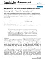
Each AC has its own transmit queue and i ts own set
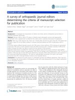
of AC parameters. Figure 1 shows a model where nodes
maintain separate queues for each AC and packets at
the head-of-line (HOL) of each queue contend for chan-
nel access using AC-specific parameters [4] which are
more favorable to HP traffic than the LP traffic. The
hybrid coordinator function (HCF)-controlled channel
access (HCCA) mechanism is define d for parameterize d
QoS support. It uses a QoS-aware centrali zed coordina-
tor, called the hybrid coordinator (HC) allocated with
the QoS-enabled access point of the QoS-enabled basic
service set (BST) and has highest priority to access the
wireless medium to issue polls to stations to provide
limited-duration-contr olled access phase for contention-
free transmission of QoS data. The HCF operates during
the CP and CFP durations for providing QoS support
for strict real-time applications.
* Correspondence:
1
Electrical and Computer Engineering, San Diego State University, 5500
Campanile Drive, San Diego, CA 92182, USA
Full list of author information is available at the end of the article
Sarkar and Paolini EURASIP Journal on Wireless Communications and Networking 2011, 2011:131
/>© 2011 Sarkar and Paolini; licensee Springer. This is an Open Access article distributed under the terms of the Creative Commons
Attribution License ( which permits unrestricted use, distribution, and reproduction in
any medium, provided the original work is properly cite d.
Such a mechanism facilitates differentiated QoS where
HP, performance intensive traffic such as voice and
video applications will enjoy less delay and greater
throughput, compared to LP traffic (e.g., file transfer)
[5,6]. The QoS features in IEEE 802.11e raise two
related concerns. First, these mechanisms can often be
unfair and inefficient from the perspective of nodes car-
rying LP traffic. Second, selfish nodes can gain enhanced
performance by classifying LP tr affic as HP, potentially
destroying the QoS capability of the system.
We envision a system where majority of traffic is non-
real time, for example, in organizations like the health-
care industry, stock markets, and edu cational institu-
tions, the bulk of the traffic still comprises of non-real-
time flows. In these scenarios, it becomes essential to
provide acceptable performance metrics for these non-
real-timetrafficinthefaceof growing real-time multi-
media traffic. The 802.11e MAC sch eme could have
been justified if the majority of traffic in the system was
real time. However, in these scenarios where the major
chunk of network traffic is non-real time, the protocol
will starve the non-real-time traffic which is the domi-
nant traffic in most of these organizations and can
present critical performance issues and diminish user
satisfaction if not handled smartly [1,2]. Even a lone
rea l-time flow can hog the network and starve the non-
real-time flows thereby drastically affecting the network
performance [7]. This article raises the following con-
cerns: (i) will the s tandard still favor HP traffic at the
cost of LP traffic starvation, especially when the network
traffic is LP-centric? (ii) what will happen if the applica-
tions start falsely classifying their traffic as HP in pursuit
of preferen tial service [8]? Such instances might destroy
the QoS capabilities of the network. The research com-
munity has raised concern over these issues of fairness
[8-11]. The standard does not address these issues as it
mainly deals with HP traffic, for which it allocates a
major share of its resources.
This motivates us to propose a MAC protocol that
does not starve the LP traffic or “underdog” traffic in
face of HP traffic. Our scheme especially prevents
resource hogging by the few HP traffic flows even
when the predominant traffic in the network is LP. In
this article, we thereby propose a MAC scheme which
imparts fairness to the traff ic ("Underdog”), i.e., getting
exploited at the cost of preferential service offered by
the standard to real-time traffic. The purpose of
designing this scheme is to prevent starvation of non-
real-time LP data traffic while still maintaining an
acceptable quality-of-service (QoS) performance for
real time, delay sensitive HP traffic. We do so by intro-
ducing a t ransmission opportunity for LP traffic in the
contention-free phase (CFP) of an IEEE 802.11e MAC
protocol. Traditionally, IEEE 802.11e MAC would pro-
vision for only HP traffic transmission during the CFP.
In our proposed MAC scheme, we advocate the intro-
duction of transmission slots for LP traffic as well dur-
ing CFP.
Table 1 User priority to access category mapping
User priorities ACs Designation
1 AC_BK Background
2 AC_BK Background
0 AC_BE Best effort
3 AC_VI Video
4 AC_VI Video
5 AC_VI Video
6 AC_VO Video
7 AC_VO Video
Figure 1 Access categories in 802.11e EDCA model.
Sarkar and Paolini EURASIP Journal on Wireless Communications and Networking 2011, 2011:131
/>Page 2 of 15
To explicitly understand the drawbacks of IEEE
802.11e (the standard which caters primarily to HP traf-
fic) and thus motivate the need for a fair MAC protocol,
we first analyze a hybrid-MAC scheme which mimics
the 802.11e MAC in every essential respect. The analyti-
cal expressions attained for throughput and delay values
of this hybrid MAC are discussed with the help of
MATLAB simulation results. The drawbacks of an
802.11e-like MAC become apparent from these results.
We thereby propose our fair MAC scheme. We perform
extensive simulations on the network simulation plat-
form QualNet to verify the feasibility and performance
efficiency of our MAC scheme in comparison with the
basic 802.11e protocol. Simulation results validate the
performance efficiency of our scheme.
The rest of the article is o rganized as follows. In Sec-
tion 2, we provide a system model for our 802.11e-like
Hybrid-MAC and derive throughput and delay expres-
sions for the MAC along with MATLAB simulation
results. In Section 3, we present and discuss our pro-
posed MAC scheme. In Section 4, we present QualNet
simulation results and provide an analysis and a com-
parative study of our scheme with 802.11e. We finally
conclude the article in Section 5.
2. Analysis of a hybrid-MAC
We intend to derive analytical expressions for modeling
throughput and delay characteristics of a MAC protocol
that mimi cs the IEEE 802.11e in every essential respe ct.
We do so by first proposing a simplified model of the
IEEE 802.11e MAC.
2.1 System model
We set o ut to analyze the 802.11e MAC protocol. We
realize that an analysis of the exact scheme is cumber-
some.Wethusproposeahybrid-MACmodelthat
resembles the 802.11e MAC in most essential respects.
Our MAC model provides us with an abstraction of the
essential features of 802.11e MAC, while avoiding the
complex details of the latter. We believe that the
insights obtained using our model are applicable to the
802.11e scenario. Our system model can be thought of
as a hybrid MAC model which operates in both the
contention and CFPs alternately, akin to a legacy 802.11
MAC protocol [4] with both its (a) distributed coordina-
tion function (DCF) an d (b) point coordination function
(PCF) modes enabled [4]. While DCF is based on the
contention-based CSMA/CA mode of channel access,
PCF is based on the polling mechanism. Limited QoS
support in the legacy 802.11 standard is available
through the use of the PCF. The DCF phase mimics the
enhanced distributed channel access (EDCA) mechan-
ism which is a contention-based channel access scheme
while the PCF mimics the HCCA which is based on a
polling mechanism. EDCA and HCCA are used to pro-
vide prioritized and parameterized QoS services, respec-
tively, in 802.11e.
The network topology being modeled consists of a BSS
of N LP and M HP traffic flows. We assume that each
flow is generated by a node whic h we refer to as a STA
(station), as done in the 802.11 standard. During the con-
tention period (CP), each STA uses the basic access
mechanism only, that is, no STA is assumed to be hidden
from another STA and the RTS/CTS mechanism is not
employed. During the contention-free period (CFP), the
M HP traffic STAs are placed in a circular queue and are
polled sequentially by the PCF. The PCF implements two
periods of channel access in a duration of time referred
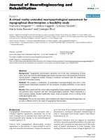
to as the “superframe": (i) a CFP and (ii) a CP. Figure 2
depicts an 802.11e superframe. The proportion of time
allocated to each period within a superframe is not
defined by the standard. The point coordinator subsys-
tem residing in an AP continues to poll STAs in its poll-
ing list until the CFP duration expires.
2.2 Modeling throughput
Our analytical model for overall system throughput is a
dimensionless multivariable function S of N, M, p,and
a,
S = S(N, M, p, α)
(1)
where p is the probability of a successful frame trans-
mission and a is a value between 0 and 1 that identifies
theratioofthetimespentintheCFPtothetotaltime
spanned by a superframe which forms a repeating inter-
val of contention and CFPs,
α =
CFP
CFP + CP
(2)
As a tends toward 0, the BSS reverts to a contention-
only-based environment where the point coordinator is
notusedtopollSTAs.Withanon-zeroa,dimension-
less throughput S becomes a weighted sum of time
spent in the CP and the CFP,
S(N , M, p, α)=(1− α)S
CP
+ αS
CFP
(3)
We then apply the definitions of S
CP
and S
CFP
given in
[12] for dimensionless throughput for each respective
period,
S
CP
=
¯
U
CP
¯
I
CP
+
¯
B
CP
(4)
S
CFP
=
¯
U
CFP
¯
B
CFP
(5)
Sarkar and Paolini EURASIP Journal on Wireless Communications and Networking 2011, 2011:131
/>Page 3 of 15
In Equation 4,
U
CP
is the average duration of time the
useful data are received by a STA during the CP,
I
CP
is
the average duration of time the channel remains idle
during the CP, and
B
CP
is the average duration of time
the channel is busy trans mitting data, the overhead bits
incurred by the data, and is handling collisions [12].
Equation 4 is then a dimensionless quantity between 0
and 1 that represents throughput efficiency as the ratio
of time the channel is used for sending useful data to
total time. We can extend this concept by defining S
CFP
in a similar way, with the exception that we exclude the
idle term in the denominator since it is assumed that
the channel is never idle during the CFP. The defini-
tions of
U
CP
,
I
CP
, and
B
CP
are extended from [12], with
the modification that the total STA count has been
replaced by (N + M),
¯
U
CP
=
(
N + M
)
Tp
1 − p
1 −
1 − p
N+M
(6)
¯
I
CP
=
σ
1 −
1 − p
N+M
(7)
¯
B
CP
=
T
s
1 − p
N+M
(8)
In Equation 6, T is the time spent in the CP trans mit-
ting useful data, that is, the ratio of the length in bits of
packet payload P (excluding the number of header and
trailer bits, H) to the data rate R.Theothertimepara-
meter, T
s
, in (8) is the time spent sensing the channel
during a successful frame transmission. Substituting (6),
(7), and (8) into (4), we obtain, as in [12],
S
CP
=
(
N + M
)
Tp
1 − p
N+M−1
T
s
+
(
σ + T
s
)
1 − p
N+M
(9)
The expression for T
s
is given by
T
s
=DIFS+
H + P
R
+SIFS+
ACK
R
+2τ
(10)
To derive E quation 10, we note that synchro nized data
exchange within the CFP are accomplished by polling
STAs. The polling process is coordinated by the PCF
implementation within an AP. When the CFP begins, the
AP wai ts a brief duration of time known as a short inter-
frame space (SIFS) which serves as a delay between bea-
con, data, acknowledgement, and end frames that are
transmitted during the CFP. The value of SIFS varies by
the particular 802.11 standard implemented by a transcei-
ver. For 802.11a, b, and g, the values are 16, 10, and 10 μs,
respectively. After waiting an initial SIFS, the AP com-
mences with polling by transmitting a Data/CF-Poll frame
to the first STA in a polling list. Data/CF-Poll frames serve
a dual purpose by piggybacking data carried by the AP
which, in an infrastructure mode network, is attached to a
wired network via a wired Ethernet interface. The Data/
CF-Poll frame polls the receiving STA while simulta-
neously carrying higher layer datagrams originating from
another STA within a BSS or a device external to a BSS
via a wired LAN. The collision avoidance (CA) mechanism
of CSMA/CA cannot guarantee collisions will not occur.
A collision can occur, for example, if two STAs compute
exactly the same backoff t ime after detecting a channel
idle for DCF interframe space duration (DIFS) and then
transmit a MPDU when the backof f timer matures. To
Figure 2 802.11e super frame showing HP traffic constrained to the CFP w hile LP and HP traffic compete for channel access during
the CP. The HC in the CP also polls stations for HP traffic.
Sarkar and Paolini EURASIP Journal on Wireless Communications and Networking 2011, 2011:131
/>Page 4 of 15
determine if a transmission resulted in a collision, each
data frame (MPDU) must be acknowledged through the
transmission of an ACK frame sent by the STA receiving a
data frame. If a sending STA does not receive a corre-
sponding ACK after waiting a SIFS period, the sending
STA concludes a coll ision occ urred an d will repeat the
transmission. DIFS values for 802.11a, b, and g are 34, 50,
andeither28or50μs, depending on s lot time, respec-
tively. In IEEE 802.11g, t he slot time can be eit her 9 μsif
no legacy 802.11b STAs are present in the BSS, or 20 μsif
the BSS has a mix of 802.11b and 802.11g STAs. DIFS is a
function of SIFS and is computed according to
DIFS = SIFS + 2σ
(11)
where s is the slot time defined to be twice the maxi-
mum propagation time τ. The slot time is therefore an
amount of time a STA requires to determine if another
STA has accessed the channel at the start of th e previous
slot. Slot time values for 802.11a and b are 9 and 20 μs,
respectively, for a PHY that uses a direct sequence spread
spectrum (DSSS) modulation technique and 50 μsfora
PHY that uses a frequency hopping spread spectrum
(FHSS) transmission method. Acknowledgement frames
may also piggyback data originating from a receiving
STA and intended for another STA in the BSS or an
external device. If the point co ordinator fails to receive a
response fro m a pol led STA within a PCF interframe
space (PIFS) period of time, the PCF will move on and
poll the next STA in its polling list. PIFS is also function
of SIFS and is computed according to
PIFS = SIFS + σ
(12)
and thus the values for 802.11a, b, and g are 25, 30,
andeither19or30μs, respectively. The PIFS duration
also serves as a gap between the CP and CFP. From (11)
and (12) we have the following inequality
SIFS < PIFS < DIFS
(13)
which prevents the PCF fro m transmitting a poll
frame in between a Data/CF-Poll and Data/CF-ACK
transaction.
Given the definitions of SIFS and DIFS, Equation 10
can be understood as the sum of time s required to con-
duct a successful packet transmission in the CP: the
STA must first wait a DIFS amount of time to detecting
a channel idle before proceeding to transmit, then an ( H
+ P)/R amount of time to for an interface to transmit a
packet consisting of H header and trailer bits and P pay-
load bits at a data rate R,thenaτ amount of time for
propagation of the data packet, then a SIFS amount of
time before the receiving STA’s interface can transmit
an acknowledgement frame, then (ACK/R)timeto
transmit the acknowledgement frame, and finally
another τ amount of time for propagation of the
acknowledgement.
Our derivation of S
CFP
proceeds in a s imilar way to
that of S
CP
.Letq represent the probability a STA has a
non-null data frame to transmit during the CFP.
U
CFP
is
the average time spent during the CFP to transmit use-
ful data. By useful data we mean data bits and not bits
belonging to beacon, pure ACK, and CF-End frames. If
we denote P
CFP
as the number of data bits transmitted
during the CFP, then
¯
U
CFP
=
P
CFP
R
(14)
where R is the fixed transceiver data rate.
To derive an expression for the mean tim e the channel
is busy in the CFP during a successful polling transaction,
denoted
B
CFP
, we need to account for all the individual
frame transmissions namely, CF
Beacon
,CF
Poll
,CF
ACK
, and
CF
Null
which represent the lengths of the beacon, Data/
CF-Poll, Data/CF-ACK , and CF-NULL frames, respec-
tively. CF-Null frames are transmitted by a polled STA if
the STA does not have any pending data to send, τ is the
propagation delay of the wireless LAN, and H is the
length of the header and frame check sequence (FCS) of
an 802.11 frame. The first term in Equation 15 is the
time required for the hybrid coo rdinator (HC) operating
in an access point to transmit a beacon frame and for the
beacon to propagate. The second term in (15) is the time
required to poll all the LP and HP stations being coordi-
nated by the HC during the CFP. The third term is the
probability all the stations have a non-null data frame
waiting to transmit upon being polled. The summation in
parenthesis is the time r equired for the corresponding
station to acknowledge the poll by returning a combined
Data/CF-ACK frame. The fourth term then accounts for
the time required for all the stations that do not have
data to send an d will transmit a CF-NULL frame back to
the HC upon being polled.
¯
B
CFP
=
PIFS +
CF
Beacon
R
+ τ
+
(
N + M
)
SIFS +
H + P +CF
Poll
R
+ τ
+
(
N + M
)
q
(N+M)
SIFS +
H + P +CF
Data/ACK
R
+ τ
+
(
N + M
)
1 − q
(N+M)
SIFS +
H + P +CF
Null
R
+ τ
+
SIFS +
CF
End
R
+ τ
(15)
2.3 Modeling delay
Our analytical model for overall system delay is a dimen-
sionless multivariable function D of N, M, p, and a,
Sarkar and Paolini EURASIP Journal on Wireless Communications and Networking 2011, 2011:131
/>Page 5 of 15
D = D(N, M, p, α)
(16)
Observe that
0 <
D
ideal
D
actual
≤ 1
(17)
where D
ideal
is the theoretical minimum delay a STA
can experience in a superframe while D
actual
is the true
delay experienced. If we define D such that
D =
1 −
D
ideal
D
actual
(18)
Then D ® 0 as the actual delay approaches the ideal
and D ® 1 as actual delay diverges from the ideal. We
first consider delay incurred by the DCF. Ideal delay in
the CP can be expressed as the sum of ideal HOL delay
and ideal queuing delay,
D
ideal
= D
HOL
ideal
+ D
Queuing
ideal
(19)
where
D
HOL
ideal
represents the minimum time required in
the CP to transmit an 802.11 frame successfully, upon
the first attempt, and i s equal to T
s
. Ideal queuing delay
is given by the Pollaczek-Khinchine formula [12]
D
Queuing
ideal
=
ρ
2μ
(
1 − ρ
)
1+cv
2
(20)
that describes the mean time a frame waits in queue
to be serviced by the MAC, where the queue is modeled
asaM/G/1queue(asingleserverwithframearrivals
having a Poisson distribution and service time having a
general distribution). Total actual delay D
actual
is mod-
eled as the sum of (20) and an expression for the
expected value of HOL delay which takes into account
backoff delay.
In Equation 21, b is the average physical time
between two decrements of the backoff counter,
CW
min
is the minimum contention window size,
P
s
=
1 − p
M+N−1
is the probability a STA’ sframe
transmission is successful, and r
max
is the maximum
number of retransmissions permitted. In our simula-
tion, CW
min
is set to 2
4
and CW
max
is set to 2
10
which
are the values used by a PHY that employs a FHSS
method of transmitting radio signals. Considering now
the PCF, each STA has an opportunity to transmit
when polled while the CFP is in progress. If the maxi-
mum predetermined duration of the CFP in a given
superframe expires before every STA has been polled,
STAs that were not given an opportunity are more
likely to be polled in the following CFP as the PC uses
a circular queue to schedule station polling.
E
D
HOL
actual
= T
s
+ β
CW
min
2
1 −
(
1 − P
s
)
r
max
+1
P
s
1 −
(
2
(
1 − P
s
))
r
max
+1
1 − 2
(
1 − P
s
)
− 1 −
(
1 − P
s
)
r
max
+1
+
T
s
1 − P
s
P
s
(
1 − P
s
)
r
max
(
−P
s
r
max
− 1
)
+1
1 −
(
1 − P
s
)
r
max
+1
(21)
Also, r
max
is defined as
r
max
=log
2
CW
max
CW
min
(22)
since the number of different contention window sizes
will be the exponent of the ratio of CW
max
to CW
min
.
Equation (22) therefore gives the maximum number of
retransmission attempts that will be made, if the initial
transmission should result in a collision. For a FHSS
based PHY, r
max
is 6.
D
HOL
ideal
in (21) is without any backoff delay,
D
HOL
ideal
= T
s
(23)
Let ψ be a random variable and E[ψ]representthe
expectedvalue(anumberintherange[0,2312])ofthe
size of the body of data within an 802.11 frame trans-
mitted by a polled station during the CFP, then
=34+E[ψ]
(24)
since 34 equals the ma ximum number of bits that
comprise an 802.11 MAC header with the cyclic redun-
dancy check (CRC) (A.K.A FCS) field included (see Fig-
ure 3).
Assuming the length of data in frames transmitted
during the CFP follows a discrete uniform distribution
(i.e., all frame lengths within the range [0,2312] are
equally likely),
¯
= E[]=34+
(
0+2312
)
2=1190
bits and the mean total time for one CFP is given by
¯
T
CFP
=PIFS+
CF
Beacon
R
+
(
N + M
)
¯
PC
+
¯
STA
R
+ [2
(
N + M
)
+1] SI FS +
CF
End
R
+2[N + M +1] τ
,
¯
T
CFP
=PIFS+
CF
Beacon
R
+
(
N + M
)
¯
PC
+
¯
STA
R
+ [2
(
N + M
)
+1] SI FS +
CF
End
R
+2[N + M +1] τ
(25)
Figure 3 Format of an 802.11 MAC frame.
Sarkar and Paolini EURASIP Journal on Wireless Communications and Networking 2011, 2011:131
/>Page 6 of 15
In Equation 25, we account for polling frames that may
either be CF-Poll with no data (subtype 6 or 0110) or CF-
Poll + Data (subtype 2 or 00 10) as
(
N + M
)
¯
PC
repre-
sents the mean length of polling frame bits transmitted by
the point coordinator during the CFP. Similarly, we
accountforacknowledgementframesthatmaybeCF-
ACK with no data (subtype 5 or 0101) or CF-ACK + Data
(subtype 1 or 0001) as
(
N + M
)
¯
STA
represents the mean
length of acknowledgement frame bits tran smitted by all
the stations during the CFP. The remaining terms in (25)
follow from (15) and account for interframe delays, man-
agement and control frames, and propagation times.
Let D
CFP
represent the average time a frame must wait
at the HOL once the CFP begins. The first polled sta-
tion must wait
PIFS +
CF
Beacon
R
+2
(
SIFS + τ
)
+
PC
R
(26)
time duration before transmitting a frame. The second
station must wait the time given in (26) plus
2
(
SIFS + τ
)
+
STA
+
PC
R
(27)
amount of time before transmitting a frame. Thus,
from (26) and (27), the average time a station must wait
before transmitting a frame is
¯
D
CFP
=PIFS+
(
N + M
)(
SIFS + τ
)
+
CF
Beacon
R
+
1
R
N + M
2
PC
+
N + M
2
− 1
STA
(28)
From (19), (20), (23), and (28) we now have
¯
D
ideal
= T
s
+
ρ
2μ
(
1 − ρ
)
1+cv
2
+
¯
D
CFP
(29)
Accounting for backoff delay, the actual delay is modi-
fied to give D
actual
which is shown in (25).
¯
D
actual
= T
s
+ β
CW
min
2
1 −
(
1 − P
s
)
r
max
+1
P
s
1 −
(
2
(
1 − P
s
))
r
max
+1
1 − 2
(
1 − P
s
)
− 1 −
(
1 − P
s
)
r
max
+1
+ T
s
1 − P
s
P
s
(
1 − P
s
)
r
max
(
−P
s
r
max
− 1
)
+1
1 −
(
1 − P
s
)
r
max
+1
+
ρ
2μ
(
1 − ρ
)
1+cv
2
+PIFS+
(
N + M
)(
SIFS + τ
)
+
CF
Beacon
R
+
1
R
⎡
⎢
⎢
⎣
CF
Beacon
+
N + M
2
PC
+
N + M
2
− 1
STA
⎤
⎥
⎥
⎦
(30)
2.4 Analysis of the hybrid-protocol simulation results
We evaluated the accuracy of our analytical expressions
for dimensionless throughput and normalized delay by
developing a M ATLAB simulation based on our deriva-
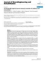
tions. Figures 3 and 4 represent the dimensionless
throughput and normalized delay values as the number
of HP STAs in the BSS increases with varying super-
frame period duration a. We see that the value of a has
a significant effect on sy stem performance with respect
to throughput and delay. Similarly, the collision prob-
ability impacts throughput and delay. Figures 3 and 4
show a surface plot that quantifies the relationship
between collision probability, number of HP users, and
the effect these parameters have on system delay and
throughput, respectively. When the system operates in
equaldurationofCPandCFP(i.e.,a = 0.5), the
throughput decreases with an increase in the number of
HP users, gradually approaching an asymptote. This can
be explained by the fact that an increasing number of
HP users create higher contention in the CP phase lead-
ing to longer backoff time and thereby a drop in
throughput and an increase in delay, as seen in Figure 4.
Inter estingly, the delay value also approache s an asymp-
tote as the number of HP users in the BSS increase
(when a = 0.5). In Figu re 3, we see that, as the number
of HP stations increases, a saturation condition at nor-
malized delay D = 1 is attained with lower values of col-
lision probability p.
With respect to Figures 4 and 5, collision probability p
is defined as the probability a given frame transmission
attempt is unsuccessful due to a collision occurring in
theCP.LookingatFigure3,onecanseethatfora
small number of HP stations, the directional derivative
dD/dp is much less than it is for a large number of HP
stations. Because the rate of change in delay increases
faster with respect to station count as collision probabil-
ity increases, a saturation condition will arise sooner in
a BSS with many high priority traffic stations if stations
begin to experience a greater number of collisions in
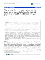
the contention period. Similarly, in Figure 4, we see how
small changes in collision probability can greatly affect
throughput as the HP station count increases. We also
see the appearance of an optimal throughput contour
along the maxima of the surface S.
3 The proposed fair MAC scheme
Providing fair channel access opportunities to both HP
and LP traffic such that adequate throughput is enjoyed
by non-real time (or LP) flows while still supporting the
QoS constraints of real-time traffic (o r HP flo ws) is the
main objective of this study, especially under scenar ios
where the bulk of network traffic is non-real time. Thus,
we have designed a scheme that would be suitable for
networks dominated by LP traffic and one that would
Sarkar and Paolini EURASIP Journal on Wireless Communications and Networking 2011, 2011:131
/>Page 7 of 15
eventually revert back to normal 802.11e functionality in
the absence of LP traffic. Before we delve into the
details of our fair MAC scheme, it is worthwhile to
examine the existing IEEE 802.11e MAC protocol.
3.1 Examining IEEE 802.11e MAC protocol
To enhance the QoS support, IEEE 802.11e introduces a
protocol called the HCF which includes two medium
access mechanisms: contention-based channel access
and controlled channel access which are referred to as
the EDCA and HCCA. With 802.11e, there are two
phases of operation within a superframe, i.e., the CP
and a CFP. Each superframe begins with a control frame
called the Beacon frame followed by the CP and then
the CFP. Figure 2 pictorially depicts a typical 802.11e
superframe.
The EDCA is used in the CP only, while the HCCA is
used in both phases. QoS polling for HCCA can take
place during CP as well. EDCF and HCCA together
support up to eight priority traffic classes (TC). Each
TC starts with a backoff after detecting the channel
being idle for an arbitration interframe space (AIFS)
period of time. The AIFS can be chosen individually for
each TC and thus provides a deterministic priority
mechanism between the TCs. Thus, a transmit opportu-
nity (TXOP) almost always is given to the TC with the
highest priority. During the CP, access is governed by
EDCF, though the hybrid coordinator (HC–generally
co-located within the AP) can initiate HCF access at
any time. During the CFP, the HC issues a QoS CF-Poll
frame to a particular station to give it a TXOP, specify-
ing the start time and maximum duration. No station
attempts to gain access to the medium at this time and
thus the station to which the CFP-poll frame was sent
has unhindered access to the medium. The HC has
available, over time, a snapshot view of the per-TC, per
station, queue length information in the cell, including
that of the AP itself. This information is sent to the HC
by stations periodically. With this i nformation, the HC
decides which station (including itself) to allocate
TXOPs during the CFP. At minimum, the following
needs to be considered: (a) priority of the TC, (b)
required QoS for the TC (low jitter, high bandwidth,
low latency, etc.), (c) queue lengths per TC, (d) queue
lengths per station, (e) duration of TXOP available and
to be allocated, and (f) past QoS seen by the TC. Thus,
even during the HCCA (as during the EDCA), TXOPs
are given to traffic of HP as well.
Figure 4 Normalized delay surface plot D = D(HP, p).
Figure 5 Dimensionless throughput surface plot S = S (HP, p).
Sarkar and Paolini EURASIP Journal on Wireless Communications and Networking 2011, 2011:131
/>Page 8 of 15
3.2 Motivating the need for a FAIR MAC scheme
Performance analysis of the QoS enh ancements of
802.11e has been demonstrated in [13-15]. Simulation
studies in [16,17] show that the EDCA provides signifi-
cant improvements for HP traffic; however, these
improvements are typically provided at the c ost of
worse performance for LP traffic. This is precisely the
problem that we identify and help mitigate in this arti-
cle. We argue that a protocol as biased as 802.11e
(toward HP traffic) can be detrimental to system perfor-
mance, especially when the traffic classification (as to
who is HP traffic and who is LP) is left to applications.
Any rational, self-serving LP application will realize that
the system “does not care” about LP traffic and might
want to falsely classify its traffic as HP traffic in pursuit
of better performance. This would potentially break-
down the entire paradigm of delivering QoS to the ones
who need it the most. Thus, we recommend in this arti-
cle that TXOPs be given to both HP and LP traffics–not
equally (that would not be fair t o the HP traffic) but at
least partially, such that LP traffic is not robbed comple-
tely of transmission opportunities in the presence of HP
traffic. We take an extremely unconventional approach
and propose that we use the CFP of a superframe to be
dedicated to transmission of LP traffic along with HP
trafficbymeansofpollingLPusersbytheHC.
Obviously the TXOP duration should not be too long
so as to increase the delay encountered by the HP users
beyond what is acceptable. The CP phase remains a
solely contention phase where HP traffic gets preferen-
tial channel acce ss over LP traffic. Figu re 6 denotes our
recommended scheme.
3.3 Our FAIR MAC scheme
Conventionally, contention-based channel access
schemes have been used for LP data transmission
whereas “polling” a nd thereby dedicated channel access
schemes have been thought of as the most appropriate
way of transmitting HP (delay-sensitive) data. It is a
well-established fact that if a MAC laye r protocol has to
cater to various types of traffic (both HP and LP), it is
imperative that it employs both contention-based and
polling channel access mechanisms. Thus, our fair MAC
scheme alternates between a contention-based channel
access mechanism, which we refer to as the CP, and a
polling-based channel access scheme, which we refer to
as the CFP as shown in Figure 6. Our system offers
channel access opportunities to both traffic types (HP
and LP) during the contention period, allocating higher
preference to the HP traffic to grab the channel over
the LP traffic. However, deviating from the norm, during
the CFP, LP traffic is included in the polling list and
thus polled by the H C along with the HP traffic. The
duration of the CFP is equally distributed to allocate
transmission time for a ll traffic flows in the network.
The polling scheme is implemented in a circular queue
such that all traffic flows gets polled almost equally. The
HC, co-located with the AP, polls every station in the
polling list starting with the traffic flow which has the
highest priority and subsequently servicing the traffic
flows on the polling list in the descending priority order
till the lowest priority traffic flow is served. The HP
flows still retain their precedence in the queue over the
LP flows. However, such dedicated service during the
CFP incentivizes LP traffic to deter from falsely classify-
ing itself as HP and thus preserves system sanctity.
During the CP, a node with packets to transmit con-
tends for channel access with a certain probability. QoS
differentiation is enforced by allowing packets in HP
queues to contend for channel access with higher prob-
ability t han packets in LP queues. We assume that
nodes are transmitting to an AP that can invoke a CFP
by issuing a poll request to one or more nodes. These
polled nodes can then transmit without any contention.
Users can classify their applications as either HP or LP.
Users are expected to take advantage of the MAC’s QoS
features by declaring their delay sensitive applications as
HP, and delay tolerant applications as LP. The AP needs
to decide what fraction of time the system will spend in
the contention and CFPs. Our protocol is very similar to
Figure 6 Proposed fair MAC scheme.
Sarkar and Paolini EURASIP Journal on Wireless Communications and Networking 2011, 2011:131
/>Page 9 of 15
802.11e’s HCF, with the CP corresponding to 802.11e’s
random access or EDCA functionality and the CFP cor-
responding to 802.11e’s polled access or HCCA func-
tionality [18]. More specifically, our system corresponds
to the HCCA/EDCA mixed mode [3] of operation.
The vast majority of moderate-rate delay sensitive HP
applications (such as VoIP and moderate resolution
video streaming) and delay tolerant LP applications (e.g.,
file transfer and em ail) can be supported by the random
access or contention functionality of 802.11e. If the
number of users with dela y sensitive traffic is relatively
large, then polling or contention-free access is inap-
propriate because of the large delay incurred in waiting
for one’s turn [17]. Therefore, from the HP user’sview-
point, it is more advantageous to operate in the CP
rather than the CFP. On the other hand, operating the
network mainly in a CP is both unfair and inefficient as
far as LP applications are concerned. It is unfair because
HP applications will obtain better throughput than LP
applications as they contend for channel access more
aggressively. It is inefficient because, even in the absence
of HP applications, LP applications are forced to be con-
servative in accessing the channel. Thus, arises the inter-
esting dilemma of how long should these CP and CFP
periods be chosen such that system performance is max-
imized. We choose to investigate this problem in our
future study.
It is also noted that polling is known to be very effi-
cient throughput-wise, but leads to large delays because
a user has to wait for his/her turn to transmit [17].
Since LP traffic is delay-tolerant, polling is an efficient
method to serve such traffic. Another consequence of
the throughput efficiency of polling is that the system
does not need to spend too much time in the CFP to
serve LP users. Thus, the negative impact of our scheme
onHPusersismild.Mostofthetimethesystemisin
the CP where HP users can enjoy good delay perfor-
mance of prioritized random access. Our incentive
mechanism exploits the difference in performance
required by HP and LP applications, to simultaneously
satisfy QoS requirements for all users. HP applications,
such as VoIP, have tight delay constraints but do not
requireveryhighthroughput. LP applications such as
file transfer have no particular delay constraints but
require relatively high throughput for reasonable session
completion times. Polling LP users during the CFP
ensures that these users are guaranteed a certain mini-
mum level of throughput, ensuring there is no motiva-
tion for LP users to falsely declare their traffic type as
HP. This in turn implies that HP users encounter
decreased interfer ence from LP users during the CP
leading to better delay performance.
It is to be noted that the duration of the CFP phase
has a significant impact on the delay encountered by the
HP traffic. This is because, the longer the CFP (to
accommodate the several LP flows in a network), the
more the time required for the system to transition into
the CP, thereby making the HP traffic wait for a longer
period of time to get an opportunity to transmit their
delay sensitive data. We intend to address this issue in a
quantitative manner in our future study. In Section 4,
we provide a numerical analysis of the above fact. We
want to emphasize that an absence of LP traf fic flow in
the network will make our scheme behave exactly in the
standard 802.11e f ashion. Thus, no undue delay will be
encountered by the HP traffic flows. In summary, the
extraopportunitytotransmitdatabytheLPflowsdur-
ing the CFP phase leads to significant increase in their
throughput with minor dent in the delay performance of
the HP flows.
4 Simulation results
We evaluated our proposed fair MAC scheme using the
network simulation platform QualNet 4.5 [18]. Our net-
work topology was comprised of several wireless stations
(or nodes) and one AP, all located within each others’
“hearing” range (i.e., every station is able to detect a
transmission from any other stationinthenetwork).
The nodes were placed in the default terrain with
default dimension settings. Each simulation has been
run for 600 s and each reported value has been averaged
over 15 runs. The si mulation results were analyzed
using the QualNet analyzer.
Table 2 enumerates the simulation parameters that we
used. It is worth mentioning that some of the system
parameters in a real network–like contention window
duration–are a function of the physical (PHY) layer pro-
tocol. We present some realistic values of such system
parameters in Table 3[19]. We were mainly interested in
analyzing the throughput and end-to-end delay charac-
teristics of our protocol in comparison to the IEEE
802.11e standard MAC protocol. We created two dis-
tinct network scenarios–network scenario I was com-
prised of a fixed nu mber of HP traffic flows (5) with an
increasing number of LP traffic flows. Specifically, we
Table 2 Simulation parameters
MAC protocol 802.11e with HCCA enabled
PHY/radio
model
802.11b-data rate 2 Mbps
Beacon interval 200 time units (TU)
CFP duration 50 TU, 160 TU
Simulation
duration
600 s
Seed 1-15
Type of traffic
source
CBR with precedence 5, 6, 7 for HP traffic CBR with
precedence 0,1 and FTP generic for LP traffic
Sarkar and Paolini EURASIP Journal on Wireless Communications and Networking 2011, 2011:131
/>Page 10 of 15
studied three distinct network configurations, namely (a)
5HPand10LPflows,(b)5HPand20LPflows,and
(c) 5 HP and 30 LP flows. Network scenario II was com-
prised of a fixed number of LP traffic flows (20) with an
increasing number of HP traffic flows. S pecifically, we
studied three distinct network configurations, namely (a)
10 HP and 20 LP flows, (b) 15 HP and 20 LP flows, and
(c) 20 HP and 20 LP flows. It is noted that in every net-
work configuration the number of LP flows is greater
than, or equal to, the number of HP flows which is con-
sistent with the kind of network scenarios which will
benefit from our MAC scheme.
4.1 Throughput performance for network scenarios I and
II
We first evaluate the throughput performance of our
scheme in comparison to the IEEE 802.11e MAC proto-
col. The total throughput of a traffic flow is the sum of
itsthroughputintheCPandCFP.Werealizethatthe
duration of the CFP will have a s ignificant impact on
the throughput performance of the scheme, especially
ontheLPtrafficflows.Weknowthatourscheme
divides the available CFP duration into equal time
chunks amongst all the traffic flows (regardless of an
HP or LP flow) present in the network at that point in
time, i.e., every data flow i n the network gets an equal
TXOP. However, priority is given to the HP traffic flows
by giving them the privilege of transmitting their data in
their respective time slots before the LP traffic flows (i.
e., HP data flows are polled before LP data flows by the
HC). We expect to see an overall increase in LP traffic
throughput in our scheme by virtue of the extra time
allocation provisioned for such traffic during the CFP.
Figures 7, 8, and 9 validate our expectation. Figures 7
and 8 reflect the HP and LP traffics throughput of our
scheme (denoted in the graph as “new HP throughput”
and “new LP thr oughput”)incomparisonwiththeHP
and LP throughput of the standard 802.11e MAC proto-
col (denoted in the graph as “old HP throughput” and
“old LP throughput”) simulated under network scenario
I with a CFP duration of 50 (time units) and 160 TU,
respecti vely. It is noted that the superframe duration (or
Beacon interval) is 200 TU in both cases. Significant
inferences include the following:
(i) In network scenario I, there is about an average
20% increase in LP traffic throughput in our scheme in
comparison to 802.11e. This is expected, since our
scheme provisions for extra time to transmit LP traffic
in the CFP which 802.11e does not. This trend is evi-
dent in both cases where the CFP duration is set to 50
and 160 TU, respectively. However, it is to be noted
that the throughput curve for LP users in both cases
(CFP = 50 and 160 TU) shows a downward trend as the
number of flows in the network increases. This can be
attributed partly due to an increase in collisions during
the CP. The major impact is however due to the thin
time slicing of dedicated time slots allocated to each LP
traffic flow as the number of flows increase in the net-
work. This is a necessary evil since we have to accom-
modate all traffic flows in the network and yet not
increase the total time duration of CFP. Also note that
we presen t the results of the worst case traffic scenario.
In our simulation, nodes havedatatosendallthetime
(constant bit rate–CBR–traffic) leading to a claim on
the time slot during CFP always. In reality, not all nodes
will have data to send at all times, thereby potentially
preventing such thin time slicing for the data carrying
nodes during CFP.
Table 3 System parameter values for three different
PHYs as specified by IEEE 802.11 standard [19]
PHY Slot time (μs) CW
min
CW
max
FHSS 50 16 1024
DSSS 20 32 1024
IR 8 μ 64 1024
Figure 7 Average throughput of each traffic type for CFP of 50 TU.
Sarkar and Paolini EURASIP Journal on Wireless Communications and Networking 2011, 2011:131
/>Page 11 of 15
Figure 9 denotes the HP and LP throughput for net-
work scenario II. This shows the same trend in through-
put increase for LP traffic as in Figures 7 and 8 for the
same reasons as explained in the previous paragraph. It
is to be noted that with an overwhelming increase in
HP traffic, LP throughput experiences a drastic decrease
in standard 802.11e but not so in our scheme as a part
of the CFP is still reserved for LP traffic transmission.
(ii) An increased duration of CFP in our scheme does
lead to an increased throughput for both HP and LP
traffic. If we increase the CFP duration to 160 TU, the
throughput of our scheme increases about 50% more
thanthestandardIEEE802.11eschemeasdepictedin
Figure 8. When the CFP duration is increased to 160
TU (superframe duration = 200 TU), there is a severe
drop in LP throughput in the standard 802.11e due to
the drastic increase in collisions during the CP which
now comprises of a small fraction of time of the total
superframe duration. This proves the relevance of CFP
duration on the network performance. However, a
longer CFP duration also increases the delay which can
be detrimental, especially for HP traffic (Figures 10 and
11).
(iii) There is a 3% reduction in HP traffic throughput
in our scheme in comparison to 802.11e. This is due to
the thinner time slicing for each HP t raffic flow during
the CFP in our scheme to accommodate the extra LP
flows within the stipulated CFP duration (for example
50 and 160 TU in our simulations). It is noted that the
increasing number of LP traffic flows also does not sig-
nificantly affect the average HP throughput, since HP
users contend for the channel more aggressively (better
EDCA parameter set than LP) than the LP users and
thus almost always gain access to the channel over LP
users. The minimal decrease in throughput of HP traffic
with an increase in the number of LP traffic flows (5 HP
+ 10 LP flows configuration versus 5 HP + 30 LP flows
networkconfiguration)inFigures7and8isattributed
to the smaller time segment devoted to each HP traffic
flow during the CFP as the number of traffic flows i n
the syste m increases. In Figure 9, the drop in HP traffic
throughput with an increase in the total number of
Figure 8 Average throughput of each traffic type for CFP of 160 TU.
Figure 9 Average throughput versus number of users for scenario II.
Sarkar and Paolini EURASIP Journal on Wireless Communications and Networking 2011, 2011:131
/>Page 12 of 15
traffic flows in the network is attributed to the more
aggressive channel con tention that occurs between the
increasing number of HP flows in the system, thereby
leading to higher collisions and hence lesser overall HP
throughput.
4.2 Delay performance for network scenarios I and II
Figures 10, 1112, and 13 show the delay performance of
HP and LP traffics, respectively, in our scheme (marked
as “new delay” on the graph) in comparison to IEEE
802.11e (marked as “old delay” on the graph) for net-
work scenarios I (Figures 10 and 12) and II (Figures 11
and 13). Our proposed scheme leads to about a 6%
increase in delay for HP traffic, as expected, since the
CFP phase is now utilized to se rve the LP traffic as well
in addition to the HP traffic, thereby leading to a longer
wait time for the system to revert back to the CP where
HP traffic can start their transmission again [20,21].
Specifically speaking, in our simulation setup (given our
data rate of 2 Mbps and CBR packet arrival), we had set
the delay bound of HP traffic to a reasonable 0.5 s for
both traffic scenarios I and II. Simulation results
depicted in Figures 10 and 11 validate that the HP delay
stays within that bound. In general, any application that
can tolerate a 7% increase in delay over a 2 Mbps data
rate channel will not be adversely affected by our pro-
posed scheme.
Moreover since majority of the flows are LP, this dete-
rioration is compensated by the almost 20% increase in
throughput of the LP traffic. Figures 12 and 13 demon-
strate the fact that the delay of LP traffic decreases con-
siderably in the proposed scheme when compared to the
standard IEEE 802.11e.
In Figure 11, as the number of HP flows increase, the
HP delay increases both in the standard 802.11e proto-
col and our scheme as well. This is due to the increased
number of collisions during the CP as HP flows in the
network increases thereby leading to longer wait time
for data delivery. In network scenario II (Figure 11), the
increase in HP delay over standard 802.11e is approxi-
mately less than 7%. Once again, i n scenarios where LP
traffic predominates, this brunt in HP delay performance
is acceptable, especially if we consider the havoc that
can be wreaked in the network if selfish LP users start
Figure 10 Average HP delay comparison between 802.11e and our scheme.
Figure 11 Average HP delay (s) versus number of users.
Sarkar and Paolini EURASIP Journal on Wireless Communications and Networking 2011, 2011:131
/>Page 13 of 15
classifying their traffic as HP and thereby wreck the
whole notion of QoS [8] in absence of a fair MAC
scheme like ours.
5 Conclusions
This article focuses on “protecting” the “underdog” or
non-real time data trafficinthefaceofthegrowing
multimedia traffic that treads the wires in recent times.
It provides analytical expressions to model the through-
put and delay of a hybrid MAC scheme akin to IEEE
802.11e followed by MATLAB simulation results which
highlight the drawback of protocols that are biased
toward protecting and guaranteeing QoS for delay intol-
erant HP traffic thereby starving the delay tolerant non-
real time flows. In addition, this article proposes a MAC
scheme which provides performance (throughput) guar-
antees to non-real time traffic in face of real-time traffic
such that they are not bandwidth starved. However, the
new MAC protocol geared toward protecting the
“underdog” traffic also aims to preserve the QoS
requirements of delay-intoleran t, HP. The performance
of the new MAC scheme is compared against the s tan-
dard IEEE 802.11e scheme using the QualNet simulation
platform. The results prove that the proposed MAC
scheme indeed boosts the throughput and delay perfor-
mance of non-real time traffic (by as high as 50%) with
a minimal dent in throughput (about 3%) and delay
(about 6%) of real-time traffic though staying within the
acceptable service range of such traffic. The QualNet
simulation results show that the performance improve-
ment of our proposed method is particularly significant
when the traffic mix comprises of mainly delay tolerant
traffic. Convention ally, using schemes like IEEE 802.11e,
LP traffic would have been sabotaged by a small popula-
tion of HP traffic which would have conventionally
squeezed the majority of network resources to ensure its
high performance. Our protocol alleviates this particular
problem and proves that a fairer scheme is indeed
Figure 12 Average LP delay comparison between 802.11e and our scheme.
Figure 13 Delay performance of LP traffic.
Sarkar and Paolini EURASIP Journal on Wireless Communications and Networking 2011, 2011:131
/>Page 14 of 15
possibleandcompletesabotageofnon-realtimetraffic
is not required to meet the demands of high priority
traffic.
Acknowledgements
This study is based upon work supported by the National Science
Foundation under Grant No. 0737048.
Author details
1
Electrical and Computer Engineering, San Diego State University, 5500
Campanile Drive, San Diego, CA 92182, USA
2
Computational Science
Research Center, San Diego State University, 5500 Campanile Drive, San
Diego, CA 92182, USA
Competing interests
The authors declare that they have no competing interests.
Received: 2 March 2011 Accepted: 12 October 2011
Published: 12 October 2011
References
1. itbusiness.ca-business advantage through Technology retrieved at http://
www.itbusiness.ca/it/client/en/home/News.asp?id=48078&PageMem=3
2. pcdistrict-news, retrieved at />dominated-by-p2p-file-sharing-review1510-16.html
3. Medium Access Control (MAC) Quality of Service (QoS) Enhancements. IEEE
802.11e Working Group, New York, P802.11e/D13.0, (January 2005)
4. IEEE Standard for Information Technology-Part 11: Wireless LAN (MAC) and
(PHY) Specifications. IEEE Std 802.11, 6/12/2007
5. Q Ni, T Turletti, QoS support for IEEE 802.11 Wireless LAN (Nova Science
Publishers, 2004)
6. A Lindgren, A Almquist, O Schelén, Quality of service schemes for IEEE
802.11 wireless LANs–an evaluation. J Mobile Netw Appl. 8(3), 223–235
(2003). doi:10.1023/A:1023389530496
7. P Garg, R Doshi, R Greene, M Baker, M Malek, X Cheng, Using IEEE 802.11e
MAC for QoS over wireless, in Proceedings of IEEE Performance, Computing,
and Communications Conference (April 2003)
8. P Nuggehalli, M Sarkar, RR Rao, QoS and selfish users: a MAC layer
perspective, in Proc of IEEE GLOBECOM, Boston, MA (November 2007)
9. D Obeid, S Sheeshia, Modeling of a polling-based access scheme for
802.11, in Proceedings of the 32nd IEEE Conference on Local Computer
Networks (2007)
10. M Sarkar, M Ray, P Nuggehalli, Evaluating a QoS-supportive MAC layer protocol
for WLANs, in Proceedings of IEEE MILCOM 2008, San Diego, CA (2008)
11. BA Venkatakrishnan, S Selvakennedy, An enhanced HCF for IEEE 802.11e
wireless networks, in Proceedings of the 7th ACM International Symposium on
Modeling, Analysis and Simulation of Wireless and Mobile Systems, Venice,
Italy (2004)
12. R Khalaf, I Rubin, throughput and delay analysis in single hop and multihop
IEEE 802.11 networks, in Proc of 3rd International Conference on Broadband
Communications, Networks and Systems, 2006 (BROADNETS 2006), San Jose,
CA, 1–9 (2006)
13. HL Truong, G Vannuccini, The IEEE 802.11e MAC for Quality of Service in
Wireless LANs, (IBM Research, Zurich Research Lab, Switzerland, 2003)
14. P Ansel, Q Ni, T Turletti, P Planete, FHCF, a fair scheduling scheme for
802.11e WLAN. INRIA Research Report 4883 (2003)
15. S Mangold, S Choi, G Hiertz, O Klein, B Walke, Analysis of IEEE 802.11e for
QoS support in wireless LANs. IEEE Wirel Commun Mag. 10(6), 40–50 (2003).
doi:10.1109/MWC.2003.1265851
16. A Grilo, M Macedo, N Nunes, A scheduling algorithm for QoS support in
IEEE 802.11e networks. IEEE Wirel Commun Mag. 10(3), 36–43 (2003).
doi:10.1109/MWC.2003.1209594
17. D Gao, J Chai, L Zhang, Physical rate based admission control for HCCA in
IEEE 802.11e WLANs, in Proceedings of the 19th international Conference on
Advanced Information Networking and Applications (AINA), Taipei, Taiwan,
479–483 (March 2005)
18. QualNet 4.5”,
19. G Bianchi, Performance analysis of the IEEE 802.11 distributed coordination
function. IEEE J Sel Areas Commun. 18(3), 535–547 (2000). doi:10.1109/
49.840210
20. R Al-Sayyed, C Pattinson, T Dacre, VoIP and database traffic co-existence
over IEEE 802.11b WLAN with redundancy, in Proceedings of the
International Conference on Computer, Information and Systems Science and
Engineering, Barcelona, Spain, 25–27 (April 2007)
21. DP Agrawal, Q Zeng, Introduction to Wireless and Mobile System, (Thomson,
Brooks/Cole, 2003) ISBN: 0534-40851-6
doi:10.1186/1687-1499-2011-131
Cite this article as: Sarkar and Paolini: A QoS guarant eeing MAC layer
protocol for the “underdog” traffic. EURASIP Journal on Wireless
Communications and Networking 2011 2011:131.
Submit your manuscript to a
journal and benefi t from:
7 Convenient online submission
7 Rigorous peer review
7 Immediate publication on acceptance
7 Open access: articles freely available online
7 High visibility within the fi eld
7 Retaining the copyright to your article
Submit your next manuscript at 7 springeropen.com
Sarkar and Paolini EURASIP Journal on Wireless Communications and Networking 2011, 2011:131
/>Page 15 of 15