Báo cáo hóa học: " Superparamagnetic iron oxide nanoparticle attachment on array of micro test tubes and microbeakers formed on p-type silicon substrate for biosensor applications" pdf
Bạn đang xem bản rút gọn của tài liệu. Xem và tải ngay bản đầy đủ của tài liệu tại đây (1.02 MB, 8 trang )
NANO EXPRESS Open Access
Superparamagnetic iron oxide nanoparticle
attachment on array of micro test tubes and
microbeakers formed on p-type silicon substrate
for biosensor applications
Sarmishtha Ghoshal
1†
, Abul AM Ansar
1
, Sufi O Raja
2
, Arpita Jana
1
, Nil R Bandyopadhyay
1
, Anjan K Dasgupta
2
and
Mallar Ray
1*†
Abstract
A uniformly distributed array of micro test tubes and microbeakers is formed on a p-type silicon substrate with
tunable cross-section and distance of separation by anodic etching of the silicon wafer in N, N-dimethylformamide
and hydrofluoric acid, which essentially leads to the formation of macroporous silicon templates. A reasonable
control over the dimensions of the structures could be achieved by tailoring the formation parameters, primarily
the wafer resistivity. For a micro test tube, the cross-section (i.e., the pore size) as well as the distance of separation
between two adjacent test tubes (i.e., inter-pore distance) is typically approximately 1 μm, whereas, for a
microbeaker the pore size exceeds 1.5 μm and the inter-pore distance could be less than 100 nm. We successfully
synthesized superparamagnetic iron oxide nanoparticles (SPIONs), with average particle size approximately 20 nm
and attached them on the porous silicon chip surface as well as on the pore walls. Such SPION-coated arrays of
micro test tubes and microbeakers are potential candidates for biosensors because of the biocompatibility of both
silicon and SPIONs. As acquisition of data via microarray is an essential attribute of high throughput bio-sensing,
the proposed nanostructured array may be a promising step in this direction.
Keywords: porous silicon, SPION, biosensor
Introduction
The promotion of silicon (Si) from being the key sub-
strate material for microel ectronic devices to a potential
light emitter emerged as a consequence of the possibility
to reduce its dimension by different techniques [ 1-3].
Extensive research in this field was triggered after the
discovery of light emission from electrochemically
etched porous Si [1]. Research on porous Si has so far
been primarily focused on microporous Si which have
average pore diameter ≤2 nm [4], exhibit room tempera-
ture photoluminescence (PL) and consequently hold
immense promise for pot ential light sources in opto-
electronic devices. However, macroporous Si with
typical pore diameters > 50 nm [4], do not exhibit PL
but has found niche applications in the field of photo-
nics [5], sensor technology and biomedicine [6,7].
Macroporous Si can potentially be used as a sensitive
transducer material for detection o f various biological
and non-biological samples as its conductivity, capaci-
tance, and/or refractive index changes upon adsorption
of molecules on its surface [8,9]. Porous Si can also be
permeated by different molecules leading to specific
properties depending on the deposited substance and
their morphology [10,11]. Because of its non-invasive
and non-radioactiv e nature, porous Si promises versatile
applications in medical diagnostics, pathogen detection,
gene identification, and DNA sequencing [11,12]. The
non-toxic behavior of porous Si makes it particularly
suitable for biosensor applications including drug deliv-
ery platform for in vivo applications [10,13]. Extensive
* Correspondence:
† Contributed equally
1
School of Materials Science and Engineering, Bengal Engineering and
Science University, Shibpur, Howrah 711103, West Bengal, India
Full list of author information is available at the end of the article
Ghoshal et al. Nanoscale Research Letters 2011, 6:540
/>© 2011 Ghoshal et al; licensee Springer. This is an Open Access article distributed under the te rms of the Creative Commons
Attribution License ( which permits unrestricted use, distribution, and reproduction in
any medium, provided the original work is properly cited.
reviews on the scope of porous Si in nanobiotechnology
have been reported in the literature [6,11,14].
For biological applications, porous Si structures with
ordered arrangement of pores having diameters approxi-
mately 1 μm are desirable for loading molecules and
drugs within the pores. Uniform macropore formation
and its dependence on the formation parameters have
been well reported [15,16]. Fewer Fabry-Perot fringes
were observed f or porous Si sensors fabricate d at higher
current densities because of greater porosity leading to
matte surface [17]. Thus, engineering a uniform structure
of macropores (approximately 1 μm in diameter), each of
which appears as a micro test tube is very desirable for
building porous Si-based biochips or biosensors. In addi-
tion, porous Si is known t o be a suitable material for
implementing an efficient and reliable surface-enhanced
Raman scattering (SERS) substrate that can be used to
detect the presence of chemical and biological molecules
[18,19]. However, to make an SERS substrate, complete
filling of the pores is undesirable as the exposed surface
area i s reduced and th us the target molecule may si mply
attach on the top surface. Nano-sized Si pillars (< 100
nm in width) with comparatively larger pores (> 1.5 μm
in diameter), appear as microbeakers on porous Si, which
provide a very convenient platform for S ERS substrate.
These microbeakers can be coated completely without
filling the pores for various bio-sensing applications.
In first part of this work, we report fab rication of
arrays of micro test tubes and microbeakers formed on
p-type Si substrate with varying pore and particle sizes.
For the micro test tubes, the pore size as well as the
inter-pore distance is typically 1 μm (approximately),
whereas, for a microbeaker the pore size exceeds 1.5 μm
and the inter-pore distance could be less than 100 nm.
Even with very thin Si walls, the microbeakers were
found to be quite stable under ambient conditions. In
the next part of this work, we successfully synthesized
and attached superparamagnetic iron oxide nanoparti-
cles (SPIONs) on the porous Si surface as well as on the
pore walls using a simple and cost-effective technique.
SPIONs have demonstrated their utility as non-invasive
molecular probes to monitor biological processes, parti-
cularly by enhancin g magnetic reson ance (MR) contrast
in MR imaging which allows monitoring of anatomical
changes as well as physiological and molecular changes
[20,21]. Therefore, such robust micro test tubes and
microbeakers formed on Si substrates with SPION
attachment promises to have immense applications in
biomedicine and biomedical sensing due to biocompati-
ble nature of both the materials [22,23].
Experimental
Macroporous Si were formed on (100) orientation, p-
type Si wafers in a specially designed teflon bath by
anodic etching in hydrofluoric acid (HF) and N, N-
dimethylformamide (DMF) solution. To obtain porous
Si with different morphology, wafers of varying resistiv-
ity (r) ranging from 0.01 to 100 Ω-cm were used. The
concentration ratios of HF/DMF, formation current
density (J), etching time (t) were also varied to obtain
porous layers having different porosity. SPIONs were
synthesized by chemical co-precipitation of ferrous and
ferric ion. Briefly, ferric and ferrous chlorides were dis-
solved in 2 M HCl in 2:1 (w/w) ratio and bare iron
oxide was obtained by addition of 1.5 M NaOH. All
steps were performed under nitrogen environment. The
formed black precipitate was washed several times by
de-ionized (DI) water through magnetic decantation to
remove excess ions. Then the precipitate was re-dis-
persed in citrate buffer of pH 4 and finally pH was
adjusted to 7 to form aqueous stable colloidal SPION
solution. The as-synthesized SPIONs were loaded onto
the desired porous Si chips by placing the porous tem-
plate in a dense aqueous solution of SPIONs under
magnetic incubation for 24 h. An external magnetic
field of 70 Gauss was applied so as to drive the SPIONs
inside the pores. This was repeated twice, first without
disturbing the system and secondly, by spraying DI
water on the chip at certain intervals during magnetic
incubation so that the particles can penetrate inside the
pores without adhering on the surf ace only, due to d ry-
ing up of the aqueous SPION solution.
Macroporous Si samples (with and without SPION
attachment) were investigated with the scanning electron
microscope (SEM). The SEM used in the present study is
a Hitachi S-3400N. The variable pressure mode of the
instrument allowed investigation of the semiconducting
samples in their natural state without the need of conven-
tional sample preparation and coating. The microscope
was operated at 20 to 30 kV and 10 to 5 mm working dis-
tance under variable pressure. Elemental analyses (qualita-
tive) were done from the energy dispersive X-ray (EDX)
spectra. Dynamic light scattering (DLS) and laser Doppler
velocimetry (LDV), for determining the hydrodynamic size
and the zeta potential respectively of the as-synthesized
SPIONs in solution, were performed on a Malvern Instru-
ments Zetasizer (5 mW HeNe laser , l = 632 nm). The
operating procedure was programmed such that there
were averages of 25 runs, each run being averaged for 15
s, with an equilibratio n t ime of 3 mi n at 25°C . The mag-
netic properties of the SPI ONs were investigated using a
superconducting quantum interference device magnet-
ometer (Model: MPMS-Quantum Design7).
Results and discussions
Formation of micro test tubes and microbeakers
The variation of pore diameter and depth of pores in
macroporous Si formed on p-type substrate with varying
Ghoshal et al. Nanoscale Research Letters 2011, 6:540
/>Page 2 of 8
current density, etching time, and HF/DMF ratio is wel l
studied [5,15,16]. We carried out a series of experiments
by varying all the formation parameters including w afer
resistivity over five orders of magnitude (0.01 to 0.05 Ω-
cm, 0.1 to 0.5 Ω-cm, 2 to 5 Ω-cm, 10, and 100 Ω-cm).
We found that macropore formatio n can be obtained
for all the wafers (except for the most conductive one),
by suitably tuning the current density and HF/DMF
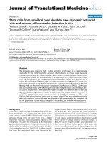
ratio as shown in Figure 1a, b, c, d. When the substrate
resistivity is reduce d to 0.01 to 0.05-Ω-cm macropore
formation could not be observed for any attempted
combination of current density and HF/DMF ratio. In
most cases, homogeneous layers with resolvable cracks
are observed as shown in Figure 1e. The findings sug-
gest that there is a critical value of substrate resistivity
(approximately 0.1 to 0.2 Ω-cm) below which no macro-
pore is obtained for our samples and these observations
are in a greement with those reported by Harraz et al.
[16].
Several models regarding the mechanism of formation
of macropores on p-type Si has so far been reported.
The depletion and field effects model proposed by
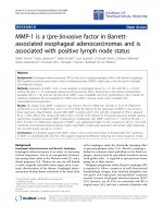
Figure 1 Top-view SEM images of macroporous Si formed on p-type substrate with different formation parameters. (a) random, wide,
and connected porous structure formed on 0.1 to 0.5-Ω-cm wafer with J = 2 mA/cm
2
, t = 30 min and HF/DMF ratio = 1:11; (b) hexagonal,
honey-comb type pore structure with narrow pore walls formed on 2 to 5-Ω-cm resistivity wafer using J = 3 mA/cm
2
, t = 60 min and HF/DMF
ratio = 1:10; (c) more-or-less regular and circular macropores on 10-Ω-cm wafer formed with J = 5 mA/cm
2
, t = 60 min and HF/DMF ratio = 1:9;
(d) widely separated pores formed with the same formation parameters as in (c) but on a 100-Ω-cm wafer; and (e) shows the formation of
cracks without any resolvable porous structure for 0.01 to 0.05-Ω-cm wafer.
Ghoshal et al. Nanoscale Research Letters 2011, 6:540
/>Page 3 of 8
Lehmann and Rönnebeck [24], the chemical passivation
model [25], th e current burst model [26], etc. have been
widely used, but a real consensus in this matter is still
awaited. However, before commenting o n the probable
mechanism governing pore formation, we first note the
major observations generated in this study with respect
to the effect of wafer resistivity on pore morphology,
which is partly reflected in the images shown in Figure
1: (1) the thickness of the macropore walls are greatly
reduced with decrease in resistivity of the starting sub-
strate; (2) for given current density and HF/DMF ratio,
inter-pore spacing increases but the pore density
decreases with increas e in resistivity of the substrate; (3)
the pore diameter also decreases with decreasing resis-
tivity (though on comparing Figure 1a with either c or d
this might seem contradictory, one has to note that the
voids seen in Figure 1a are due to more than one inter-
connected pores); (4) there is pr obably some critical
threshold resistivity (approximately 0.1 to 0.2 Ω-cm in
our case) below which no macropore can be obtained;
and (5) the geometry of the cross-section of the pore
(roughly circular or hexagonal or rectangular) can be
tailored by choosing different resis tivity wafers. In addi-
tion, we also observed, in agreement with previous
reports [5,15,16] that for a wafer of given resistivity, the
pore diameter increases almost linearly with formation
current density, whereas etching time primarily governs
the pore-depth. The effect of HF concentration and HF/
DMF ratio is relatively complex and is discussed else-
where [16]. The presence of DMF in the electrolyte
plays an important role in the formation process as it is
a very good solvent for positive charge carriers [27]. The
high concentration of DMF increases hole current at the
pore walls causing widening of the pores. Therefore, for
the low resistivity (r = 0.1 to 0.5 and 2 to 5 Ω-cm) sam-
ples, porous structure could be obtained only when both
the current density and HF/DMF ratio were maintained
at lower values.
Since the purpose of this work is to synthesize array of
micro test tubes and microbeakers of Si f or biological
applications, and not on investigating the pore forma-
tion mechanism in p-Si, we refrain from making any
assertive comments on this controversial issue. However,
from the above observations, it seems likely that charge-
transfer mechanisms similar to that of a Schottky diode
in case of anodic etching of p-Si, in which case the
holes migrate through the wafer towards the electrolyte/
Si interf ace where the space charge region is formed, as
suggested by the model of Lehmann and Rönnebeck
[24], is in all possibility the dominant mechanism. The
more-or-less square-root dependence of pore wall thick-
ness on res istivity provides initial support to this model,
whereas the variation of geometry of cross-section of
the pore is sug gestive of non-linear dissolution kinetics.
A detailed analysis of the mechanism would no doubt
depend on the systematic investigation of the role of
each formation parameter and their interdependence,
which warrants a separate investigation. Therefore, we
focus only on the samples shown in Figure 1c, d for
synthesis of microbeakers and micro test tubes.
Based on the observations reported above we synthe-
sized array of micro test tubes and microbeakers on p-Si
substrate by suitably choosing the formation parameters.
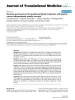
The cross-sectional SEM images shown in Figure 2a, b
clearly reveal the formation o f such micro test tubes
and microbeakers.
From the SEM image shown in Figure 2a, it is c lear
that microbeakers are formed on p-Si with distinct large
pores having diameter around 1.5 μmalongwithvery
narrow inter-pore Si walls (approximately 100 nm).
Whereas, Figure 2b reveals that a regular array of micro
test tubes with length exceeding 45 μm and inter-pore
distances around 1 μm is also obtainable on p-Si sub-
strate. From the discussion presented before, it is obvious
that the length of the pores in both cases can be con-
trolled primarily by tailoring the etching time while the
pore diameter, pore density, and consequently the inter-
pore distances are eas ily control led by varying the forma-
tion current density and HF/DMF ratio. This allows us to
synthesize arrays of microbeakers and micro test tubes
on p-Si substrate with desired lengths and cross-sections
by suitably tuning the formation parameters.
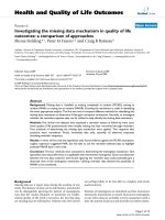
Superparamagnetic iron oxide nanoparticles
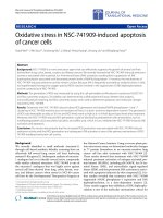
Theaveragehydrodynamicsizeoftheas-synthesized
SPIONs was measured b y DLS study. DLS analyzes
the velocity distribution of particle movement by mea-
suring dynamic fluctuations of light-scattering inten-
sity caused by the Brownian motion of the particle.
This technique yields a hydrodynamic radius, or dia-
meter, which is calculated using the Stokes-Einstein
equation from the aforementioned measurements. The
average particle size estimated in this manner is found
to be approximately 20 nm as sho wn in Figure 3. The
LDV-based zeta potential measurement of these
SPIONs using a 5 mW He-Ne, 632-nm laser revealed
that they have considerably high zeta potential value
of -50 mV, which is an evidence of high colloidal sta-
bility [28].
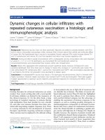
The SPIONs were investigated in terms of field cool-
ing (FC) and zero field cooling (ZFC) magnetization
curves and hysteresis loops (M-H curves). The FC/ZFC
curves obtained at different temperatures shown in Fig-
ure 4a clearly shows the presence of blocking tempera-
ture (T
B
) around 100 K. On the other hand, the lack of
hysteresis at room temperature is evident from Figure
4b. The observation of superparamagnetic b locking and
the absence of magnetic remanence directly demonstrate
Ghoshal et al. Nanoscale Research Letters 2011, 6:540
/>Page 4 of 8
that the samples are superparamagnetic at room tem-
perature [29].
SPION attachment on macroporous silicon
In an attempt to render the array of micro test tubes
and microbeakers as a potential biosensor, attempt was
made to attach the as-synthesized SPIONs onto the por-
ous template. The SEM images shown in Figure 5a, b
clearly show the presence of SPIONs attached on the
top surface of porous Si sample in the form of agglom-
erated clusters as well as inside the upper portion of the
pores.
A comparison of Figures 1c and 2b with Figure 5a
explicitly reveals t hat magnetic incubation of the bare
porous Si template has indeed resulted in SPION
impregnation/attachmen t, primarily on the surface of
the micro test tubes. From Figure 5a, b, it appears that
the nanoparticles remain attached only on the upper
portion of the pore walls with no trace at the bottom of
thepore.Wesuspectthatthishappensasaresultof
drying up of the aqueous SPION solution during the
process of magnetic incubation causing deposition of
the particles mostly on the surface of the t emplate. So,
we repeated the process with frequent addition of water
to prevent the solution from dehydrating. Figure 6a, b
shows that the simple proc ess of frequen t sprinkling of
DI water has helped in a comparatively better penetra-
tion of the SPIONs. Comparison of Figures 5b and 6b
also show that keep ing t he sol ution hydrated ha s
resulted in unblocking the pore though much of the
SPIONs still reside on the surface. Furthermore, simple
visual inspect ion of Figures 5a and 6a also suggests that
water treatment has allo wed the SPIONs to penetrate a
greater depth through the pores and attach to the walls
of Si.
Finally, to cross-verify the presence of SPIONs in the
porous Si samples, EDX spectra of the SPION-treated
sample were obtained and one such spectrum is pre-
sented in Figure 7. The EDX spectrum shows clear
peaks of Fe which establishes that the sample under
investigation does have SPIONs. It m ay be noted here
that similar experiments were performed with the
microbeakers and it was relatively easier to get the
SPIONs inside the pores because of the larger pore
sizes and smaller inter-pore distances. However, the
SPIONs tend to attach to the surface instead of
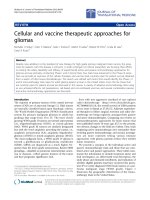
Figure 2 Cross-sectional view of macroporous Si. Showing (a) an array of microbeakers with depth approximately 8.5 μm and cross-sectional
diameter approximately 1.5 μm formed on a 100 Ω-cm wafer, with J = 5 mA/cm
2
, t = 90 min and HF/DMF ratio = 1:9 and (b) an array of micro
test tubes having length approximately 45 μm grown on a 10 Ω-cm wafer with the same parameters as mentioned in (a). The inset shown in (a)
is the top-view of the sample showing regular pores thereby revealing that the apparent irregularity of the top surface of the cross-sectional
view is introduced during cutting the sample in order to obtain the cross-sectional image. The inset shown in (b) reveals regular nature of the
pores running almost parallel to each other with pore size as well as the inter-pore distance typically approximately1 μm.
Figure 3 Size distribution of the as-synthesized SPIONs
obtained from DLS measurements shows maxima at 20 nm.
Ghoshal et al. Nanoscale Research Letters 2011, 6:540
/>Page 5 of 8
Figure 4 FC/ZFC curves obtained at different temperatures and lack of hysteresis at room temperature. (a) FC at 100 Oe and ZFC show
a bifurcation and the maximum magnetic moment in ZFC provides an estimate of the blocking temperature (T
B
), which is approximately 100 K;
and (b) M-H curve at 300 K shows no hysteresis.
Figure 5 SEM images of SPION attachment on array of micro test tubes. (a) and (b) are the cross-sectional and top view respectively,
showing substantial deposits of agglomerated particles.
Figure 6 SEM images of SPION attached micro test tubes following sprinkling of water during magnetic incubation. (a) and (b) are the
cross-sectional and top view, respectively.
Ghoshal et al. Nanoscale Research Letters 2011, 6:540
/>Page 6 of 8
penetrating into the pores when the aqueous solution
driesup.Theresultsareverysimilartotheonespre-
sented in Figures 3 and 4 and hence not presented
here. Attempts are now in progress to load the
SPIONs in micro test tubes and microbeakers along
with designed sequences of DNA at specific ensemble
of the nanopores in an attempt to upgrade the system
to a nano-designed array for specific biological
applications.
Conclusions
In summary, we have demonstrated successful fabrication
of a uniformly distributed array of micro test tubes and
microbeakers on p-type Si substrates with tunable
dimensions. Iron oxide nanoparticles, with average parti-
cle size approximately 20 nm, synthesized using chemical
co-precipitation and exhibiting superparamagnetic char-
acteristics, were attached to the surface and to the walls
of these micro test tubes and microbeakers without com-
pletely filling the pores. Such robust and cost-effective
SPION attached micro test tubes and microbeakers
formed on Si substrates have immense applications in
biomedical sensing due to biocompatible nature of both
the materials. By loading such SPIONs with designed
sequences of DNA at specific ensemble of the nanopores
may upgrade the system to a na no-designed array, the
specific details of which is presently under progress.
Acknowledgements
SG acknowledges Department of Science and Technology (DST), India for
financial support under WOS-A scheme. NRB and MR thank DST, India,
Australia-India Strategic Research Fund for providing financial support. The
authors would also like to thank ICMR (35/24/2010/BMS-NANO dated 3/11/
2010) for partial support of the research.
Author details
1
School of Materials Science and Engineering, Bengal Engineering and
Science University, Shibpur, Howrah 711103, West Bengal, India
2
Department
of Biochemistry, Calcutta University, 35 Ballygunge Circular Road, Kolkata
700019, West Bengal, India
Authors’ contributions
SG, AAMA, AJ, NRB, MR were all involved with the preparation of the micro
test tubes and microbeakers on p-Si and analyses of the results. SEM
imaging was performed by AJ and MR. SOR and ADG concentrated on the
synthesis of SPIONs, magnetic characterization, and interpre tation of results.
The magnetic incubation and loading of SPIONS were carried out by SOR,
AAMA, and SG. The idea of the present study was generated by SG, ADG,
and MR. SG and MR collated all the results and drafted the paper. ADG also
helped in drafting the final paper. All authors read and approved the final
manuscript.
Competing interests
The authors declare that they have no competing interests.
Received: 17 July 2011 Accepted: 4 October 2011
Published: 4 October 2011
References
1. Canham LT: Silicon quantum wire array fabrication by electrochemical
and chemical dissolution of wafers. Appl Phys Lett 1990, 57:1046-1048.
2. Cullis G, Canham LT: Visible light emission due to quantum size effects in
highly porous crystalline silicon. Nature 1991, 353:335-338.
3. Wilson WL, Szajowski PF, Brus LE: Quantum confinement in size-selected,
surface-oxidized silicon nanocrystals. Science 1993, 262:1242-1244.
4. Rouquerol J, Avnir D, Fairbridge CW, Everett DH, Haynes JH, Pernicore N,
Ramsey JDF, Sing KSW, Unger KK: Recommendations for the
characterization of porous solids. Pure Appl Chem 1994, 66:1739-1758.
5. Lehmann V: Trends in fabrication and applications of macroporous
silicon. Phys Stat Solidi (a) 2003, 197:13-15.
6. Batty CA: Porous silicon: a resourceful material for nanotechnology.
Recent Patents on Nanotechnology 2008, 2:128-136.
7. Saha H, Dey S, Pramanik C, Das J, Islam T: Porous silicon-based smart
sensors. In Encyclopedia of Sensors. Volume 8. Edited by: Grimes CA, Dickey
EC, Pisako MV. American Scientific Publishers; 2006:163-196.
8. Lin VSY, Motesharei K, Dancil KPS, Sailor MJ, Ghadiri MR: Porous silicon-
based optical interferometric biosensor. Science 1997, 278:840-843.
9. Reddy RRK, Chadha A, Bhattacharya E: Porous silicon based
potentiometric triglyceride biosensor. Biosens Bioelectron 2001, 16:313-317.
10. Anglin EJ, Cheng L, Freeman WR, Sailor MJ: Porous silicon in drug delivery
devices and materials. Adv Drug Deliv Rev 2008, 60:1266-1277.
11. Granitzer P, Rumpf K: Porous Si - a versatile host material. Materials 2010,
3:943-998.
12. Stewart MP, Buriak JM: Chemical and biological applications of porous
silicon technology. Adv Mater 2000, 12:859-869.
Figure 7 SEM-EDX spectrum of the sample shown in Figure 6 indicating the presence of Fe.
Ghoshal et al. Nanoscale Research Letters 2011, 6:540
/>Page 7 of 8
13. Salonen J, Kaukonen AM, Hirvonen J, Lehto VP: Mesoporous silicon in
drug delivery applications. J Pharmaceutical Sci 2008, 97:632-653.
14. Ghoshal S, Mitra D, Roy S, Majumder DD: Biosensors and biochips for
nanomedical applications: a review. Sensors and Transducers 2010,
113:1-17.
15. Vyatkin A, Starkov V, Tzeitlin V, Presting H, Konle J, Konig U: Random and
ordered macropore formation in p-type silicon. J Electrochemical Soc
2002, 149:G70-G76.
16. Harraz FA, Kamada K, Kobayashi K, Sakka T, Ogata YH: Random macropore
formation in p-type Silicon in HF-containing organic solutions: host
matrix for metal deposition. J Electrochemical Soc 2005, 152:C213-220.
17. Janshoff A, Dancil KPS, Steinem CDP, Greiner DP, Lin VSY, Gurtner C,
Motesharei K, Sailor MJ, Ghadiri MR: Macroporous p-type silicon Fabry-
Perot layers, fabrication, characterization, and applications in biosensing.
J Am Chem Soc 1998, 120:12108-12116.
18. Chan S, Kwon S, Koo TW, Lee LP, Berlin AA: Surface-enhanced Raman
scattering of small molecules from silver coated silicon nanopores. Adv
Mater 2003, 15:1595-1598.
19. Jiao Y, Koktysh DS, Phambu N, Weiss SM: Dual-mode sensing platform
based on colloidal gold functionalized porous silicon. Appl Phys Lett 2010,
97:153125-153127.
20. Thorek DLJ, Chen AK, Czupryna J, Tsourkas A: Superparamagnetic iron
oxide nanoparticle probes for molecular imaging. Ann Biomed Eng 2006,
34:23-38.
21. Kim DK, Zhang Y, Voit W, Rao KV, Kehr J, Bjelke B, Muhammed M:
Superparamagnetic iron oxide nanoparticles for bio-medical
applications. Scripta Mater 2001, 44:1713-1717.
22. Granitzer P, Rumpf K, Roca AG, Morales MP, Poelt P: Porous silicon/Fe
3
O
4
-
nanoparticle composite and its magnetic behavior. ECS Transactions 2008,
16:91-99.
23. Canham LT: Biomedical applications of porous silicon. In Properties of
porous silicon. Edited by: Canham LT. London: IEE Press; 1997:.
24. Lehmann V, Rönnebeck S: The physics of macropore formation in low-
doped p-type silicon. J Electrochem Soc 1999, 146:2968-2975.
25. Ponomarev EA, Lévy-Clément C: Macropore formation on p-type Si in
fluoride containing organic electrolytes. Electrochem Solid-State Lett 1998,
1:42-45.
26. Christophersen M, Carstensen J, Feuerhake A, Föll H: Crystal orientation
and electrolyte dependence for macropore nucleation and stable
growth on p-type Si. Mater Sci Eng B 2000, 69-70:194-198.
27. Bettotti P, Gaburro Z, Negro LD, Pavesi L: New progress on p-type
macroporous silicon electrodissolution. Mat Res Soc Symp Proc 2002, 722:
L6.7.1-L6.7.6.
28. Park JY, Choi ES, Baek MJ, Lee GH: Colloidal stability of amino acid coated
magnetite nanoparticles in physiological fluid. Mater Lett 2009,
63:379-381.
29. Bean CP, Livingston JD: Superparamagnetism. J Appl Phys 1959, 30:
S120-S129.
doi:10.1186/1556-276X-6-540
Cite this article as: Ghoshal et al.: Superparamagnetic iron oxide
nanoparticle attachment on array of micro test tubes and microbeakers
formed on p-type silicon substrate for biosensor applications. Nanoscale
Research Letters 2011 6:540.
Submit your manuscript to a
journal and benefi t from:
7 Convenient online submission
7 Rigorous peer review
7 Immediate publication on acceptance
7 Open access: articles freely available online
7 High visibility within the fi eld
7 Retaining the copyright to your article
Submit your next manuscript at 7 springeropen.com
Ghoshal et al. Nanoscale Research Letters 2011, 6:540
/>Page 8 of 8