Báo cáo hóa học: " Rolled-up tubes and cantilevers by releasing SrRuO3-Pr0.7Ca0.3MnO3 nanomembranes" ppt
Bạn đang xem bản rút gọn của tài liệu. Xem và tải ngay bản đầy đủ của tài liệu tại đây (1.69 MB, 8 trang )
NANO EXPRESS Open Access
Rolled-up tubes and cantilevers by releasing
SrRuO
3
-Pr
0.7
Ca
0.3
MnO
3
nanomembranes
Christoph Deneke
1,2*
, Elisabeth Wild
2
, Ksenia Boldyreva
3
, Stefan Baunack
2
, Peter Cendula
2
, Ingolf Mönch
2
,
Markus Simon
4
, Angelo Malachias
5
, Kathrin Dörr
3,6
and Oliver G Schmidt
2
Abstract
Three-dimensional micro-objects are fabricated by the controlled release of inherently strained SrRuO
3
/
Pr
0.7
Ca
0.3
MnO
3
/SrRuO
3
nanometer-sized trilayers from SrTiO
3
(001) substrates. Freestanding cantilevers and rolled-up
microtubes with a diameter of 6 to 8 μm are demonstrated. The etching behavior of the SrRuO
3
film is
investigated, and a selectivity of 1:9,100 with respect to the SrTiO
3
substrate is found. The initial and final strain
states of the rolled-up oxide layers are studied by X-ray diffraction on an ensemble of tubes. Relaxation of the
sandwiched Pr
0.7
Ca
0.3
MnO
3
layer towards its bulk lattice parameter is observed as the major driving force for the
roll-up of the trilayers. Finally, μ-diffraction experiments reveal that a single object can represent the ensemble
proving a good homogeneity of the rolled-up tubes.
PACS: 81.07 b; 68.60 p; 68.37.Lp; 81.16.Dn.
Keywords: rolled-up nanotubes and microtubes, freestanding membranes, ferroic oxide s, strain engineering
Background
Perovskite oxides have become a fascinating class of mate-
rials because of the wide variety of electronic properties
including an intriguing ferroic (magnetic or ferroelectric)
response for potential use in memory or sensor applica-
tions. At the same time, an epitaxial strain has been
demonstrated to massively change the fundamental prop-
erties of such oxides, i n p articular, affe cting their electron ic
behavior [1-4]. A recent sensor design includes freestand-
ing cantilevers for electromechanical devices [ 3]. An ele-
gant way to form three-dimensional structures based on
the release and d eterministic rearrangement of t wo-dimen-
sional films has been established over the last years [5-7].
An inherently strained layer stack is deposited on top of a
sacrificial layer (or substrate) and is released by selective
removal of this sacrificial layer. Due to cunning strain
design and patterning, the layer stack bends up forming
cantilevers or rolls up into nano- a nd microtubes. The
technique has been employed to form fluidic systems [8],
optical resonators [9-11], microtube l a sers [12], metamater-
ial wa veguides [13], a nd e ven microrobots [ 14,15] from
various material systems [16,17]. Due to the strain relaxa-
tion driving the bending and roll-up processes, the three-
dimensional micro-objects exhibit a unique strain state
[18], influencing the properties of the microtubes [19].
In this work, an approach for the fabrication of three-
dimensional micro-objects (freestanding cantilevers,
rolled-up microtubes) from perovskite oxides, i.e., ferro-
magnetic SrRuO
3
[SRO] known for its chemical stability
[20] and antiferromagnetic Pr
0.7
Ca
0.3
MnO
3
[PCMO], i s
reported. The di ameter of the obtained tubes varies
between 6 and 8 μm, and a preferred <100> rolling direc-
tion is observed. The etching selectivity between the SRO
film and the SrTiO
3
[STO] substrate is estimated as
1:9,100. X-ray diffraction [XRD] is carried out to evaluate
the original and final strain states. Unlike our previous
studies using μ-focus XRD [18], diffraction is carried out
for an ensemble of microtubes using a conventional sin-
gle crystal diffraction beamline setup. Results clearly
reveal the change in the strain state after roll-up, with
the PCMO layer relaxing towards its bulk lattice para-
meter, whereas the upper SRO layer is compressed.
Finally, μ-XRD is carried out on the same bea mline,
all owing for comparison of the ensemble properties with
asingleobject.Wefindthatasingletubecanrepresent
* Correspondence:
1
Laboratorio Nacional de Nanotecnologia, Rua Giuseppe Máximo Scolfaro
10000, Campinas, São Paulo, 13083-100, Brazil
Full list of author information is available at the end of the article
Deneke et al. Nanoscale Research Letters 2011, 6:621
/>© 2011 Deneke et al; licensee Springer. This is an Open Access article distributed under the terms of the Creative Commons
Attribution License ( which permits unrestricted use, distribution, and reprod uction in
any m edium, provided the original work i s properly cited.
the ensemble indicating a good overall homogeneity of
the roll-up process.
Methods
Several SRO/PCMO/SRO trilayers of various PCMO layer
thicknesses (20 to 90 nm) were grown by off-axis pul sed
laser deposition at 7 25°C on (001)-oriented STO sub-
strates. A KrF excimer laser with a wavelength of 248 nm
and a repetition rate of 2 Hz was used. All trilayers were
grown in oxygen atmospher es of 0.14 mbar for SRO and
0.3 mbar for PCMO in order to avoi d the loss of oxygen.
The etching behavior was invest igated for a 50-nm-thick
SRO layer on a STO(001) substrate. Samples were pat-
terned by optical lithogr aphy and ion etching. Two kinds
of patterns were transferred into the layer structures: (1) a
circle or triangle structure with fingers to study th e etch-
ing behavior of narrow strips (Figure 1) and (2) deep-milli-
meter-long paral lel trenches along <100>, defining the
etching direction for roll-up. After patterning, the layers
were released from the substrate by etching with HF (50
vol.%)/HNO
3
(67 vol. %)/H
2
O with a ratio of 1:1:1 [20].
The obtained structures were investigated in an NVision
40 scanning electron microscope [SEM] (Carl Zeiss, Inc.,
Oberkochen, Germany) under different tilt angles of 0°
and 54°. The height of the etched structures was measured
by a Dektak 3030 profilometer (Veeco, Mannheim,
Germany). Transmission electron microscopy [TEM] was
carried out in a Tecnai T20 (FEI, Hillsboro, OR, USA) at
200 kV on focused-ion-beam-prepared cross sections of
trilayers. Energy-dispersive X-ra y [EDX] line scans were
performed in a scanning TEM mode with a step width of
1 nm. XRD on an ense mble of rolled-up microtubes was
carried out at the D10A-XRD2 beamline of the LNLS,
Campinas (Brazil) using a 1-mm
2
beam, a wavelength of
l = 1.23985 Å, and a Pilatus 2D detector. Additionally,
μ-XRD was deducted using SU-8 compound refractive
lenses [21] on the D10A-XRD2 beamline with a focus of
100 × 9 μm
2
, with the larger beam dim ension lying along
the l ongitudin al tube a xis. The e xperimenta l procedure
was sim ilar to the procedure for μ-XRD descri bed before
by Malachias et al. [18].
Results and discussion
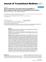
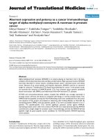
Figure 1a shows an SEM image after underetching a single
SRO layer. The ce ntral part of the pattern is a circle with
fingers in different crystallographic directions. The emer-
ging etching pattern (the initial patte rn is round; see Fig-
ure 1b) reveals that the solution etches anisotropically.
Clear etching facets in the <110> crystal direction of the
STO substrate are observed, indicating the slowest etching
direction. The <100> direction is the fastest etching direc-
tion as seen in the underetched fingers (Figure 1a, b).
From the etching time (2 min) and the mean underetching
distance in <110> directions (1.1 μm, marked for two
facets in Figure 1 a), an a verag e etching velocity of 0.55
μm/min for the <110> directions is ca lculated. Using the
height difference between the bottom and the top of the
mesa, we determine a nearly three times higher velocity of
1.45 μm/min along <001>. Since no bending or curling of
the single SRO layer is observed, the strain gradient in the
Figure 1 Etching facets and curved cantilevers.(a) Etching facets in <110> direction obtained by underetching a single SRO/STO(001) layer.
From the etching depth, a mean etching rate of 0.55 μm/min is determined. (b) Curved cantilevers fabricated from trilayers. The etching time
was chosen so that only those fingers in <010> directions are completely detached.
Deneke et al. Nanoscale Research Letters 2011, 6:621
/>Page 2 of 8
film is low as expected for the good lattice match between
cubic lattice parame ters of a
STO
= 3.905 Å and the pseu-
docubic lattice parameter a
SRO
= 3.928 Å [22,23].
To obtain rolled-up structures, the chemically inert SRO
layer w as combined with another oxide, creating a layer
stack with pronounced built-in differential stress. For this
purpose, trilayers with a functional oxide layer sandwiched
between a b ottom and a top SRO layer for protection
against the acid have been grown. For the middle sand-
wiched layer, PCMO with a pseudocubic bulk lattice para-
meter of a
PCMO
= 3.85 Å [24] has been found to work
well. Freestanding SRO/PCMO/SRO t rilayer cantilever
structures (with a total thickness of 120 nm) are shown in
Figure 1b. The underetching was deliberately stopped after
only fingers are detached in the fast etching <100> direc-
tion. The curvature of the cantilevers in Figure 1b is
around 0.0625 μm
-1
. This value indicates the relatively
large stiffness of the oxides.
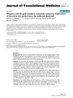
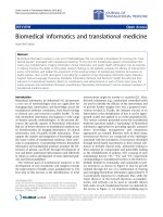
Figure 2a shows an SEM image of the opening of a
rolled-up SRO/PCMO/SRO microtube with a diameter of
6 μm.Thetubehasroughlyperformedoneandahalf
rotation on the substrate surface. Overview images of sev-
eral lithographically defined tubes of nearly 4 mm in
length are shown in Figure 2b, c. The deep trenches aris-
ing from the etching time of 20 min are oriented along a
<100> direction, which is assumed to be the natural rolling
direction because of its maximum etching speed. The
opening of the tubes is clearly observed at the beginning
of the trench, indicating a good rolling behavior. Figure 2c
shows a shorter tube section to better identify the tube on
top of the mesa. For tubes with a diameter of 6 μm and a
length of 4 mm, the aspect ratio is 1:666.
Chemical analysis and local structural investigations
have been carried out to verify that the SRO/PCMO/SRO
trilayers do not suffer a che mical or structural damage
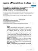
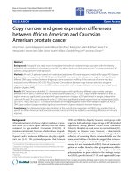
duringtheirreleasefromthesubstrate.Figure3ashows
EDX line scans for Pr and Ru taken from a trilayer before
and after the etching. No thickness reductions of the layers
have occurred within the uncertainty (approximately
1 nm) of the measurement. The SRO top layer (4 nm)
remains e ssentially unharmed by the etching. Using an
upper limit of 1 nm for the reduction of the top layer and
the applied etching time of 6 min and 10 s as well as the
above determined etching rate along <100> for STO, the
etching selectivity between the SRO layer and the STO
substrate is above 1:9,100. Careful inspection of the trilayer
cross section by high-resolution TEM indicates pseudo-
morphic growth of the trilayer (Figure 3b). The l ayer
thicknesses in this sample are 28 nm SRO/22 nm PCMO/
4 nm SRO, and the tube diameter is 6 μm as measured by
SEM.
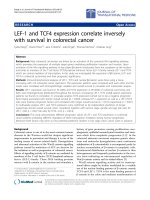
In order to investigate the strain modification between
a flat fi lm and a microtube, XRD has been performed on
a sample with long lithographically aligned tubes, using
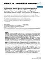
the geometry of Malachias et al. [18]. Figure 4a (inset)
shows the diffraction patterns of the flat film and an
ensemble of rolled-up microtubes in the vicinity of the
STO (002) reflection. From the peak shifts, it is obvious
that the PCMO undergoes a much larger strain change
than the SRO. For the flat film, a pseudocubic out-of-
plane lattice parameter of 3 .774 Å (3.943 Å) is derived
for the PCMO (SRO) l ayer s, respectively. The SRO value
agrees with that reported for pseudomorphic SRO/STO
(001) films an d reveals a small in-plane compression
[20,22], whereas the low value for the PCMO layer results
from the t ensile strain induced by the SRO underlayer.
For analysis, we assume a pseudomorphic trilayer accord-
ing to the TEM inspe ction. The PCMO lay er’ sout-of-
plane (in-plane) strain is -1.97% (1.42%) using the PCMO
pseudocubic bulk l attice parameter and the STO para-
meter as the in-plane parameter of the flat film. We use
the relation ε
⊥
=-2C
12
/C
11
ε
||
with the out-of-plane strain
ε
⊥
, the in-plane strain ε
||
,aswellasC
11
and C
12
as
mechanical constants for the cubic lattice, giving C
12
/C
11
~ 0.69 for PCMO. For SRO, C
12
/C
11
= 0.513 is deduced
from mechanical parameters found in the literature [25].
The diffraction pattern of the tube ensemble is calculated
[18] based on the above mentioned mechanical con-
stants, bulk lattice paramete rs, measured r adius, and
layer thicknesses. To fit the calculated curve (Figure 4a,
black solid line) to the experimental da ta, the PCMO lat-
tice parameter had to be changed to 3.855 Å. Considering
the uncertainty of the elastic parameters and the fact that
the relaxed lattice parameter of such oxide films is typi-
cally slightly larger than the bulk value, this is a realistic
result. We like to point out that the layer thickness and
the curvature of the rolled-up tube are similar to the
ones measured in TEM and SEM. From the calculation, a
longitudinal lattice parameter of a
z
= 3.905 Å is obtained,
indicating that the tubes do not relax along their longitu-
dinal axis. Using the calculated radial lattice parameter
profile, the average radial lattice parameters a
r
are esti-
mated (Figure 4b). The PCMO partially relaxes and
shows a
r
= 3.791 Å, whereas the bottom SRO layer has
nearly the same value (3.941 Å) as the flat film. The top
SRO layer becomes more compressed a fter the roll-up,
with a
r
= 3.966 Å. Such values strongly suggest that the
strain relaxation of the PCMO is the driving force for the
roll-up process.
In order t o probe the homogeneity of the ensemble, μ-
XRD w as carried out with the same sample and setup.
The small footprint allows for probing a single tube along
its axis. Figure 5 depicts the obtained diffraction data (red
circles). The diffraction pattern is compared to a calcu-
lated pattern (black line) using the parameters obtained
from the ensemble sh own in Figure 4. A good agreement
between the calculated and experimental results is
observed. We like to point out, even if the measurements
Deneke et al. Nanoscale Research Letters 2011, 6:621
/>Page 3 of 8
exhibit some noise, most of the small features from the
calculated diffraction curve are s till reproduced by the
experimental data. This indicates that the ensemble is well
represented by a single member showing a good
homogeneity of the rolled-up tubes. This conclusion is
supported by the TEM investigation that provided the cor-
rected initial layer thickness for the fitting procedure used
for the ensemble data (Figure 4). As the probing volume is
Figure 2 Rolled-up SRO/PCMO/SRO microtubes.(a) Rolled-up SRO/PCMO/SRO microtube with a diameter of 6.0 μm. (b, c) Positioned
microtubes obtained from <100> -oriented trenches defined by optical lithography. The tubes in (b) exhibit an aspect ratio of nearly 1:700.
Deneke et al. Nanoscale Research Letters 2011, 6:621
/>Page 4 of 8
extremely small by TEM, the good agreement between dif-
fraction and TEM signifies the uniformity of the rolled-up
tubes.
Conclusions
In summary, the approach of fabricating three-dimen-
sional micro-architectures by deterministic release and
rearrangement of strained films has been extended to fer-
roic oxides. Careful investigation of the etching behavior
shows a high selectivity of 1:9,100 for an SRO film against
the STO substrate. Bent-up cantilevers have been pre-
pared by releasing pseudomorphic SRO/PC MO/SRO tri-
layers fro m an STO substrate. P atterning straight long
trenches into such SRO/PCMO/SRO trilayers allows one
to fabricate well-positio ned rolled-up microtubes with
large aspect ratios. The strain states of the oxide layers
before and after roll- up have been analyzed by XRD, an d
the ense mble homog eneity has be en checked by compar-
ing the microdiffraction pattern of a single tube to the
pattern obtained from the ensemble. This approach
Figure 3 EDX analysis and bright field TEM image.(a) EDX analysis of an etched and unetched SRO/PCMO/SRO flat trilayer structure. (b)
Bright field TEM image of the flat layer stack on the substrate after etching. The measured thicknesses were used in the simulation of the XRD
spectra of the microtubes obtained from this trilayer (Figure 4).
Deneke et al. Nanoscale Research Letters 2011, 6:621
/>Page 5 of 8
Figure 4 Strain ana lysis of a flat SRO/PCMO/SRO layer.(a) Diffraction pattern of the tube ensemble around the STO (002) reflection with
experimental data (red dots) and fit (black curve, see text). The inset shows diffraction patterns of the flat film (blue, dotted line) and the rolled-
up tube (black dashed line) vs. the Bragg angle around the STO (002) peak. Note the logarithmic intensity scale. (b) Calculated tube lattice
parameters in longitudinal ( a
z
), transversal (a
t
), and radial (a
r
) directions vs. the position measured from the inside of the tube.
Deneke et al. Nanoscale Research Letters 2011, 6:621
/>Page 6 of 8
enables strain tailoring of three-dimensional oxide het-
erostructures in order to tune the magnetic, electrical, or
optical properties. The layers in a microtube experience a
strong linear radial strain gradient (Figure 4b) which ca n
be tuned continuously by varying the layer thicknesses,
whereas the longitudinal lattice parameter is roughly
fixed to that of the substrate. The effect of such kind of
strain gradient in complex fer roic oxides is rather
Figure 5 μ-XRD pattern obtained by a 100 × 9-μm
2
focused beam. The small footprint allows for probing a single tube along its a xis. The
experimental data (red circles) are compared to a calculated pattern (black line) using the parameters obtained from the ensemble measured in
Figure 4.
Deneke et al. Nanoscale Research Letters 2011, 6:621
/>Page 7 of 8
unknown and may lead to a new behavior such as a
flexoelectric effect [26]. Furthermore, cantilevers and
microtubes are less clamped by the substrate. Their thus
expected larger strain responses towards electric or ma g-
netic fields may enable an improved function for strain-
coupled systems such as two-phase magnetoelectric
heterostructures.
Acknowledgements
J. Fontcuberta is acknowledged for pointing out the potential of SRO for
this kind of experiment for its chemical inertness. We thank for the
experimental help and fruitful discussions with D. J. Thurmer, Ch. Mickel, X.
Kong, T. Dienel, and K. Nenkov. M. D. Biegalski and B. Rellinghaus are
acknowledged for providing some SRO samples and access to Tecnai T20,
respectively. Beamtime was granted by the LNLS under proposal number
D10A - XRD2 - 9948.
Author details
1
Laboratorio Nacional de Nanotecnologia, Rua Giuseppe Máximo Scolfaro
10000, Campinas, São Paulo, 13083-100, Brazil
2
Institute for Integrative
Nanosciences, IFW Dresden, Helmholtzstrasse 20, Dresden, 01069, Germany
3
Institute for Metallic Materials, IFW Dresden, Helmholzstrasse 20, Dresden,
01069, Germany
4
Institute of Microstructure Technology (IMT), Karlsruhe
Institute of Technology (KIT), Hermann-von-Helmholtz-Platz 1, Eggenstein-
Leopoldshafen, 76344, Germany
5
Departamento de Física, Universidade
Federal de Minas Gerais, CP 702, Belo Horizonte, Minas Gerais, 30123-970,
Brazil
6
Institute for Physics, Martin Luther University (MLU) Halle-Wittenberg,
Von-Danckelmann-Platz 3, Halle, 06120, Germany
Authors’ contributions
EW processed the samples and carried out a part of the analysis with the
help of CD. PC helped with the data analysis. KB and IM grew the samples
and developed the RIE etching, respectively. SB and CD carried out the SEM
and prepared the TEM sample. CD did the TEM. MS, AM, and CD carried out
the XRD and μ-XRD and did the analysis of the diffraction data. CD wrote
the manuscript with the help of AM and KD. CD, KD, and OGS conceived
and designed the experiments and supervised the work. All authors read
and approved the final manuscript.
Competing interests
The authors declare that they have no competing interests.
Received: 25 August 2011 Accepted: 7 December 2011
Published: 7 December 2011
References
1. Rata AD, Herklotz A, Nenkov K, Schultz L, Dorr K: Strain-induced insulator
state and giant gauge factor of La0.7Sr0.3CoO3 films. Phys Rev Lett 2008,
100:076401.
2. Eerenstein W, Mathur ND, Scott JF: Multiferroic and magnetoelectric
materials. Nature 2006, 442:759-765.
3. Pellegrino L, Biasotti M, Bellingeri E, Bernini C, Siri AS, Marre D: All-oxide
crystalline microelectromechanical systems: bending the functionalities
of transition-metal oxide thin films. Adv Mater 2009, 21:2377-2381.
4. Haeni JH, Irvin P, Chang W, Uecker R, Reiche P, Li YL, Choudhury S, Tian W,
Hawley ME, Craigo B, Tagantsev AK, Pan XQ, Streiffer SK, Chen LQ,
Kirchoefer SW, Levy J, Schlom DG: Room-temperature ferroelectricity in
strained SrTiO3. Nature 2004, 430:758-761.
5. Schmidt OG, Eberl K: Nanotechnology: thin solid films roll up into
nanotubes. Nature 2001, 410:168-168.
6. Prinz VY, Seleznev VA, Gutakovsky AK, Chehovskiy AV, Preobrazhenskii VV,
Putyato MA, Gavrilova TA: Free-standing and overgrown InGaAs/GaAs
nanotubes, nanohelices and their arrays. Physica E 2000, 6:828-831.
7. Schmidt OG, Schmarje N, Deneke C, Muller C, Jin-Phillipp NY: Three-
dimensional nano-objects evolving from a two-dimensional layer
technology. Adv Mater 2001, 13:756-759.
8. Thurmer DJ, Deneke C, Mei YF, Schmidt OG: Process integration of
microtubes for fluidic applications. Appl Phys Lett 2006, 89:223507.
9. Songmuang R, Rastelli A, Mendach S, Deneke C, Schmidt OG: From rolled-
up Si microtubes to SiOx/Si optical ring resonators. Microelectronic Eng
2007, 84:1427-1430.
10. Kipp T, Welsch H, Strelow C, Heyn C, Heitmann D: Optical modes in
semiconductor microtube ring resonators. Phys Rev Lett 2006, 96:077403.
11. Huang GS, Kiravittaya S, Quinones VAB, Ding F, Benyoucef M, Rastelli A,
Mei YF, Schmidt OG: Optical properties of rolled-up tubular microcavities
from shaped nanomembranes. Appl Phys Lett 2009, 94:141901.
12. Li F, Mi ZT: Optically pumped rolled-up InGaAs/GaAs quantum dot
microtube lasers. Opt Express 2009, 17:19933-19939.
13. Smith EJ, Liu ZW, Mei YF, Schmidt OG: Combined surface plasmon and
classical waveguiding through metamaterial fiber design. Nano Lett 2010,
10:1-5.
14. Zhang L, Abbott JJ, Dong LX, Kratochvil BE, Bell D, Nelson BJ: Artificial
bacterial flagella: fabrication and magnetic control. Appl Phys Lett 2009,
94:064107.
15. Solovev AA, Mei YF, Urena EB, Huang GS, Schmidt OG: Catalytic
microtubular jet engines self-propelled by accumulated gas bubbles.
Small 2009, 5:1688-1692.
16. Deneke C, Songmuang R, Jin-Phillipp NY, Schmidt OG: The structure of
hybrid radial superlattices. J Phys D-Appl Phys 2009, 42:16.
17. Mei YF, Huang GS, Solovev AA, Urena EB, Moench I, Ding F, Reindl T,
Fu RKY, Chu PK, Schmidt OG: Versatile approach for integrative and
functionalized tubes by strain engineering of nanomembranes on
polymers. Adv Maters 2008, 20:4085-4090.
18. Malachias A, Deneke C, Krause B, Mocuta C, Kiravittaya S, Metzger TH,
Schmidt OG: Direct strain and elastic energy evaluation in rolled-up
semiconductor tubes by x-ray microdiffraction. Phys Rev B 2009,
79:035301.
19. Deneke C, Malachias A, Kiravittaya S, Benyoucef M, Metzger TH,
Schmidt OG: Strain states in a quantum well embedded into a rolled-up
microtube: x-ray and photoluminescene studies. Appl Phys Lett 2010,
96:143101.
20. Gan Q, Rao RA, Eom CB, Garrett JL, Lee M: Direct measurement of strain
effects on magnetic and electrical properties of epitaxial SrRuO3 thin
films. Appl Phys Lett 1998, 72:978-980.
21. Nazmov V, Reznikova E, Mohr J, Saile V, Vincze L, Vekemans B, Bohic S,
Somogyi A: Parabolic crossed planar polymeric x-ray lenses. J
Micromechanics Microengineering 2011, 21:015020.
22. Gan Q, Rao RA, Eom CB: Control of the growth and domain structure of
epitaxial SrRuO3 thin films by vicinal (001) SrTiO3 substrates. Appl Phys
Lett 1997, 70:1962-1964.
23. Landolt H, Börnstein R: Landolt-Börnstein: Numerical Data and Function
Relationships in Science and Technology Berlin, New York, London: Springer;
1981.
24. Fujimoto M, Koyama H, Nishi Y, Suzuki T, Kobayashi S, Tamai Y, Awaya N:
Crystallographic domain structure of an epitaxial (Pr0.7Ca0.3)MnO3 thin
film grown on a SrTiO3 single crystal substrate. J Am Ceramic Soc 2007,
90:2205-2209.
25. Yamanaka S, Maekawa T, Muta H, Matsuda T, Kobayashi S, Kurosaki K:
Thermophysical properties of SrHfO3 and SrRuO3. J Solid State Chem
2004, 177:3484-3489.
26. Resta R: Towards a bulk theory of flexoelectricity. Phys Rev Lett 2010,
105:127601.
doi:10.1186/1556-276X-6-621
Cite this article as: Deneke et al.: Rolled-up tubes and cantilevers by
releasing SrRuO
3
-Pr
0.7
Ca
0.3
MnO
3
nanomembranes. Nanoscale Research
Letters 2011 6:621.
Deneke et al. Nanoscale Research Letters 2011, 6:621
/>Page 8 of 8