Báo cáo hóa học: " Influence of the oxide layer for growth of self-assisted InAs nanowires on Si(111)" ppt
Bạn đang xem bản rút gọn của tài liệu. Xem và tải ngay bản đầy đủ của tài liệu tại đây (1.6 MB, 5 trang )
NANO EXPRESS Open Access
Influence of the oxide layer for growth of
self-assisted InAs nanowires on Si(111)
Morten Hannibal Madsen
1*
, Martin Aagesen
2
, Peter Krogstrup
1
, Claus Sørensen
1
and Jesper Nygård
1
Abstract
The growth of self-assisted InAs nanowires (NWs) by molecular beam epitaxy (MBE) on Si(111) is studied for
different growth parameters and substrate preparations. The thickness of the oxide layer present on the Si(111)
surface is observed to play a dominant role. Systematic use of different pre-treatment methods provides
information on the influence of the oxide on the NW morphology and growth rates, which can be used for
optimizing the growth conditions. We show that it is possible to obtain 100% growth of vertical NWs and no
parasitic bulk structures between the NWs by optimizing the oxide thickness. For a growth temperature of 460°C
and a V/III ratio of 320 an optimum oxide thickness of 9 ± 3 Å is found.
1 Introduction
Nanowires (NWs) can potentially improve the efficiency of
devices, e.g., in photonics [1], energy storage [2], bio sen-
sing [3], and high-speed electronics [4]; and most likely
such applications will require integration with silicon-
based platforms. For some of the applications, a high den-
sity of uniform NWs without any parasitic growth is
needed. The vast majority of NW growth research has
been using Au as the collector particle. Recently, self-
assisted NW growth of both GaAs and InAs on Si(111)
has been reported for MBE directly on oxide [5-8], from
e-beam lithography defined holes in the oxide layer [9-11]
and on bare substrates [12], and also, self-assisted InAs
NW growth by MOCVD has been reported [13-15].
For this study, we concentrate on growth of self-
assisted InAs NWs, since InAs NWs have superior prop-
erties for electron transpo rt devices compared to most
other III-V materials [4]. It is furthermore of great inter-
est to combine the properties of III-V materials with the
well-established silicon technology; but this requires a
completely gold-free environment, as gold is known to be
detrimental to the opto-electronic properties of silicon.
2 Growth of self-assisted NWs
All NWs in this study were grown on 2-inch epiready
undoped Si(111) substrates using a solid source Varian
GEN II molecular beam epitaxy (MBE) system. The sub-
strates were pre-degassed at 500°C before transfer into
thegrowthchamberwheretheyweredegassedfor8
min at 630°C immediately before growth. The tempera-
ture was then lowered to 460°C, and the growth was
initiated by opening the In-shutter. The beam equivalent
pressure (BEP) was measured using an ion gauge and
growth rate calibrations were perf ormed using reflection
high-energy electron diffraction (RHEED). We used an
In BEP of 4 × 10
-8
torr, corresponding to a bulk InAs
growth rate of 100 nm/h. The As flux was turned on
during the cool down from annealing to growth tem-
perature unless otherwise stated. No pure In deposition
was neces sary for initializing growth, similar to the case
of GaAs NW growth on Si(111) [6].
The exact growth mechanism is still unclear, and both
vapor-liquid-solid [16] and vapor-solid [8] have been
reported for self-assisted InAs. The growth is initiated
either by the formation of openings in the oxide [16] or
by dissolution of oxide by group III materials at the dro-
plet/substrate interface, giving rise to a vapor-liquid-solid
growth mechanism. GaAs NW growth has been demon-
strated on SiO
2
layers with a thickness of up to 30 nm
[5], whereas a much thinner layer is required for InAs.
The key parameters to control the NW morphology,
length, and width have been reported to be the tempera-
ture and t he incoming fluxes, especially the V/III-ratio
[7,10,17]. For self-assisted InAs NWs, the pre-treatment
of the substrate was also observed to play a crucial role
for obtaining high-quality growth results. On the basis
* Correspondence:
1
Nano-Science Center, Niels Bohr Institute, University of Copenhagen, 2100
Copenhagen, Denmark
Full list of author information is available at the end of the article
Madsen et al. Nanoscale Research Letters 2011, 6:516
/>© 2011 Madsen et al; licensee Springer. This is an Open Access article distributed under the terms of the Creative C ommons
Attribution License ( /by/2.0), which permits unrestricted use, distribution, and reproduction in
any medium, provided the original work is properly cited.
of our results using different pre-treatment techniques,
we have found that the oxide layer thickness is a critical
parameter for controlling the density and yield. In gen-
era l, the NW growth can be divided into three different
types of mor phologies: (1) Growth on oxide; high den-
sity, and many tilted NWs; (2) Growth on a thin oxide
layer (approx. 1 nm); vertical and high aspect ratio NW
growth (see Figure 1B,C); and (3) Growth without oxide;
vertical NW growth, with a low density and low aspect
ratio and high probability of parasitic structures (Figure
1A). We have in particular focused on the second
regime, as it seems to be the most promising for growth
of NWs.
The high lattice mismatch (≈12%) between InAs and
Si does not suppress the growth of N Ws, and in regime
2 and 3 NWs only grow perpendicular to the substrate.
We have investigated the influence of an As flux at dif-
ferent stages in the growth process, i.e., before and dur-
ing annealing, in the cool down time to growt h
temperature, simultaneously with the In flux and a few
seconds after the In flux. No differences in the amount
of vertical NWs were found. This observation is much
different than for growths using MOCVD, where
advanced cool down procedur es has been developed for
obtaining vertical NWs [15]. A theoretical study by
Koga describes how pre-adsorption of first As and then
In assists the formation of a coherent surface and makes
it possible to grow vertical NWs [18]. The difference
between the two growth systems might be due to the
necessary pre-cracking in an MOCVD growth system,
or because of residuals from the cracking that affect the
substrat e surface. Furthermore, the gro wth temperature
is lower in MBE which g ives a lower solubility of Si in
In [19].
3 Study of the oxide layer
All substrates are covered by a native oxide layer. Using
spectroscopic ellipsometry we have measured the oxide
layer thicknesses to (14 ± 1) Å for substrates taken
_
directly from the box.
The oxide layer can be removed by hydrofluoric acid
(HF) which simultaneously passivates the surface, pre-
venting formation of a new oxide, at least f or the short
time it takes to load the sample and evacuate the cham-
ber [20]. Only areas in direct contact with the HF will
get deoxidized, making it possible t o remove the oxide
from only a part of the substrate.
To ensure the removal o f the oxide without contami-
nating the substrate, we employed Ga-assisted deoxidi-
zation [21]. SiO
2
desorbs at temperatures around 900°C
depending on the composition and background pres-
sure. Ga can react with silicon oxide via the chemical
reactions [22]
SiO
2
+4Ga→ Si + 2Ga
2
O
(1)
SiO
2
+2Ga→ SiO + Ga
2
O
(2)
and the excess Si reacts further via
SiO
2
+Si→ 2SiO
(3)
Both SiO and Ga
2
O desorb at a much lower tempera-
ture than SiO
2
. From the stoichiometry, we can expect
to remove one SiO
2
pair for every two Ga atoms, and as
the lattice spacing for SiO
2
and GaAs is almost identical,
we can use the bulk growth rate for GaAs measured
with RHEED to get an estimation of the evaporation
rate.
Using ellipsometry, we have measured the deoxidiza-
tion rate. After unloading the sample from the MBE
system, and exposing it to air, it was transferred imme-
diately to the ellipsometer. We have c orrected the data
for the small amount of reoxidization in the transfer
period. We find that the deoxidization rate is slightly
larger than expected from the stoic hiometric calcula-
tions, i.e., deposition of the amount of Ga to form a
2-nm GaAs bulk layer removes slightly more than 1-nm
SiO
2
. This is close to the result by Wright and Kroemer
who state that the deoxidization rate is slightly smaller
than the stoichiometric amount [21]. The difference
might be due to the native oxide layer consisting of
SiO
x
,wherex is a number between 1 and 2, which will
increase the desorption rate.
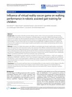
AB C
B
C
D
10 mm
A
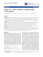
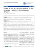
Figure 1 Nanowires grown on Ga-deoxidized substrate. (A-C)
Sideview scanning electron microscope (SEM) images of the three
different wafer positions as marked in (D), corresponding to different
oxide layer thicknesses. (D) An optical image of a full 2-inch wafer
where the oxide has only been removed in the outer part. Area (A)
is an example of growth regime 3 and areas (B, C) are from growth
regime 2 (see text). The absence of parasitic bulk structures makes
area (B) superior to area (C). White scale bars are 1 μm.
Madsen et al. Nanoscale Research Letters 2011, 6:516
/>Page 2 of 5
The Ga-deoxidization reactions are very temperature
sensitive around 800°C [21]. By e xploiting the substrate
temperature gradient when growth is carried out with-
out a backside diffuser plate, we were able to make a
partial deoxidization. The oxide layer has only been
removed in the hotter part of t he substrate, recognized
as the bright part of the optical image in Figure 1D. We
used a Ga deposition rate equivalent to a bulk growth
rate of GaAs of 300 nm/h and a temperature of 820°C,
measured with a pyrometer. The Ga flux was on for 30
min and afterward the substrate was kept at 820°C for
10 min to ensure that all Ga was re-evaporated. As con-
trol experiments, we have raised the temperature to
840°C, which completel y deoxidizes the entire substrate,
and second heat up the substrate without applying Ga,
giving no measurable deoxidization.
4 Substrate temperature gradient
A pyrometer averages the measured temperature over a
larger area; and to get a more thorough understanding
of the substrate temperature gradient, we have made
simulations using the software COMSOL Multiphysics.
The modeling is based on the geometry of the MBE
substrate mount. The MBE system is designed to handle
3-inch substrates, but for this study we use an insert to
the holder for 2-inch substrates. The substrate is heated
by thermal radiation from the backside of the holder. A
thermocoupler is placed i n the center of the heater, but
this did not affect the simulations, so instead a homoge-
nous radiation is assumed over both the substrate and
holder.
The emissivity, ε, is a measure of a given materials’
ability to emit energy by radiation. For undoped silicon,
the emissivity is highly temperature dependent, a value
of ε
Si
= 0.2 is used for the growth temperature and ε
Si
=
0.7 is used for the temperature for Ga-deoxidization
[23]. Both the holder and the insert to the holder are
made of molybdenum. For this material, the total emis-
sivity is more constant in the growth temperature
regime, and values of ε
Mo
=0.09andε
Mo
=0.12are
used for the growth and Ga-deoxidization temperature,
respectively [24].
The simulation is solved numerically in three dimen-
sions using finite-element analysis for a steady-state
system. The simulated temperature gradients on the
surface of the substrates are shown in Figure 2A and
the inset shows a surface plot of a substrate at the Ga-
deoxidization temperature. At a substrate temperature
of 460°C the temperature gradient is seen to be less
than 2°C, having little effect on the growth conditions,
whereas the gradient is 30°C at the Ga-deoxidiza-
tion temperature, affecting the local deoxidization
efficiency.
5 Comparison of deoxidization methods
For similar growth conditions, two deoxidization meth-
odsarecomparedinFigure2B,C.Thebluecurveisfor
the same growth as shown in Figure 1 where the Ga-
deoxidization method is used, whereas the red curve is
for a substrate dipped in 5% HF for 10 s and rinsed
with Millipore water (>18 MΩ resistance) for 1 min,
which forms a thin oxide layer. The average width and
heigh t of the NWs are plotted in Figure 2B,C as a func-
tion of the radial distance from the cente r of the wafer.
It shall be emphasized that the temperature gradient in
Figure 2A only applies for the Ga-deoxidized substrate
during the deoxidization process. All NWs for both
deoxidization methods are o bserved to grow perpendi-
cular to the substrate and therefore b elonging to either
regime2forathinoxidelayerorregime3inareas
where the oxide has been completely removed.
The width and length distribut ions are highly uniform
across the HF-etched substrate, whereas for Ga-deoxi-
dized it completely changes around 13 mm from the
center. This area is recognized as the bright band in Fig-
ure 1D. In this band, the length and width distributions
of the NWs are similar to the ones from the HF-etched
substrate and no parasitic bulk structures in between
the NWs are found (see Figure 1B). This growth regime
is therefore of paramount interest for self-assisted InAs
NWs. To our knowledge, the results above are the first
report of parasitic island free growth of self-assisted
NWs on non-pre-patterned substrates.
The large variation of the lengths and widths within
the same area, represented by the error bars, may be
explained by the formation of non-uniform openings in
the oxide film. Mandl et al. [16] has measured openings
in a SiO
x
layer on InAs(111)B ranging from less than
100 nm to several micrometers. In the oxide-free areas,
the morphology of the NWs is very different, and a low
density of thick and short NWs are found. This clearly
shows that the oxide layer plays a major role for self-
assisted NW growth.
Another pre-processing approach is to remove the
oxide layer completely by HF and then regrow the oxide
layer. The latter wa s done by placing the substrate on a
200°C hotplate in a fumehood, similar to the experiment
performed in [6]. For non-treated substrates. we observe
the growth of NWs in many different directions (Figure
3D), defined as growth regime 1 above, indicating a
non-epitaxial growth with respect to the substrate. For
growth on complet ely oxide-free wafers, similar to Fig-
ure 1A, only vertical NWs are observed showing that no
other (111) facets have been formed between NWs and
substrate during growth initialization (Figure 3C).
The data shown in Figur e 3 are obtained from growth
on the same substrate, by careful etching part of it at
Madsen et al. Nanoscale Research Letters 2011, 6:516
/>Page 3 of 5
different times in the pre-processing. The aforemen-
tioned temper ature gradient is m uch smaller at the
growth temperature, so the data can be compared
directly. Even a few minutes on the hotplate seems suffi-
cient to destroy the hydrogen passivation and thereby
creating an oxide layer.
The average length and width of the NWs as a function
of oxide regrowth time reach a fairly constant level almost
immediately (Figure 3A), whereas the yield of vertical
NWs drop with re-oxidization time (Figure 3B). Another
growth with re-oxidation times ranging from 2 to 26 h
indicates that the yield of vertical NWs is constant after
around 90 min. The re-growth of oxide on a hotplate
seems less favorable than the other methods investigated
above because of the high fraction of non-vertical NWs.
6 Conclusion
In conclusion, we have shown that focus should also be
put on the oxide layer thickness a nd that the substrate
preparation is important for self-assisted growth of InA s
NWs. It is found that the growth regime giving the long-
est NWs with the fewest parasitic bulk structures is
achieved for an oxide layer thickness between the native
oxide and no oxide. More precisely we have found that
an oxide layer of 9 ± 3 Å gives the best results for our
growth parameters. Moreover, several methods are used
to control the oxide layer thicknes s and we have shown
that the ultra clean method of Ga de-oxidation gives the
best results. We believe this is because the completely
impurity free environment and this therefore demon-
strates a new route toward obtaining perfect NW growth
on an entire substrate surface.
Abbreviations
BEP: beam equivalent pressure; HF: Hydrofluoric acid; MOCVD: metal organic
chemical vapor deposition; MBE: molecular beam epitaxy; NW: nanowire;
RHEED: reflection high-energy electron diffraction; SEM: scanning electron
microscopy.
Acknowledgements
The authors thank Marite Cardenas for help with the ellipsometric
measurements. We acknowledge the financial support from the Danish
Strategic Research Council, the Advanced Technology Foundation, and
University of Copenhagen Center of Excellence.
Author details
1
Nano-Science Center, Niels Bohr Institute, University of Copenhagen, 2100
Copenhagen, Denmark
2
SunFlake A/S, Nano-Science Center,
Universitetsparken 5, 2100 Copenhagen, Denmark
Authors’ contributions
MHM designed and carried out the experiments and drafted the manuscript.
MA assisted the design of the experiment, participated in the discussion of
the results and in revising the manuscript. PK participated in the discussion
of the results and in revising the manuscript. CBS and JN supervised the
study and revised the manuscript. All authors read and approved the final
version of the manuscript.
Competing interests
The authors declare that they have no competing interests.
Received: 26 May 2011 Accepted: 31 August 2011
Published: 31 August 2011
0 5 10 15 20
0
1
2
3
4
Length [μm]
Ga-deox
HF+H
2
0
0 5 10 15 20
0
500
1000
Distance from center [mm]
Width [nm]
B
C
0
10
20
30
∆T [
o
C]
0 5 10 15 20
830
o
C
800
o
C
800
o
C
A
460
o
C
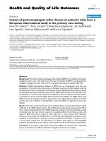
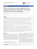
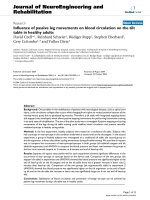
Figure 2 Temperature and NW mor phology acro ss a 2-inch
substrate. (A) Simulation of the temperature during Ga-
deoxidization and growth. Inset shows the full wafer. (B, C)
Morphology of NWs for two pre-treatment methods as a function
of the radial distance from the center. The blue curve is data from
the growth with Ga-deoxidization shown in Figure 1 and the red
curve is an HF deoxidized substrate with similar growth conditions.
The longest NWs grown on the Ga-deoxidized substrate is observed
to be at position B marked in Figure 1. The growth time is 60 min
and an As
4
BEP of 1.30 × 10
-5
torr, corresponding to a V/III-ratio of
320 has been used for both substrates.
0 1 2
native
0
1
2
3
Oxide re
g
rowth time [hr]
Length [μm]
0
100
200
300
0 1 2
0
100
Oxide re
g
rowth time [hr]
Vertical NWs [%]
native
Width [nm]
A
B
C
D
C
D
C
D
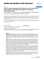
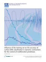
Figure 3 Regrowth of oxide on a 200°C hotplate. (A) Length
and width of NWs as a function of regrowth time for the oxide
layer. (B) Percentage of vertical NWs, indicating an epitaxial relation
to the substrate. The As
4
flux is 1.30 × 10
-5
torr, corresponding to a
V/III-ratio of 320, and the growth time is 30 min. The point to the
left marked with a C is without any re-oxidization treatment. A
typical SEM image for this regime is shown in (C). (D) SEM image of
growth on a native oxide layer marked with a D in the graphs.
Scale bars are 1 μm.
Madsen et al. Nanoscale Research Letters 2011, 6:516
/>Page 4 of 5
References
1. Yan R, Gargas D, Yang P: Nanowire photonics. Nat Photon 2009, 3:569.
2. Chan CK, Peng H, Liu G, McIlwrath K, Zhang XF, Huggins RA, Cui Y: High-
performance lithium battery anodes using silicon nanowires. Nat
Nanotechnol 2008, 3:31.
3. Patolsky F, Zheng G, Lieber CM: Nanowire-Based Biosensors. Anal Chem
2006, 78(13):4260.
4. Milnes A, Polyakov A: Indium arsenide: a semiconductor for high speed
and electro-optical devices. Mater Sci Eng B 1993, 18(3):237.
5. Fontcuberta I, Morral A, Colombo C, Abstreiter G, Arbiol J, Morante JR:
Nucleation mechanism of gallium-assisted molecular beam epitaxy
growth of gallium arsenide nanowires. Appl Phys Lett 2008, 92(6):063112.
6. Krogstrup P, Popovitz-Biro R, Johnson E, Madsen MH, Nygård J,
Shtrikman H: Structural Phase Control in Self-Catalyzed Growth of GaAs
Nanowires on Silicon (111). Nano Lett 2010, 10(11):4475.
7. Koblmüller G, Hertenberger S, Vizbaras K, Bichler M, Bao F, Zhang J,
Abstreiter G: Self-induced growth of vertical free-standing InAs
nanowires on Si(111) by molecular beam epitaxy. Nanotechnology 2010,
21:J5602+.
8. Hertenberger S, Rudolph D, Bolte S, Döblinger M, Bichler M, Spirkoska D,
Finley JJ, Abstreiter G, Koblmüller G: Absence of vapor-liquid-solid growth
during molecular beam epitaxy of self-induced InAs nanowires on Si.
Appl Phys Lett 2011, 98(12):123114.
9. Hertenberger S, Rudolph D, Bichler M, Finley JJ, Abstreiter G, Koblmüller G:
Growth kinetics in position-controlled and catalyst-free InAs nanowire
arrays on Si(111) grown by selective area molecular beam epitaxy. J Appl
Phys 2010, 108(11):114316.
10. Plissard S, Dick KA, Larrieu G, Godey S, Addad A, Wallart X, Caroff P: Gold-
free growth of GaAs nanowires on silicon: arrays and polytypism.
Nanotechnology 2010, 21(38):385602.
11. Plissard S, Larrieu G, Wallart X, Caroff P: High yield of self-catalyzed GaAs
nanowire arrays grown on silicon via gallium droplet positioning.
Nanotech-nology 2011, 22(27) :275602.
12. Dimakis E, Lhnemann J, Jahn U, Breuer S, Hilse M, Geelhaar L, Riechert H:
Self-assisted nucleation and vapor-solid growth of InAs nanowires on
bare Si(111). Cryst Growth Des 2011, 11.
13. Mandl B, Stangl J, Mårtensson T, Mikkelsen A, Eriksson J, Karlsson LS,
Bauer G, Samuelson L, Seifert W: Au-Free Epitaxial Growth of InAs
Nanowires. Nano Lett 2006, 6:1817.
14. Dayeh SA, Yu ET, Wang D: Growth of InAs Nanowires on SiO2 Substrates:
Nucleation, Evolution, and the Role of Au Nanoparticles. J Phys Chem C
2007, 111(36):13331.
15. Tomioka K, Motohisa J, Hara S, Fukui T: Control of InAs Nanowire Growth
Directions on Si. Nano Lett
2008, 8(10):3475.
16. Mandl B, Stangl J, Hilner E, Zakharov AA, Hillerich K, Dey AW, Samuelson L,
Bauer G, Deppert K, Mikkelsen A: Growth Mechanism of Self-Catalyzed
Group III?V Nanowires. Nano Lett 2010, 10(11):4443.
17. Colombo C, Spirkoska D, Frimmer M, Abstreiter G, Fontcuberta I, Morral A:
Ga-assisted catalyst-free growth mechanism of GaAs nanowires by
molecular beam epitaxy. Phys Rev B 2008, 77(15):155326.
18. Koga H: Effect of As preadsorption on InAs nanowire heteroepitaxy on Si
(111): A first-principles study. Phys Rev B 2009, 80(24):245302.
19. Olesinski RW, Kanani N, Abbaschian GJ: Bulletin of alloy phase diagrams.
In Bulletin of Alloy Phase Diagrams. Volume 6. American Society for Metals;
1985.
20. Utani K, Suzuki T, Adachi S: HF-and NH4OH-treated (111)Si surfaces
studied by spectroscopic ellipsometry. J Appl Phys 1993, 73:3467.
21. Wright S, Kroemer H: Reduction of oxides on silicon by heating in a
gallium molecular beam at 800 degC. Appl Phys Lett 1980, 36:210.
22. Cochran CN, Foster LM: Vapor Pressure of Gallium, Stability of Gallium
Suboxide Vapor, and Equilibria of Some Reactions Producing Gallium
Suboxide Vapor. J Electrochem Soc 1962, 109(2):144.
23. Timans PJ: Emissivity of silicon at elevated temperatures. J Appl Phys
1993, 74:6353.
24. Matsumoto T, Cezairliyan A, Basak D: Hemispherical Total Emissivity of
Niobium, Molybdenum, and Tungsten at High Temperatures Using a
Combined Transient and Brief Steady-State Technique. Int J Thermophys
1999, 20:943.
doi:10.1186/1556-276X-6-516
Cite this article as: Madsen et al.: Influence of the oxide layer for
growth of self-assisted InAs nanowires on Si(111). Nanosc ale Research
Letters 2011 6:516.
Submit your manuscript to a
journal and benefi t from:
7 Convenient online submission
7 Rigorous peer review
7 Immediate publication on acceptance
7 Open access: articles freely available online
7 High visibility within the fi eld
7 Retaining the copyright to your article
Submit your next manuscript at 7 springeropen.com
Madsen et al. Nanoscale Research Letters 2011, 6:516
/>Page 5 of 5