Báo cáo hóa học: " Power allocation, bit loading and sub-carrier bandwidth sizing for OFDM-based cognitive radio" pot
Bạn đang xem bản rút gọn của tài liệu. Xem và tải ngay bản đầy đủ của tài liệu tại đây (1.02 MB, 24 trang )
RESEARCH Open Access
Power allocation, bit loading and sub-carrier
bandwidth sizing for OFDM-based cognitive radio
Vinay Thumar
1*
, Taskeen Nadkar
1
, Tej Gopavajhula
1
, Uday B Desai
2
and Shabbir N Merchant
1
Abstract
The function of the Radio Resource Management module of a Cognitive Radio (CR) system is to evaluate the
available resources and assign them to meet the Quality of Service (QoS) objectives of the Secondary User (SU),
within some constraints on factors which limit the performance of the Primary User (PU). While interference
mitigation to the PU spectral band from the SU’s transmission has received a lot of attention in recent literature;
the novelty of our work is in considering a more realistic and effective approach of dividing the PU into sub-bands,
and ensuring that the interference to each of them is below a specified threshold. With this objective, and within a
power budget, we execute the tasks of power allocation, bit loading and sizing the sub-c arrier bandwidth for an
orthogonal frequency division multiplexing (OFDM)-based SU. After extensively analyzing the solution form of the
optimization problems posed for the resource allocation, we suggest iterative algorithms to meet the
aforementioned objectives. The algorithm for sub-carrier bandwidth sizing is novel, and not previously presented in
literature. A multiple SU scenario is also considered, which entails assigning sub-carriers to the users, besides the
resource allocation. Simulation results are provided, for both single and multi-user cases, which indicate the
effectiveness of the proposed algorithms in a CR environment.
Keywords: cognitive radio, OFDM, interference mitigation, power allocation, bit loading, sub-carrier bandwidth
sizing
I. Introduction
A new paradigm, called Cognitive Radio (CR), has
emerged in the field of wireless communica tion, to alle-
viate the imbalance between spectrum allocation and its
use [1,2]. CR entails the temporary usage of unused por-
tions of the spectrum (spectrum holes or white spaces),
owned by the licensed users (Primary Users–PUs),tobe
accessed by unlicensed users (Secondary Users–SUs).
Built on the platform of software-defined radio (SDR),a
CR node is rendered reconfigurable: the SDR allows the
operating parameters such as frequency range, modula-
tion type or output power to be reconfigured in soft-
ware, without making any alteration in the hardware [2].
It is anticipated that the Next-Generation (xG) commu-
nication networks will be based on CR [2]. These net-
works will provide high bandwidth to mobile users via
heterogenous wireless architectures and dynamic spec-
trum access techniques. Besides the tasks of spectrum
sensing, spectrum allocation, spectrum sharing and
spectrum mobility, one of the key functions of CR nodes
in spectrum-aware xG networks is spectrum utilization.
The spectrum utilization function entails efficient Radio
Resource Management (RRM), the aim of which is to
evaluate the available resources (power, time slots, band-
width, etc) and assign them to meet the QoS objectives
of the SU, within some constraints on factors (typically
interference) which limit the performance of the PU [3].
Furthermore, for optimum spectrum utilization it is
necessary to be adaptive to, one or more, time-varying
characteristics of the system, such as the wireless chan-
nel state, number of users, QoS requirements, etc.
OFDM is a widely-deployed multi-carrier modulation
technology for various wireless application segments,
besides being a popular choice for CR. Other than its
ability to handle multi-path fading and inter-symbol
interference, it offers flexibility of resource allocation
(power, constellation size and bandwidth) o f its indivi-
dual sub-carriers. The two main impairments in OFDM
are inter-symbol interference (ISI) and inter-carrier
* Correspondence:
1
Indian Institute of Technology, Bombay, 400076, India
Full list of author information is available at the end of the article
Thumar et al. EURASIP Journal on Wireless Communications and Networking 2011, 2011:87
/>© 2011 Thumar et al; licensee Springer. This is an Open Access article distributed under the terms of the Creative Commons
Attribution License ( which pe rmits unrestricted use, distribution, and reprodu ction in
any medium, provided the original work is properly cited.
interference (ICI) [4]. ISI is m itigated by the addition of
a guard interval (G I) which should be longer than that
delay spread of the channel (also known as the cyclic
prefix, since it is a cyclic copy of the original symbol).
Thelossoforthogonalitybetweenthesub-carriersof
OFDM due to its sensitivity to frequency offsets results
in ICI. Frequency errors which occur due to local oscil-
lator errors can be easily compensated by frequency
tracking, while those due to Doppler spread are poorly
compensated for.
In conventional OFDM systems, optimum power allo-
cation that maximizes the channel capacity under a total
power budget is water-filling [4]. However, when OFDM
is used for the SU system in a CR scenario, it’sside-
lobes causes interference to the PUs, limiting their per-
formance. The Federal Communications Commission’s
(FCC) Spectrum Policy Task Force has recommended a
metric called the interference temperature which when
exceeded causes harmful interference to the PU band.
The issue of interference mitigation in the PU band is
receiving increasing attention in recent literature [5-14].
In an OFDM-based SU system, the amount of interfer-
ence to the PU band depends on the SU’s sub-carrier
parameters (power and bandwidth), the spectral distance
between the SU’s sub-carriers and the PU band, as well
as the channel between the SU and PU. Bit loading (or
constellation sizing or modulation) for CR imposes an
additional condition that a given performance should be
achieved in every sub-carrier. The SNR gap is used to
measure the reduction of SNR (signal to noise ratio)
with respect to the capacity; it depends on the target
error probability required in every sub-carrier when it
carries log
2
(M ) bits per symbol, either QAM (quadra-
ture amplitude modulation) or PSK (phase shift keying)
modulated [15]. The sub-carrier bandwidth selection in
OFDM is a trade-off between increasing the sub-carrier
bandwidth to decrease the ICI, and reducing the band-
width to mitigate ISI [16,22]. In CR, the interference to
the PU band is a function of the SU sub-carrier band-
width; the optimum sub-carrier bandwidth is, therefore,
the one that maximizes the SU throughput while miti-
gating the PU interference.
The contribution of this paper is in developing a ho l-
istic resource allocation scheme for an OFDM-based
CR, which includes power allocation, bit loading and
sub-carrier bandwidth sizing. First, we address each of
these issues as independent problems; the objective
being - maximization of the SU’sthroughputundera
power budget and an interference constraint for the PU
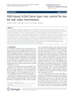
spectral band. Then, a joint optimization problem is for-
mulated, which encompasses the aforementioned indivi-
dual problems (Figure 1). In each case, we consider a
realistic and efficient strategy, wherein the PU is divided
into sub-bands, and the interference to each of its sub-
bands is separately constrained. In case of both single
and multi-user scenarios, the optimization problems are
difficult to solve due to either non-linearity of equations
or their combinatorial nature. A rigorous examination
of their solution form motivates the development of
computationally simple, sub-optimum algorithms for the
problems posed. The proposed strategies for power allo-
cation and bit loading outperform those which have
been previously presented in literature; while those for
adaptive sub-carrier sizing for CR, are novel and have
not been proposed earlier. (We would like to note here
that the titles of some works of literature on CR suggest
adaptive sub-carrier bandwidth/allocation [11,23,24],
which actually refers to the assignment of sub-carriers
to users in a multiple SU scenario, and not sub-carrier
bandwidth sizing.)
To detail the proposed scheme, the paper has been
organized as follows: Section 30 presents related litera-
ture. Section 31 describes the system model and com-
muni cation scenario for a single SU. Sections 33, 35, VI
and VII describe the power allocation, bit loading, sub-
carrier bandwidth sizing and combined optimization
problems, respectively. Likewise, SectionsVIII-XII are
dedicated to the corresponding multiple SU situation. It
is followed by a complexity analysis of each of the pro-
posed algorithms, in Section XIII. Section XIV presents
exhaustive simulation results and their discussion, while
Section XV concludes the paper.
II. Related work
A. Power allocation
Weiss et al. [5] have characterized the mutual interfer-
ence between the PU and SU in an OFDM-based CR.
Bansal et al. [6] have formulated the power allocation
problem for a single SU with the objective of maximiz-
ing it’s throughput while maintaining the interference to
the entire PU band below a threshold, however , without
a total power constraint. The model of Wang et al. [7]
considers a single SU and multiple P Us; the system
bandwidth is divided into sub-channels, and different
PUs co-exist with the SU on each sub-channel. A path-
Figure 1 Resource allocation for OFDM-based cognitive radio.
Thumar et al. EURASIP Journal on Wireless Communications and Networking 2011, 2011:87
/>Page 2 of 24
loss model is used between the SU and PU to determine
the peak power constraint of e ach sub-channel. Addi-
tionally, a total power constraint is included and the
objective is to maximize the SU’s capacity. The algo-
rithm used is called iterative partitioned water-filling.
The system model of Wang et al. [8] is similar to that
of [7], however, they have additionally considered the
side-lobe power in each SU sub-channel, contributed by
the neighboring sub-carriers, in the optimization
problem.
The situation for multiple SUs is more challenging,
since it involves allotment of sub-carriers to users,
besides power allocation, under the specified constraints.
Münz et al. [25] and Jang et al. [26] have suggested stra-
tegies for multi-us er powe r allocation with the objective
of maximizing t he total data rate. Shen et al. [27] have
proposed power allocation with proportional fairness
among the users. Wong et al. [23] and Kivanc et al. [24]
have provided bit-loading and power allocation algo-
rithms to minimize the total transmit power in the
multi-user scenario.
Power allocation for multiple SUs in the CR scenario
has also received consi derable attention in recent litera-
ture. Chengshi et al. [9] have performed multi-user
water-filling for CR. More recently, Shaat et al. [10] and
Bansal et al. [11], have presented a Lagrangian formula-
tion for maximizing the sum capacity of multiple SUs
subject to a power budget and PU interference con-
straints. Since the combinatorial optimization problem
is computationally complex, both refere nces have pro-
posed sub-optimal schemes. First the users are allocat ed
SU sub-carriers based on the best channel conditions,
and the interference constrained maximum power limit
on each SU sub-carrier is computed; then a cap-limited
water-filling is executed [10]. On the other hand, the
users are allocated sub-carriers based on the channel-to-
noise ratio (CNR), and the Lagrangian formulation is
used to maximize the sum capacity of the SUs under
the PU interference constraints [11].
B. Bit loading
Two main clas ses of bit loading problems are: rate max-
imization (RM)–maximizing the data rate within a
power budget; and margin maximization (MM)–mini-
mizing power consumption given a target data rate [28].
The implementation of bit loading algorithms in litera-
ture fall into two broad categories. The first category of
algorithms use numerical methods that employ Lagran-
gian optimization, result ing in real numbers for the bit
loading ([23,29,30]). However, for practical constellation
sizing, the number of bits allocated per sub-carrier is
restricted to integer values, which imposes a combina-
torial structure in the loading optimization problem.
The second category of algorithms employ a discrete
greedy method in order to obtain optimum integer bit
allocation results ([31-38]). Bit loading for a multi-user
OFDM scenario has been addressed by Wong et al. [23]
and H uang et al. [39] for MM and RM problems,
respectively.
In the CR context, the following work exi sts in litera-
ture: Tang et al. [12] have formulated a bit loading pro-
blem for multiple SUs, which is based on maximizing
total system throughput under interference power con-
straint to PUs, individual datarateconstraintsforthe
SUs and tot al transmission power constraint. Cheng et
al. [13] have used a game-theoretic approach to formu-
late a transmit power control game for CR, which jointly
solves the b andwidth allocation, bit loading and power
allocation problems. Budiarjo et al. [14] have used the
Fischer and Huber algorithm [37] for bit-loading for a
single SU, followed by Raised Cosine windowing to miti-
gate the side lobe interference to the PU.
C. Sub-carrier bandwidth sizing
The most significant literature on sub-carrier bandwidth
sizing is summarized in this section. Das et al. [16,17]
have proposed an approach for adaptive bandwidth for
sub-carriers for single user OFDM and a multi-user sce-
nario [18]. Zhang and Ma [19] have also proposed the
implementation of variable sub-carrier bandwidth fo r a
multi-user OFDM down-link scenario. Steendam and
Moeneclaey [20], Harvatin and Ziemer [21], and Tufves-
son and Maseng [22] have demonstrated the impact of
varying the sub-carrier bandwidth on the system perfor-
mance in a time and frequency-sel ective channel (either
in terms of interference power or in terms of BER), but
do not discuss the gains from dynamically adjusting the
bandwidth.
We infer from our analysis of the aforementioned
works in literature, that most of the power allocation
algorithms for CR have co nsidered the entire PU band
as one, for characterizing the in terference. This is not as
effective as the proposed strategy of dividing the PU
into sub-bands, and separately mitigating the interfer-
ence to each of them. While the authors of [10] have
characterized the interference to each PU sub-band, in
their problem solution, only the spectrally closest PU
band is considered for the interference constraint.
Moreover, the channel gain from different SUs to each
PU sub-band has been ignored in their formulation. In
[11], a brute-force combinatorial approach is executed
for power allocation, which has high computational
complexity. In the proposed power allocation algorithm,
we have jointly considered interference mitigation to
each PU sub-band, within the power budget, while max-
imizing the throughput of the single SU, or the sum
throughput in case of multiple SUs. The approach
attempts to strike a balance between performance
Thumar et al. EURASIP Journal on Wireless Communications and Networking 2011, 2011:87
/>Page 3 of 24
optimization and computational complexity. Similar
considerations are applied for PU interference mitigation
in the proposed bit loading and sub-carrier bandwidth
sizing algorithms.
III. System Model and Com munication Scenario:
Single SU
In the current model, a single SU transceiver is co nsid-
ered, and a PU exists in its radio range (Figure 2).
OFDM is the communic ation technology of the SU, the
use of which divides the available bandwidth into fre-
quency-flat sub-carriers. When the PU claims a portion
of the spectrum, the SU nulls the corresponding sub-
carriers. Let N
s
be the number of active sub-carriers for
the SU. The transmission opportunity is detected by the
SU in the spectrum sensing phase of its cognitive cycle
[1]. The channel power gain of the ith sub-carrier on
the link between the SU transmitter (Tx) and receiver
(Rx) is denoted by h
i
. To efficiently control the interfer-
ence to the PU, the PU spectrum is divided into N
p
sub-bands of equal width, and the gain of the jth sub-
band from the SU Tx to the PU Rx i s given by g
j
.Inthe
present work, we have considered an immobile SU,
resulting in no Doppler spread. It is assumed that the
frequency offset due to any other source is compensated
[40], and consequently we ignore the effect of I CI. The
mutual interference model between the PU and SU is
assumed [5].
Resource allocation strategies in CR require that the
channel state information (CSI) be known to the SU Tx.
It is assumed that the SU Rx estimates the channel by
measuring the received power of the pilot signals sent
by the transmitter, and the CSI is fed back to the trans-
mitter [41]. A robust and low-complexity protocol can
be used for the feedback. A block fading propagation
channel is assumed where the channel remains constant
during the resource allocation and transmission process.
The channel sensing and feedback is done once per
coherence time. Estima ting the channel between the PU
Tx and SU Rx, as well as that between the SU Tx and
PU Rx, is more chall enging, and entails the use of blind
estimation techniques [41].
The maximum achievable throughput of the SU, in
bits/sec, is given by [16]
C =
1
Tg +
1
B
N
s
i
=1
log
2
1+
P
i
h
i
σ
2
i
(1)
in which B is the sub-carrier bandwidth, T
g
is the dura-
tion of the guard interval, and P
i
is the power allocated to
the ith SU sub-carrier.
σ
2
i
= σ
2
+ J
i
, where s
2
is the Addi-
tive White Gaussian Noise (AWGN) variance, and J
i
is the
interference from the PU on the ith SU subcarrier. J
i
depends on the power spectral density (PSD) of the PU
and the channel gain between the PU Tx and SU Rx.
The interference from the SU on the j
th
PU sub-band
is formulated as
I
j
= g
j
N
s
i=1
P
i
j
th
PUband
Sinc
2
[(f − f
i
)T
s
]
(2)
where
T
s
= T
s
+ T
g
.
T
s
is the total length of the symbol
after adding the guard interval, T
s
is the length of the sym-
bol without the guard interval, and f
i
represents the center
frequency of the ith subcarrier. Sinc(x) is the mathematical
function commonly defined by Sin(πx)/(πx).
IV. Power allocation
In the power allocation problem, our objective is to
maximize the SU throughput under a total node power
constraint P
t
, in such a way that the interference to the
jth PU sub-band is less than a threshold
I
j
th
.
I
j
th
= T
j
th
BW
j
,
where
T
j
th
is the interference temperature limit for the j
th
PU sub-band and BW
j
is its bandwidth. For simplicity of
representation, we assume that the interference thresh-
old is the same for all PU sub-bands and is denoted by
I
th
. The optimization problem can stated as
Problem P1
obj = max
C
P
i
(3)
subject to
I
j
≤ I
th
∀
j
(4)
N
s
i
=1
P
i
≤ P
t
(5)
P
i
≥
0
(6)
The Lagrangian for the above is formulated as
L(P
i
, λ
j
, μ, β
i
)=
N
s
i=1
log
2
1+
P
i
h
i
σ
2
i
−
N
p
j
=1
λ
j
(I
j
− I
th
)
(7)
SU Tx
PU
SU - SU link
SU
I
th
g
1
g
2
g
3
h
1
h
2
h
3
…
…
SU - PU link
SU PU
SU Rx
Figure 2 System model for a single secondary user.
Thumar et al. EURASIP Journal on Wireless Communications and Networking 2011, 2011:87
/>Page 4 of 24
−μ
N
s
i=1
P
i
− P
t
+
N
s
i=1
β
i
P
i
(8)
The multiplicative factor 1/(Tg +1/B)intheexpres-
sion for C, is a constant in the power optimization pro-
blem, and is ignored in the above expression and all the
subsequent analysis in this section. l
j
, μ and b
i
are the
Lagrangian multipliers. The problem is a convex optimi-
zation problem, and Karush-Kuhn-Tucke r (KKT) condi-
tions [42] are applied to find the optimum solution.
Also, since we require P
i
≥ 0, b
i
is substituted as 0, due
to the complementary slackness condition [42]. The
optimum power allocation is given by [43] (which refers
to our own previous work)
P
∗
i
=max
⎛
⎝
1
N
p
j=1
λ
j
g
j
Q
j,i
+ μ
−
σ
2
i
h
i
,0
⎞
⎠
(9)
in which
Q
j,i
=
j
th
PUband
Sinc
2
[(f − f
i
)T
s
]
(10)
λ
j
≥ 0, μ ≥
0
(11)
Though the above solution looks like water-filling, it is
different from the conventional water-filling technique in
the f act that each SU sub-carrier has a different water level.
We would like to note here t hat the problem formula-
tion in [7] and [8] appear similar to the above problem
(P1). However, the system model of the current work and
that of the aforementioned references are significantly dif-
ferent–while the former considers the system bandwidth
to be frequency division multiplexed by the PU and SU,
the latter assumes the two entities to be spatially separate
but occupying the same spectrum. In the problem formu-
lation of [7], the inequality constraints are decoupled,
making the problem simpler to solve using either an
exhaustive search-based a pproach or an iterative parti-
tioned water-filling. On the other hand, in the formulation
of [8], the inequality constraints are coupled by the use of
dependent variables. Its solution involves segregating the
equality (binding) and inequality (non-binding) constraints
for the given power budget using a search-based approach
and computing the optimal solution from the equality
constraints. This technique has a high computationally
complexity. The proposed method attempts to find a low-
complexity sub-optimum solution after a detailed analysis
of the solution form.
As the optimization problem (P1)isconvexwithlin-
ear constraints, at the optimum point some constraints
are binding, while the others are non-binding. If the
power budget of the SU (P
t
) is too small, then that will
be a bi nding constraint and all interference constraints
are non-binding; the corresponding Lagrange multipliers
(l
j
) are zero and the solution looks like that of conven-
tional water-filling with a constant water level:
P
∗
i
= max(
1
μ
−
σ
2
i
h
i
,0
)
(12)
If the power budget is very high, then only the inter-
ference constraint will be binding. Generally, the j
th
PU
sub-carrier which receives the maximum interference
will be responsible for the binding constraint; and the
solution looks like
P
∗
i
= max
1
λ
j
g
j
Q
j
,i
−
σ
2
i
h
i
,0
(13)
To make it a general water-filling solution with a con-
stant water-level, we can multiply by g
j
Q
j, i
, to get
ϑ
i
=max(
1
λ
j
−
Q
j,i
g
j
σ
2
h
i
,0
)
(14)
and the power allocation is
P
∗
i
=
ϑ
i
Q
j
,i
g
j
(15)
If we consider the above solution as the peak power
on each SU sub-carrier i.e.
P
ma
x
i
, under the PU interfer-
ence constraint (as in [10]), and then execute water-fill-
ing, it is referred to as cap-limited water-filling. The
solution takes the form
P
∗
i
= min(max
1
μ
−
σ
2
i
h
i
,0),P
max
i
(16)
If the power budget is neither too high nor too low,
the solution will take the form given by (9). On substi-
tuting
P
∗
i
in the constraint of (4), we get
g
j
N
p
k
=1
P
∗
i
Q
j,i
= I
th
∀
j
(17)
The solution to the above N
p
equations cannot be
obtained directly, and we propose an iterative algorithm
(Algor ithm 1) to achieve the objective of P1,giventhe
interference constraints on each PU sub-band and the
power budget.
Algorithm 1
1) Initialize all l
j
and μ.
2) Compute P
i
by substituting the above l
j
and μ in (9).
Compute the total power allocated as P
s
= ∑ P
i
Calculate the interference caused to each PU sub-
band, I
j
, as given by (2).
Thumar et al. EURASIP Journal on Wireless Communications and Networking 2011, 2011:87
/>Page 5 of 24
3) For each PU sub-band calculate the difference
between the interference generated and the threshold, as
diff
j
=I
j
-I
th
. Calculate the difference between the total
power allocated and the power budget, as diff
p
=P
s
-P
t
.
4) For each PU sub-carrier, If(diff
j
>0)
l
j
= l
j
+a
j
* diff
j
end If
If(diff
p
>0)
μ = μ + b * diff
p
end If
5) If (diff
j
> 0) or (diff
p
>0)
Goto Step2.
Else
End Algorithm
end If
In the first step of the algorithm, we initialize all l
j
and μ, such that the resultant power allocation violates
one or all of the constraints. In the subsequent steps, we
update the Lagrange multipliers l
j
and μ in proportion
to diff
j
and diff
p
respectively. a
j
and b are the step sizes;
a
j
=diff
j
/max(diff
j
)andb =1/N
s
.Theprocessisitera-
tively repeated until all the constraints are satisfied.
V. Bit loading
The power allocation and bit-loading problems are closely
related. However, in this section we treat bit-loading as an
independent problem, and address the issue of practic al
constellation sizing with integer number of bits per sym-
bol, under a power budget and PU interference constraint
for an OFDM-based CR. The number of bits that can be
transmitted on the i
th
OFDM sub-carrier is given by [44]
b
i
=log
2
1+
P
i
h
i
σ
2
i
(18)
where Γ is the SNR gap calculated according to the
gap approximation formula [44,15], based on the target
probability of error (P
e
). M-ary QAM (M-QAM) is a
preferred choice of modulation, because it is more
energy efficient than M-ary PSK (M-PSK) while retain-
ing the same bandwidth-efficiency. When rectangular
M-QAM is deployed (b
i
Î 2, 4, 6, ), we can write [45]
≥
1
3
Q
−1
(P
e
/4)
2
(19)
where Q
-1
is the inverse of the well-known Q func-
tion given by
Q =
1
√
2
∞
x
e
−t
2
/2
d
t
(20)
For non-rectangular QAM signal constellations (b
i
Î 3, 5, 7, ), the SNR gap is given by (19) without
the equality [45]. In the case of BPSK, the SNR gap
is approximated by [Q
-1
(P
e
/4)]
2
/2, which is slightly
larger than the right hand side of (19). However, for
simplicity and practicality, (19) with the equality
sign is used to approximate the SNR gap for b
i
Î
ℤ
+
[45].
The optimization problem for bit-loading can stated as
Problem P2
obj =max
b
i
N
s
i
=1
b
i
(21)
subject to
g
j
N
s
i
=1
(2
b
i
− 1)
α
i
Q
j,i
≤ I
th
∀
j
(22)
N
s
i
=1
2
b
i
− 1
α
i
≤ P
t
(23)
b
i
∈ Z
+
(24)
where
α
i
=
h
i
σ
2
i
. (22) and (23) represent the interfer-
ence and power budget constraints respectively. The
constraint of (24) represents the integer constraint for
pract ical constellation sizing. It turns out that the above
problem (P2) is a combinatorial optimization problem
[28]; to make it tractable, the integer constraint is
relaxed to
b
i
≥
0
(25)
and the following substitution is made
2
b
i
− 1
α
i
= P
i
(26)
The problem is now equivalent to the single user
power allocation problem (P1), and the solution to it is
characterized the way it has been done in Section IV.
We propose a few iterative algorithms, with varying
degrees of trade-off between optimality of solution and
computational complexity.
The first of the proposed bit lo ading algorithms c om-
prises two steps; to start with, the power allocation P
i
is
computed using Algorithm 1, and the corresponding bit-
load b
i
is obtained from (18). These are, however, real
values. The next step, is to round the real values to the
nearest higher integer, for practical constellation sizing.
This may cause the interference or power constraint, or
both to be violated. Therefore, a greedy bit-removal is
Thumar et al. EURASIP Journal on Wireless Communications and Networking 2011, 2011:87
/>Page 6 of 24
executed till both the constraints are met. The complete
algorithm operates as follows:
Algorithm 2
1) Compute the transmit power P
i
using Algorithm 1,
and the corresponding bit-load bi using (18)
2) b
i
=ceil(b
i
), where ceil() represents rounding to the
nearest higher integer.
3) Calculate the transmit power P
i
corresponding to
the quantized b
i
using (25), and the interference caused
to each PU sub-band, I
j
, using (2).
Compute the total power allocated as P
s
= ∑P
i
4) If {(P
s
>P
t
)OR(I
j
>I
th
(for any j))}
{
While {I
j
>I
th
∀j } Do
{
Compute the power saved in removing one bit from
the i
th
SU subcarrier as
P
i
=
1
α
i
2
b
i
−
1
.
Compute the reduced interference in the j
th
PU sub-
band due to removal of one bit from every i
th
SU
sub-carrier as ΔI
j, i
= g
j
ΔP
i
Q
j, i
,whichisavectorof
size N
p
× N
s
.
Compute the maximum element of the v ector ΔI
j, i
,
max{ΔI
j, i
}, and remove a bit from the sub-carrier
identified by the corresponding column index i.
Update the bit allocation profile b
i
and the corre-
sponding power allocation profile P
i
.
}
While {P
s
>P
t
} Do
{
Compute the power saved in removing one bit from
the i
th
SU subcarrier as
P
i
=
1
α
i
2
b
i
−
1
.
Remove one bit from the sub-carrier that corresponds
to the highest ΔP
i
.
Update the bit allocation profile b
i
, and the corre-
sponding power allocation profile P
i
.
Compute the total power allocated as P
s
= ∑P
i
.
}
}
end If.
Motivated by the need to reduce the computational
complexity associated with Algorithm 2 (due to the
iterative power allocation process of Algorithm 1 in its
Step 1), we also propose a simple greedy bit allocation
process with two passes. In the first pass bit-loading is
executed till the power constraint is met; and in the
second pass, bit-removal is performed till the interfer-
ence constraint is satisfied. The algorithm is as
follows:
Algorithm 3
1) Initialize the bits allocated to each sub-carrier b
i
to
zero.
Compute the corresponding power allocation P
i
using
(25), and the total power allocation as P
s
= ∑ P
i
.
2) While {P
s
<P
t
} Do
{
Compute the power required to add one bit to the i
th
SU subcarrier as
P
i
=
1
α
i
2
b
i
.
Add one bit to the sub-carrier that corresponds to the
lowest ΔP
i
.
Update the bit allocation profile b
i
and the corre-
sponding power allocation profile P
i
.
Compute the total power allocated as P
s
= ∑ P
i
.
}
3) Compute the interference caused to each PU sub-
band, I
j
, using (2).
4) While {I
j
>I
th
∀
j
} Do
{
Compute the power saved in removing one bit from
the i
th
SU subcarrier as
P
i
=
1
α
i
2
b
i
−
1
.
Compute the reduced interference in the j
th
PU sub-
band due to removal of one bit from every i
th
SU
sub-carrier as ΔI
j, i
= g
j
ΔP
i
Q
j, i
,whichisavectorof
size N
p
× N
s
.
Compute the maximum element of the v ector ΔI
j, i
,
max{ΔI
j, i
}, and remove a bit from the sub-carrier
identified by the corresponding column index i.
Update the bit allocation profile b
i
, the corresponding
power allocation profile P
i
, and the interference
caused to each PU sub-band, I
j
}
The execution of two passes can be further condensed
to a single loop, which executes till both the power and
interferen ce constraints are met. This is rendered possi-
ble in Algorithm 4, by the introduction of a new metric,
viz, power weighted by the spectral distance from the
PU band.
Algorithm 4
1) Initialize the bits allocated to each sub-carrier b
i
to
zero.
Compute the corresponding power allocation P
i
,and
the total power allocation as P
s
= ∑ P
i
.
Compute the interference caused to each PU sub-
band, I
j
, using (2).
Thumar et al. EURASIP Journal on Wireless Communications and Networking 2011, 2011:87
/>Page 7 of 24
2) While { (P
s
<P
t
) AND (I
j
<I
th
∀j) } Do
{
Compute the metric ΔWP
i
= ΔP
i
/d
i
, which represents
thepowersavedinremovingonebitfromthei
th
SU
subcarrier weighted by the distance of the i
th
sub-
carrier from the PU band.
Add one bit to the sub-carrier that corresponds to the
lowest ΔWP
i
.
Update the bit allocation profile b
i
, the corresponding
power allocation profile P
i
, and the interference
caused to each PU sub-band, I
j
Compute the total power allocated as P
s
= ∑ P
i
.
}
The proposed algorithms have b een compared on the
basis of their computational complexity and perfor-
mance in Section XIII and XIV, respectively. Intuitively,
we can expect Algorithm 2 to give the best performance,
since its solution is obtained from the optimization
problem. But it is associated with high complexity.
Algorithm 3 entai ls bit-removal till the PU interference
constraint is met without any compensatory bit-addition
in some other sub-carrier to improve the throughput.
Consequently its performance will be inferior to
Algorithm 2. Al gorithm 4, though computational the
simplest, will result in poorer performance as compared
to the previous two al gorithms because of weighting ΔP
i
with d
i
, which may not always give the desired result.
For instance, if ΔP
i
is very small and d
i
is small, it may
result in an overall low value of the metric causing a bit
to be added on that sub-carrier at the cost of increased
PU interference.
VI. Sub-carrier bandwidth sizing
The OFDM sub-carrier bandwidth should be greater
than the Doppler spread of the channel and less than
the coherence bandwidth. An increase in the bandwidth
results is a corresponding increase in the throughput (1)
unto a certain point, after which the throughput falls
due to a drop in the bandwidth efficiency. In a CR sce-
nario, the sub-carrier bandwidth also impacts the PU
interference. Increasing the bandwidth implies decreas-
ing the number of sub-carriers, and thereby, the node
power is distributed among lesser sub-carriers; a higher
power in each sub-carrier generates higher side-lobe
interfer ence in the PU band. Consequently, as the band-
width increases, the interference to the PU band
increases, within a fixed power budget. This has been
observed during simulation study and the results are
plotted in Sect. XIV.
In the optimu m sub-carrier bandwidth sizing problem
for an OFDM-based CR, the objective is to maximize
the SU throughput under a power budget and PU
interference constraint. It can be posed as follows:
Problem P3
obj =max
B
C
(27)
subject to
I
j
≤ I
th
∀
j
(28)
N
s
i
=1
P
i
≤ P
t
(29)
0 ≤ B ≤
f
c
(30)
The first two constraints are the same as those of
Equations 4 and 5, but are repeated for completeness.
Δf
c
is the coherence bandwidth of the c hannel. Since
presently mobility is not considered, the bandwidth is
lower bounded by 0 (in the case of mobile SUs, the
bandwidth B should be greater than the Doppler spread
of the channel). To solve the above problem for the
optimum bandwidth B*, the sub-carrier power is consid-
ered to be uniform, i.e. P
i
= P
t
/N
s
. However, it is possi-
ble that none of the values of bandwidth satisfy the PU
interference constraint within the given power budget,
and consequently the solution to the above problem
does not exist. Only if the power budget is very small,
somevalueofbandwidthmaysatisfytheinterference
constraint. Therefore, both the sub-carrier bandwidth
and power need to be varied to arrive at an optimum
OFDM configurati on which meets the i nterference con-
straint, within the power budget, while maximizing the
achievable throughput. The problem entails solving for
B* and
P
∗
i
, and can be posed as
Problem P4
obj =max
B,P
i
C
(31)
subject to the same constraints as those of problem
P3, and additionally
P
i
≥
0
(32)
Here the number of SU sub-carriers is a function of
the bandwidth B, as follows:
N
s
=
2 ∗ BW
B
−
1
(33)
where BW is the total system bandwidth.
Theobjectivefunction(31)isconcavesinceits
Hessian is positive semi-definite [42], and the problem
(P4) has a combination of linear and non-linear
Thumar et al. EURASIP Journal on Wireless Communications and Networking 2011, 2011:87
/>Page 8 of 24
(polynomial in B) constraints. It has been analyzed to
form a convex optimization p roblem (though the proof
has not been included). Its Lagrangian will look like
L(B, P
i
, κ
j
, χ , ω, ψ
i
)=
1
Tg +
1
B
N
s
i
=1
log
2
1+
P
i
h
i
σ
2
i
−
(34)
N
p
j
=1
κ
j
(I
j
− I
th
) −χ
N
s
i=1
P
i
− P
t
− ω(B − f
c
)+
N
s
i=1
ψ
i
P
i
(35)
where
j
, c, ω and ψ
i
are the Lagrangian multipliers.
Applying KKT conditions to solve the problem results
in complex non-linear equations (as discussed in
Appendix A), which cannot be solved directly.
A graphi cal, as well as intuitive analysis of the variation
of sub-carrier bandwidth (in discrete steps of N
s
)with
corresponding power allocation uniformly (P
i
= P
t
/N
s
),
by water-filling, and by Algorithm 1, reveals its relation
with the achievable throughput. Unto a certain point, an
increase in bandwidth results in a corresponding
increase in throughput; after which, any further increase
results in the symbol duration becoming relatively smal-
ler than the guard interval, and the bandwidth efficiency
reduces. The proposed iterative algorithm is motivated
by this discussion; it is a search-based approach, in
which, initially the throughput is computed in larger
steps of N
s
, with the power allocation at every point
obtained from Algorithm 1 (which ensures the PU inter-
ference constraint being met within the power budget).
Then a finer search is executed to look for the global
optima. N
s
(number of sub-carriers) is the preferred
choice of variable, as compared to B,duetoitsinteger
granularity. The two are related as given by (33). The
algorithm is as follows:
Algorithm 5
1) Initialize the sub-carrier bandwidth to its maximum
value, i.e. B = Δf
c
.
2) Calculate the corresponding number of sub carriers
as
N
s
min
, using (33).
3) Initialize C
prev
(P
i
)=C
new
(P
i
)=0 (where C(P
i
)
represents the achievable throughput obtained from (1)).
Initialize the number of sub-carriers
N
s
= N
s
min
While {C
prev
(P
i
) <= C
new
(P
i
)} Do
{
C
prev
(P
i
)=C
new
(P
i
)
Increment the number of sub-carriers with some
suitable step-size s, i.e. N
s
=N
s
+s.
Find the power allocation P
i
using Algorithm 1.
Calculate throughput C
new
(P
i
) using (1).
}
4) N
s
=N
s
-s.
Calculate the throughput for t he number of sub-
carriers N
s
,N
s
+1, N
s
-1 and represent them C
Ns
( P
i
),
C
Ns+1
( P
i
) ,C
Ns-1
( P
i
) , respectively, using Algorithm 1
and (1).
5) While {(C
Ns
(P
i
)<(C
Ns+1
(P
i
))OR(C
Ns
(P
i
)<C
Ns-1
(P
i
))} Do
{
s = ceil(s/2)
If {C
Ns
(P
i
)<C
Ns+1
(P
i
)}
N
s
=N
s
+s.
end If
If {C
Ns
(P
i
)<C
Ns-1
(P
i
)}
N
s
=N
s
-s.
end If
Calculate throughput for the number of sub-carriers
N
s
,N
s
+1, N
s
-1 and represent them as C
Ns
(P
i
),C
Ns+1
(P
i
),C
Ns-1
(P
i
), respectively, using Algorithm 1 and (1).
}
6) N
sopt
=N
s
, and the corresponding sub-carrier
bandwidth B
opt
is obtained using (33).
VII. Sub-carrier power allocation, bandwidth
sizing and bit loading
After having addressed the power allocation, bit loading
and bandwidth sizing individually, we formulate the
problem of doing all the three together, for an OFDM-
based CR, with the objective of maximizing the SU
throughput. It is as follows:
Problem P5
obj =ma
B,P
i
x
C
(36)
subject to the PU interference constraint (4), power
budget (23), the integer bit granularity (24), and bounds
on the sub-carrier bandwidth (30).
The proposed algorithm first computes the power
allocation and sub-carrier bandwidth using t he strategy
discussed in the previous section. The corresponding bit
load are real values, which are rounded to the nearest
higher integer, and a greedy bit removal is executed till
the power and PU interference constraint are met.
Algorithm 6
1) Compute the optimum power allocation P
i
and
sub-carrier bandwidth B using Algorithm 5.
2) Compute the corresponding bit load b
i
using (18).
3) Execute Step 2 onwards of Algorithm 2.
Thumar et al. EURASIP Journal on Wireless Communications and Networking 2011, 2011:87
/>Page 9 of 24
VIII. System Model and Com munication Scenario:
Multiple SUs
In this scenario, we assume that there are K SU
transceivers, and the PU is in the radio range of all of
them (Figure 3). The assumptions on the propagation
channel are the same as in the single user case (Sect.
III). The multi-user scenario is more complex than the
single user situat ion, since it involves assigning sub-car-
riers to users, besides allocating power under the given
constraints. The throughput of the kth user on the ith
sub-carrier is defined as
c
k,i
(p
k,i
)=log
2
1+
p
k,i
h
k,i
σ
2
(37)
where p
k, i
is the power allocated to the ith sub carrier
assigned to the kth user, and h
k, i
is channel power gain
of kth user on ith sub carrier.
The N
s
active SU sub-carriers will be assigned to
the various users, while optimizing the sum through-
put under a power budget and an interference con-
straint on each PU sub-band. The sum throughput is
given by
C
m
=
1
Tg +
1
B
K
k=1
N
s
i=1
c
k,i
(p
k,i
)
(38)
All the CSI estimated at the receivers, is now required
to be sent to a centralized controller, which is respons i-
ble for coordinating the resource allocation in the
multi-user CR network. A centralized mode involves
considerable signaling overheads, especially in fast fading
environments. In a slow fading en vironment as is
assumed in this work, the centralized architecture will
compensate for the overheads with near-optimum
solutions.
Note: To avoid complexity of notations, we have used
the same variables (for the Lagrangian multipliers) for
the single and multi-user cases. Their values will,
however, depend on the specific problem.
IX. Power allocation (Multiple SUs)
To formulate the power allocation problem for the
multi-user CR scenario, (38) is re-written as
C
m
=
1
Tg +
1
B
K
k=1
N
s
i=1
ρ
k,i
c(
ζ
k,i
ρ
k,i
)
(39)
where ζ
k, i
= p
k, i
* r
k, i
ρ
k,i
=
1ifthei
th
sub carrier is allocated to k
th
user;
0ifthei
th
sub carrier is not allocated to k
th
user
.
(40)
Our objective is to maximize the sum throughput,
given the total power budget on all users P
t
,andthe
interference constraint on each PU sub-band. The pro-
blem is posed as
Problem P6
ob
j
= max C
m
(41)
subject to
K
k=1
N
s
i=1
g
k,j
ζ
k,i
Q
j,i
≤ I
th
∀
j
(42)
where g
k, j
is the channel power gain between k
th
SU
and j
th
primary band.
K
k
=1
N
s
i=1
ζ
k,i
≤ P
t
(43)
K
k
=1
ρ
k,i
=1 ∀
i
(44)
ζ
k
,
i
≥ 0 ∀k,
i
(45)
The Lagrangian for the above is formulated as
L(ζ
k,i
, ρ
k,i
, λ
j
, μ, γ
i
, β
k,i
)=C −
N
p
j=1
λ
j
(
K
k=1
N
s
i=1
g
k,j
ζ
k,i
Q
j,i
− I
th
)
(46)
−μ(
K
k
=1
N
s
i=1
ζ
k,i
− P
t
) −
N
s
i=1
γ
i
(
K
k
=1
ρ
k,i
− 1+
K
k
=1
N
s
i=1
β
k,i
(ζ
k,i
)
(47)
On applying KKT conditions to solve the convex
optimization problem, we get (details in Appendix XV)
ζ
∗
k,i
=max([(
1
Np
j
=1
λ
j
g
k,j
Q
j,i
+ μ
−
σ
2
h
k,i
)ρ
∗
k,i
], 0
)
(48)
and
ρ
∗
k,i
=
0ifγ
i
≥ H
i,k
(λ
j
, μ);
1ifγ
i
< H
i,k
(λ
j
, μ)
.
(49)
SU1 Tx
PU
Shared by SUs
I
th
PU
SU1 Rx
SU2
Tx
SU2 Rx
SU centralized
controller
Figure 3 System model for a single secondary user.
Thumar et al. EURASIP Journal on Wireless Communications and Networking 2011, 2011:87
/>Page 10 of 24
in which
H
k,i
(λ
j
, μ)=log(
h
k,i
(
Np
j
=1
λ
jgk,j
Q
j,i
+ μ)σ
2
)
−
(50)
(1 −
(
Np
j=1
λ
jgk,j
Q
j,i
+ μ)σ
2
h
k
,
i
)
(51)
From the above analysis, we infer that there are two
main steps in solving the multi-user power allocation
problem within the power budget and the PU interfer-
ence constraint. In the first step, we allocate sub-
carriers to the users. This can be done by assigning
sub-carrier i to that user k that will maximize the
function H
k, i
,i.e.
ρ
∗
k,i
=
1 H
k
,i
> H
k,i
∀k
;
0 otherwise.
(52)
Next, we compute the power on each SU sub-carrier
using (48). This looks like a water-filling solution with
different water levels, as in the case of a single user. But
it can be inferred from (48)-(51), that for multiple SUs,
the sub-carr ier assignment and power allocation are not
independent of each other and the solution to the equa-
tions cannot be obtained directly. H
k, i
is proportional to
the ratio of the channel gain of the k
th
user on the i
th
sub-carrier to the cumulative interference of all the N
p
PU bands, weighted by the corresponding Lagrangian
multipliers l
j
. H
k, i
will be used as the metric to assign
sub-carriers to users in the proposed power allocation
algorithm (Algorithm 7). The proposed algorithm is
devised to iteratively assign sub-carriers and allocate the
powers till neither the interference or power constraints
are violated.
Algorithm 7
1) Initialize all l
j
and μ.
2) Initialize l
jold
and μ
old
to zero.
3) Assign each sub-carrier i to that user k that will
maximize the function H
k, i
.
4) Compute ξ
k, i
by substituting the above l
j
and μ
in (48).
Compute the total power allocated as P
s
= ∑
k
∑
i
ζ
k, i
Calculate the interference caused to each PU sub-
band, I
j
(from left hand side of (42)).
5) For each PU sub-band calculate the difference
between the interference generated and the threshold,
as diff
j
=I
j
-I
th
. Calculate the difference between the
total power allocated and the power budget, as diff
p
=
P
s
-P
t
.
6) l
jold
= l
j
∀
j
and μ
old
= μ
If(max(diff
j
) < 0) and (diff
p
<0)
l
j
=(l
jold
+l
j
)/2 ∀j
μ =(μ
old
+μ)/2
Goto Step3.
end If
7) For each PU sub-carrier, If(diff
j
>0)
l
j
= l
j
+a
j
* diff
j
end If
If(diff
p
>0)
μ = μ + b * diff
p
end If
8) If (diff
j
> 0) or (diff
p
>0)
Goto Step3.
Else
End Algorithm
end If
The step sizes a
j
and b are the same as those defined
in Algorithm 1.
X. Bit loading (Multiple SUs)
The objective of the bit loading problem is the same as
the corresponding single user case, i.e. Problem P2, addi-
tionally requiring the sub-carriers to b e assigned to the
K users. The problem is posed as
Problem P7
obj = max
K
k
=1
N
s
i=1
ε
k,
i
(53)
where ε
k, i
= b
k, i
* r
k, i
(r
k, i
is described in (40))
K
k
=1
N
s
i=1
g
k,j
(2
ε
k,i
− 1)
α
k,i
Q
j,i
≤ I
th
∀
j
(54)
where g
k, j
is the channel power gain between k
th
SU
and j
th
PU band.
K
k
=1
N
s
i=1
(2
ε
k,i
− 1)
α
k,i
≤ P
t
(55)
where
α
k,i
=
h
k
i
σ
2
i
K
k
=1
ρ
k,i
=1 ∀
i
(56)
ε
k
,
i
∈ Z
+
(57)
Thumar et al. EURASIP Journal on Wireless Communications and Networking 2011, 2011:87
/>Page 11 of 24
We relax the integer constraint to
ε
k
,
i
≥
0
(58)
and make the following substitution
(2
ε
k,i
− 1)
α
k
,
i
= ζ
k,
i
(59)
The problem becomes equivalent to the multi-user
power allocation problem (P6). Similar to the single user
bit-loading, we propose iterative algorithms to arrive at
the optim um integer bit allocation for practical constel-
lation sizing. The first such algorithm (Algorithm 8)
computes the power allocation using Algorithm 7 and
rounds the corresponding bit load to the nearest higher
integer. Then a greedy bit-removal is executed till both
the power and interference constraints are met.
Algorithm 8
1) Compute the transmit power, ζ
k’,i
, using Algorithm 7.
Compute the corresponding bit-load ε
k’,i
using (59).
The subscript k’ indicates the optimum user assign-
ment on the i
th
subcarrier using r
k, i
.
2) ε
k’,i
=ceil(ε
k’,i
), where ceil() represents rounding to
the nearest higher integer.
3) Calculate the transmit power, ζ
k’,i
, corresponding to
the quantized b
k’ ,i
using (59), and the interference
caused to each PU sub-band, I
j
, using the left hand side
of (42).
Compute the total power allocated as P
s
= ∑
i
ζ
k’,i
4) If {(P
s
>P
t
)OR(I
j
>I
th
)}
{
While {I
j
>I
th
∀
j
} Do
{
Compute the power saved in removing one bit from
the i
th
SU subcarrier as
ζ
k
,i
=
1
α
k
,
i
2
ε
k
,i
−
1
,where
α
k
,i
=
h
k
,i
σ
2
i
Compute the reduced interference in the j
th
PU sub-band due to removal of one bit from every i
th
SU sub-carrier as ΔI
j, i
= g
k’,j
Δζ
k’,i
Q
j, i
,whichisa
vector of size N
p
× N
s
.
Compute the maximum element of the v ector ΔI
j, i
,
max{ΔI
j, i
}, and remove a bit from the sub-carrier
identified by the corresponding column index i.
Update the bit allocation profile, ε
k’,i
and the corre-
sponding power allocation profile, ζ
k’,i
.
}
While {P
s
>P
t
} Do
{
Compute the power saved in removing one bit from
the i
th
SU subcarrier as
ζ
k
,i
=
1
α
k
,
i
2
ε
k
,i
−
1
.
Remove one bit from the sub-carrier that corresponds
to the highest Δζ
k’,i
.
Update the bit allocation profile, ε
k’,i
and the corre-
sponding power allocation profile, ζ
k’,i
.
Compute the total power allocated as P
s
= ∑
i
ζ
k’,i
.
}
}
end If.
The next algorithm (Algorithm 9), on the other hand,
involves a greedy bit allocation which reduces the
computational complexity. In its first pass, b it-loading is
executed till the power constraint is met; and in the sec-
ond pass, bit-removal is performed till the interference
constraint is satisfied. The algorithm is as follows:
Algorithm 9
1) Compute the metric h(k, i)/∑
j
g(k, j), which is a vector
of size K × N
s
.
2) Identify the maximum element of each column, and
corresponding row index k’ denotes the assignment of
that user to the i
th
sub-carrier.
3) Initialize the bits allocated to e ach i
th
sub-carrier,
b
k’,i
to zero.
Compute the corresponding power allocation p
k’ ,i
,
and the total power allocation as P
s
= ∑
i
p
k’,i.
4) While { P
s
<P
t
} Do
{
Compute the power required to add one bit to the i
th
SU subcarrier as
p
k
,i
=
1
α
k
,
i
2
b
k
,
i
.
Add one bit to the sub-carrier that corresponds to the
lowest Δp
k’,i
.
Update the bit allocatio n profile, b
k’,i
and the corre-
sponding power allocation profile, p
k’,i
.
Compute the total power allocated as P
s
= ∑
i
p
k’,i
.
}
5) Compute the interference caused t o each PU
sub-band, I
j
, using left hand side of (42).
6) While { I
j
>I
th
∀j } Do
{
Compute the power saved in removing one bit from
the i
th
SU subcarrier as
p
k
,i
=
1
α
k
,
i
2
b
k
,i
−
1
.
Compute the reduced interference in the j
th
PU
sub-band due to removal of one bit from every i
th
SU
sub-carrier as as ΔI
j, i
= g
k’,j
Δp
k’,i
Q
j, i
,whichisa
vector of size N
p
× N
s
.
Thumar et al. EURASIP Journal on Wireless Communications and Networking 2011, 2011:87
/>Page 12 of 24
Compute the maximum element of the v ector ΔI
j, i
,
max{ΔI
j, i
}, and remove a bit from the sub-carrier
identified by the corresponding column index i.
Update the bit allocation profile, b
k’,i
,thecorre-
sponding power allocation profile, p
k’,i
, and the inter-
ference caused to each PU sub-band, I
j
}
The execution of the two passes can be further con-
densed to a single loop, which executes till both the
power and interference constraints are met. Algorithm
10 achieves that by using the power weighted by the dis-
tance from the PU band, as its metric.
Algorithm 10
1) Compute the metric h(k, i)/∑
j
g(k, j), which is a vector
of size K × N
s
.
2) Identify the maximum element of each column, and
corresponding row index k’ denotes the assignment of
that user to the i
th
sub-carrier.
3) Initialize the bits allocated to e ach i
th
sub-carrier,
b
k’,i
to zero.
Compute the corresponding power allocation p
k’ ,i
,
and the total power allocation as P
s
= ∑
i
p
k’,i
.
Compute the interference caused to each PU sub-
band, I
j
, using the right hand side of (42).
4) While { (P
s
<P
t
) AND (I
j
<I
th
)} Do
{
Compute the metric ΔWP
k’,i
= Δp
k’,i
/d
i
,which
represents the power spent in adding one bit to the
i
th
SU subcarrier weighted by the distance of the i
th
sub-carrier from the PU band.
Add one bit to the sub-carrier that corresponds to the
lowest ΔWP
k’,i
.
Update the bit allocation profile, b
k’,i
,thecorre-
sponding power allocation profile, p
k’,i
, and the inter-
ference caused to each PU sub-band, I
j
Compute the total power allocated as P
s
= ∑
i
p
k’,i.
}
XI. Sub-carrier bandwidth sizing (Multiple SUs)
The sub-carrier bandwidth sizing problem for multiple
SUs entails computing the assignment of sub-carriers to
the users, and the optimum power and bandwidth that
will maximize the sum thr oughput, subject to a net
power budget and PU interference constraint. The pro-
blem is formulated as
Problem P8
o
bj =max
B,ζ
k
,
i
C
m
(60)
subject to
K
k
=1
N
s
i=1
g
k,j
ζ
k,i
Q
j,i
≤ I
th
∀
j
(61)
K
k
=1
N
s
i=1
ζ
k,i
≤ P
t
(62)
K
k
=1
ρ
k,i
=1 ∀
i
(63)
ζ
k
,
i
≥ 0 ∀
k
,
i
(64)
0 ≤ B ≤
f
c
(65)
The Lagrangian for the above is formulated as
L(ζ
k,i,
ρ
k,i
, κ
j
, χ, γ
i
, ω, ψ
k,i
)=C
m
−
N
p
j
=1
κ
j
(
K
k=1
N
s
i=1
gk, jζ
k,i
Q
j,i
− I
th
)
(66)
−χ(
K
k
=1
N
s
i=1
ζ
k,i
− P
t
) −
N
s
i=1
γ
i
(
K
k
=1
ρ
k,i
− 1
)
(67)
−ω(B − f
c
)+
K
k
=1
N
i=1
ψ
k,i
(ζ
k,i
)
(68)
The non-linearity of the equations associated with the
problem solution (as explained for the corresponding
single user case in Appendix XV), coupled with the task
of assigning sub-carriers to the multiple users, make the
problem extremely complex. To make the problem
tractable, a search-based algorithm is executed, in dis-
crete steps of N
s
, to identify that the value of the sub-
carrier bandwidth, which will maximize the net through-
put of the SUs, within the power budget, while mitigat-
ing the PU interference. The algorithm is as follows:
Algorithm 11
1) Initialize the sub-carrier bandwidth to its maximum
value, i.e. B = Δf
c
.
2) Calculate the corresponding number of sub carriers
as
N
s
min
using 33.
3) Initialize
C
m
p
rev
(p
k,i
)=C
m
new
(p
k,i
)=
0
(where C
m
(p
k, i
)
represents the achievable throughput obtained from (38)).
Thumar et al. EURASIP Journal on Wireless Communications and Networking 2011, 2011:87
/>Page 13 of 24
Initialize the number of sub-carriers
N
s
= N
s
min
While
{C
m
p
rev
(p
k,i
) <= C
m
new
(p
k,i
)
}
Do
{
C
m
p
rev
(p
k,i
)=C
m
new
(p
k,i
)
Increment the number of sub-carriers with a suitable
step-size s, i.e. N
s
=N
s
+s.
Find the assignment of sub-carriers to users and the
power allocation using Algorithm 7.
Calculate throughput
C
m
new
(p
k,i
)
using (38).
}
4) N
s
=N
s
-s.
Calculate the throughput for the number of sub-car-
riers N
s
,N
s
+1, N
s
-1 and represent them as
C
m
Ns
(p
k,i
)
,
C
m
Ns
−1
(p
k,i
)
,
C
m
Ns
−1
(p
k,i
)
, respectively, using Algorithm
7 and (38).
5) While {(C
Ns
(p
k, i
)<C
Ns+1
(p
k, i
))OR(C
Ns
(p
k, i
)<C
Ns-1
(p
k, i
))} Do
{
s = ceil(s/2)
If {C
Ns
(p
k, i
)<C
Ns+1
(p
k, i
)}
N
s
=N
s
+s.
end If
If {C
Ns
(p
k, i
)<C
Ns-1
(p
k, i
)}
N
s
=N
s
-s.
end If
Calculate throughput for the number of sub-carriers
N
s
,N
s
+1, N
s
-1 and represent them as
C
m
Ns
(p
k,i
)
,
C
m
Ns
−1
(p
k,i
)
,
C
m
Ns
−1
(p
k,i
)
, respectively, using Algorithm
7 and (39).
}
6) N
sopt
=N
s
, and the c orresponding sub-carrier band-
width B
opt
is obtained using (33).
XII. Sub-carrier power allocation, bandwidth
sizing and bit loading (Multiple SUs)
The joint problem of power allocation, bit loading and
bandwidth sizing fo r the multiple SU scenario, is posed
as follows:
ob
j
= max C
m
(69)
subject to the PU interference constraint (42), power
budget (55), the integer bit granularity (57), bounds on
the sub-carrier bandwidth (30), and the integer variable
for assigning sub-carriers to users (44).
The iterative algorithm which is meant to solve for
optimum power allocation, b it load and sub-carrier
bandwidth, operates as follows:
Algorithm 12
1) Compute the optimum power allocation p
k, i
and
sub-carrier bandwidth B using Algorithm 11.
2) Compute the corresponding bit load b
k, i
using (59),
and ε
k, i
=b
k, i
* r
k, i
.
3) Execute Step 2 onwards of Algorithm 8.
XIII. Complexity Analysis
In this section, we analyze the worst-case computational
complexity of each of the proposed algorithms.
A. Single User Algorithms
The computational complexity of single-user water-fill-
ing for conventional OFDM is O(N log N), where N is
the number of sub-carriers that are sorted in the order
of their channel gain-to noise ratio [28]. The proposed
power allocation algorithm for a single SU in the CR
scenario (Algorithm 1)isaniterativeprocesswhich
starts from some initial v alues of the Lagrangian multi-
pliers μ and l
j
, and converges when both the PU
interference constraint and power budget are satisfied.
Let C
1
and C
2
represent the initial total power (∑P
i
) and
initial maximum interference among all the PU sub-
bands (max I
j
), respectively. Then, since each iteration
entails N
p
× N
s
computations, the complexity of this
algorithm is given by
O(max(C
1
− P
t
, C
2
− I
th
)N
p
N
s
)
(70)
The first of the proposed bit loading algorithms for
CR (Algorithm 2) obtains non-real values of the bit
allocation using Lagrangian multiplier optimization,
followed by rounding to the nearest higher integer and
then a greedy bit removal till both the PU interference
constraint and p ower budget are satisfied. Each greedy
bit-removal from N
s
SU sub-carriers involves N
p
× N
s
computations. Thus, the computational complexity is
given by
O(|max(C
1
− P
t
, C
2
− I
th
)N
p
N
s
| + |N
p
N
2
s
|
)
(71)
The complexity of greedy bit-addition and bit-removal
for conventional OFDM are given as O(B
tar
N )andO
((B
max
-B
tar
) N ), respectively. In the proposed greedy
bit-addition algorithm for CR (Algorithm 3), we start
with an all zeros allocation and add bits till the power
budget is met. This involves log(P
t
× CNR) iterations,
where CNR represents the maximum channel-to-noise
ratio among all the SU sub-carriers. Then, the al gorithm
executes a greedy bit-removal till the PU interference
constraint is met. The co mplexity of Algorithm 3 is
given by
O(|log(P
t
× CNR)N
s
| + |log(
I
th
P
t
× CNR)N
p
N
s
|
)
(72)
Thumar et al. EURASIP Journal on Wireless Communications and Networking 2011, 2011:87
/>Page 14 of 24
As compared to Algorithm 3, Algorithm 4 has
condensed the two passes into a single pass which exe-
cutes till both the constraints are satisfied. Its complexity
is given by
O(min(log(P
t
× CNR), log(I
th
× CNR)) × N
p
N
s
)
(73)
Out of the three proposed bit loading algorithms,
Algorithm 2 has the highest computational complexity.
This is followed by Algorithm 4 and Algorithm 3 in
that order. It can be attributed to the following facts:
Algorithm 2 involves calculation P
i
using Algorithm 1,
and hence the overall number of i terations are very
high. Algorithm 3 initially entails a conventional greedy
bit-addition pass which has complexity O(N
s
) in each
iteration, and is followed by a greedy bit-removal pass
with a complexity O(N
p
N
s
) in each iteration. The sec-
ond pass will invol ve very few iterations, unless the
power budget is very high. On the other hand, in Algo-
rithm 4, each essential iteration requires a complexity
O(N
p
N
s
).
The sub-carrier bandwidth sizing algorithm (Algorithm
5) involves two passes: in the first pass a crude search is
conducted with a relatively larger step size of N
s
,
followed by a fine search to look for the global o ptima.
The computational co mplexity of the complete
algorithm is therefore given by
O
(
|X| + |Y|
)
(74)
in which X and Y represent the complexities of the
crude search and fine search respectively.
The algorithm involves computing the power
allocation for each N
s
using Algorithm 1.Ifwedenote
N
s
max
−N
s
min
s
as S
N
, then
X =max(C
1
− P
t
, C
2
− I
th
) ×N
p
× (N
s
min
+(N
s
min
+ s)
(75)
+(N
s
min
+2s)+ (N
s
min
+ S
N
s)
)
(76)
which can be simplified as
X = max(C
1
− P
t
, C
2
− I
th
)N
p
S
N
N
s
ma
x
(77)
The fine search involves computing the power allo ca-
tion three times corresponding to N
s
, N
s
+ 1 and N
s
- 1
in each iteration. Thus, we get
Y = max(C
1
− P
t
, C
2
− I
th
) ×N
p
× (N
s
max
+(N
s
max
+
s
2
)
+
(78)
(N
s
max
+
s
2
+
s
4
)+(N
s
max
+
s
2
+
s
4
+
s
8
)+····(N
s
max
+ ····+
s
2
log s
)
)
(79)
which can be simplified as
Y = max(C
1
− P
t
, C
2
− I
th
) ×N
p
× log s × (N
s
max
+(
s
2
)
log s
)
(80)
Algorithm 6 uses Algo rithm 5 for power allocation
and bandwidth sizing, which is followed by greedy
bit-removal using Algorithm 2. Thus, its computational
complexity is given by
O(|X| + |Y| + |N
p
N
2
s
o
p
t
|
)
(81)
where
N
s
o
pt
represents the number of sub-carriers cor-
responding to the optimum bandwidth.
B. Multiple User Algorithms
The multi-user power allocation algorithm (Algorithm 7)
entails assigning sub-carriers to the K SUs, besides the
power allocation. Hence, its complexity is given by
O(min(C − P
t
, C − I
th
)KN
p
N
s
)
(82)
The complexit y of the bit allocation algorithm
(Algorithm 8) is given by
O(|max(C
1
− P
t
, C
2
− I
th
)KN
p
N
s
| + |N
p
N
2
s
|
)
(83)
ThecomplexityofAlgorithm 9 and Algorithm 10 will
be the same as the corresponding single-user algorithms
(Algorithm 3 and Algorithm 4). As such, their complex-
ities are given by (72) and (73), respectively. This is
because, in these two algorithms assigning sub-carriers
to users is not an iterative process, rather is computed
once at the beginning of the algorithms.
Sub-carrier bandwidth sizing for multiple SUs
(Algorithm 11) al so involves assigning sub-carriers to the
K SUs, and its complexity is given by (referring to the
corresponding single-user algorithm complexity in (74))
O
(
|KX| + |KY|
)
(84)
The complexity of Algorithm 12, which involves power
allocation, bandwidth sizing and bit loading for multiple
SUs is given by (referring to the corresponding single-
user algorithm complexity in (81))
O(|KX| + |KY| + |N
p
N
2
s
o
p
t
|
)
(85)
XIV. Simulation Results and Discussion
A. Single user
Power Allocation
For the single user case, we assume that the total system
bandwidth for the PU and SU is 6 MHz wide, of which
the SU oc cupies a contiguous band of 5 MHz, while the
PU occupies 1 MHz bandwidth. The SU transceiver
uses 32 sub-carrier OFDM for communication. The
channels undergo Rayleigh multi-path fading, defined in
the time domain by
L−1
l
=
0
h
l
δ(t − lT)
where h
l
is the com-
plex amplitude of path l and L is the number of channel
Thumar et al. EURASIP Journal on Wireless Communications and Networking 2011, 2011:87
/>Page 15 of 24
taps. The l
th
channel coefficient is distributed as N(0,
s
2
), and the frequency domain channel is given by its
Fourier Transform. The AWGN variance is assumed to
be s
2
= 1e-4 and the guard interval length is T
g
=1
μsec. The PU band is divided into 8 sub-bands, and we
attempt to mitigate the interference to each of them.
We set the interference temperature, T
th
=1e-5W/Hz
for each PU sub-band. Without loss of generality, it is
ass umed that the interference induced by the PU to the
SU is negligible.
The power allocation profile of the SU is shown in
Figure 4. Fo r the result of Figure 4a, the power budget
P
t
= 100 mW. This value being very small, the interfer-
ence constraint is non-binding, and it is observed
(though the channel gains have not been plotted) that
the sol ution closely resembles that of conventional
water-filling: better channels are allocated higher powers
as compared to the poorer ones. As the power budget is
increased to 1 W (Figure 4b), the interference constraint
becomes binding. The graph tapers towards the PU
band because lesser p ower is allocated in the SU sub-
carriers spectrally closer to the PU.
The SU throughput versus power budget is plotted
in Figure 5. Conventional water-filling gives the highest
SU throughput, since it is unconstrained by the PU
interference threshold. It is closely followed by uniform
power allocation. The cap-limited scheme [10] is only
partially interference constra ined by the closest PU
sub-band. On the other hand, the proposed scheme
(Algorithm 1) considers the interference threshold to
each PU sub-band. The SU throughput achieved is the
optimum result within the given power budget and
interference constraints. It is observed that when the
power budget is very low, the solution is very close to
that of conventional water-filling since only the power
constraint is binding. Furthermore, after a certain
power budget (P
t
= 700 mW), the throughput hardly
increases, since only the interference constraint is
binding. Any further increase in the power budget,
cannot increase the SU sub-carrier power allocation
without violating the interference constraint. These
results have been averaged over 100 independent reali-
zations of the channel.
We have also provided the interference profile to the
8 PU sub-bands on execution of the various power allo-
cation schemes (Figure 6). The proposed algorithm
maintains the interference to each PU sub-band under
the threshold. The cap-limited scheme is successful in
keeping only the interference to the closest PU sub-
band under the threshold. We have also included for
compa rison, the power allocati on scheme which consid-
ers the entire PU as a single band for mitigating
0 4 8 12 16 20 24 28 32
0
1.0
1.5
2.0
2.5
3.0
3.5
4.0
4.5
5.0
Subícarrier Index
Power in mW
Primary Band
5 MHz
1 MHz
(a)
0 4 8 12 16 20 24 28 32
0
10
20
30
40
50
60
Subícarrier Index
Power in mW
Primary Band
(
b
)
Figure 4 Power profile: (a) P
t
= 100 mW; (b) P
t
=1W.
0.1 0.2 0.3 0.4 0.5 0.6 0.7 0.8 0.9 1.
0
1.5
2
2.5
3
3.5
4
4.5
5
5.5
6
Primary power budget ( P
t
) in Watts
Throughput in Bits/sec/Hz
Proposed scheme (Algo 1)
Waterfillingíbased allocation
Uniform allocation
Capílimited scheme
Figure 5 Secondary user throughput versus power budget.
1 2 3 4 5 6 7 8
0
0.2
0.4
0.6
0.8
1
1.2
1.4
x 10
í
4
Primary subíband Index
Interference power in watts/Hz
Proposed scheme ( Algo 1 )
Capílimited scheme
Waterfilling based allocation
Uniform allocation
Considering single PU band
I
th
Figure 6 Primary user interference profile.
Thumar et al. EURASIP Journal on Wireless Communications and Networking 2011, 2011:87
/>Page 16 of 24
interference, as is done in literature [6]. It can be
observed that it is not as effective as dividing the PU
into sub-bands, as is proposed in Algorithm 1.These
results are reported for a power budget P
t
= 1 W, and a
single instance of the channel.
The proposed power allocation algorithm is verified
for five different positions of the PU within the given
system bandwidth of 6 MHz, and a power budget of 1
W in each case. As observed in Figure 7, each profile
tapers towards the PU band.
Bit loading
The simulation parameters f or bit loading are the same
as those assumed for power allocation. The SNR gap is
computed considering an error probability P
e
=10
-6
.
The result of Algorithm 2 is depicted in Figure 8. Fig-
ure 8a demonstrates the results of executing the Lagran-
gian optimization problem, which yields real numbers
for the bit allocation. This is followed by integer quanti-
zation to the nearest higher integer (Figure 8b), causing
the interference to the PU to increase beyond the speci-
fied threshold (I
th
), or the power constraint (P
t
)tobe
violated. A greedy bit-removal is executed, resulting in
the final allocation of bits (Figure 8c). It can be observed
that the interference constraint causes the profile to
taper towards the PU band. A power budget P
t
of1W
is considered for these graphs.
The bit allocation profile achieved with the proposed
algorithms, i.e. Algorithm 2, Algorithm 3 and Algorithm
4 are shown together in Figure 9; while those obtained
with the schemes proposed in literature are depicted in
Figure 10. A power budget P
t
of 1 W is considered in
each of these cases. Though much cannot be concluded
from Figure 9, the SU throughput for various algo-
rithms, averaged over 100 independent realizations of
the channel (Figure 11), reveals more about their
Figure 7 Power profile for different positions of the primary
user.
0 4 8 12 16 20 24 28 32
0
1
2
3
4
5
6
7
8
9
Subícarrier Index
Number of Bits
Primary Band
(a)
0 4 8 12 16 20 24 28 32
0
1
2
3
4
5
6
7
8
9
Subícarrier Index
Number of Bits
Primary Band
(b)
0 5 8 12 16 20 24 28 32
0
1
2
3
4
5
6
7
8
9
Subícarrier Index
Numbers of Bits
Primary Band
(
c
)
Figure 8 Bit profile for Algorithm 2: (a) After Lagrangian;
(b) rounding; (c) bit removal.
0 4 8 12 16 20 24 28 32
0
1
2
3
4
5
6
7
8
Subícarrier Index
Number of Bits
Proposed scheme ( Algo 2 )
Proposed scheme ( Algo 3 )
Proposed Scheme ( Algo 4 )
Primary Band
Figure 9 Bit profile (Algorithms 2-4).
Thumar et al. EURASIP Journal on Wireless Communications and Networking 2011, 2011:87
/>Page 17 of 24
performance: the highest throughput is achieved by t he
cap-limited scheme proposed in literature [10], since it
only mitigates interference to the closest PU band. It is
followed closely by that obtained from the proposed
Algorithm 2. Algorithm 3 and Algorithm 4 follow, in that
order. The scheme from literature which is based on
sub-carrier nulling [14] gives the lowest throughput.
The interference profile to the 8 PU sub-bands o n
execution of the aforementioned bit allocation scheme s
is depicted in Figure 12. While the proposed algorithms,
Algorithm 2-4, are successful in mitigating the interfer-
ence to each of the PU sub-bands, the cap-limited
scheme only does so for the spectrally closest PU sub-
band. The subcarrier-nulling scheme, however, generates
the lowest interference profile, since it nulls sub-carriers
till interference to each band is mitigated.
Sub-carrier bandwidth sizing
The simulation parameters are the same as those
described for the power allocation and bit loading pro-
blems. However, the 5 MHz S U bandwidth is not
divided into 32 sub-carriers anymore. Instead, the pro-
blem entails searching for that sub-carrier bandwidth
which will maximize the SU throughput, while mitigat-
ing the interference to the PU band. The coherence
bandwidth is Δf
c
= 200 KHz (Δf
c
=1=5s
τ
[46], where
s
τ
is the rms delay spread, and assumed to be 1 μ sec).
The power budget at the SU Tx is P
t
=1W.
InFigure13,weanalyzetheSUthroughput,while
increasing the sub-carrier bandwidth unto the coher-
ence bandwidth Δf
c
. Although not plotted, it is
expected that the SNR will increase with an increase in
thesub-carrierbandwidth,however,thesamecannot
be said about the throughput. It is observed (Figure 13)
that unto a certain point, an increase in b andwidth
results in a corresponding increase in t hroughput; after
which, any further increase results in the symbol dura-
tion becoming relatively smaller than the guard inter-
val, and the throughput reduces. Initially, a crude
search was conducted by varying N
s
in a step size of
10 as indicated by the markers in Figure 13. Then a
fine search was conducted to look for the global
optima. The execution of Algorthm 5 yielded N
sopt
as
101 and the corresponding B
opt
as 99.01 Khz. The
optimum SU sub-carrier bandwidth should also main-
tain the interference to the PU band below the speci-
fied threshold. To understand the effect of varying
sub-carrier bandwidth on thePUinterference,wehave
plotted Figures 14 and 15 by dividing the PU band
into 4 and 8 sub-bands, respectively, and allocating the
power uniformly. In both cases, the following
0 4 8 12 16 20 24 28 32
0
1
2
3
4
5
6
7
8
Subícarrier Index
Number of Bits
Literature ( Capílimited )
Literature ( Nulling )
Primary Band
Figure 10 Bit profile (literature).
0.1 0.2 0.3 0.4 0.5 0.6 0.7 0.8 0.9 1.
0
7
8
9
10
Power budget ( P
t
) in Watt
Throughput in Bits/sec/Hz
Proposed scheme ( Algo 2 )
Proposed scheme ( Algo 3 )
Proposed scheme ( Algo4 )
Literature ( Capílimited)
Literature ( Nulling )
Figure 11 Secondary user throughput versus power budget
(all bit loading schemes).
1 2 3 4 5 6 7
8
0
0.5
1
1.5
2
2.5
3
3.5
4
4.5
x 10
í
5
Primary subíband Index
Interference Power in Watts/Hz
Literature ( Capílimited )
Proposed scheme ( Algo 4 )
Proposed sheme ( Algo 2 )
Literature ( Nulling )
Proposed scheme ( Algo 3 )
I
th
Figure 12 Primary user interference profile (all bit loadin g
schemes).
0 0.2 0.4 0.6 0.8 1 1.2 1.4 1.6 1.8
2
x 10
5
3
4
5
6
7
8
9
X: 9.901e+004
Y: 8.732
Subícarrier Bandwidth in Hz
Throughput in Bits/sec/Hz
N
opt
= 101
B
opt
Figure 13 Secondary user throughput vs. sub-carrier
bandwidth.
Thumar et al. EURASIP Journal on Wireless Communications and Networking 2011, 2011:87
/>Page 18 of 24
observations are made: (1) as the SU sub-carrier band-
width decreases, the interference to the PU sub-bands
decreases. This is because, decreasing the bandwidth
implies increasing the number of sub-carriers, and
thereby, the power budget is now distributed among a
relatively large number of sub-carriers; a lower power
in each sub-carrier generates lower interference power
to the PU band. (2) As expected, the interference
decreases with the increasin g spectral distance. The
same results will be obtained for water-filling-based
allocation.
Figures 14a and 14b (resp. Figures 15a and 15b),
represent the interference profile of the PU, without and
with consideration of the SU to PU channel gains,
respectively, for 4 PU sub-bands (resp. 8 PU sub-bands).
The interference profile to 8 PU sub-bands with the
optimum SU sub-carrier bandwidth is reported in Figure
16, with uniform power allocation, water-filling and the
proposed algorithm (Alg orithm 5). Only Algorithm 5 is
successful in keeping the interference to the PU band
below the specified threshold.
Sub-carrier power allocation, bandwidth sizing and bit-
loading
On executing Algorithm 6, first the optimum bandwidth
is obtained with the corresponding power allocation.
Figure 17a reports the optimum number of sub-carriers
as N
sopt
= 78 and the bandwidth B
opt
=126.6KHz,
while Figure 17b depicts the power allocation profile.
The bit loading profile is as shown in Figure 17c.
B. Multi-user
Power Allocation
The simulation parameters are the same as those of the
single user case. 3 SUs have been assumed, which con-
tend for t he 5 MHz bandwidth, which is divided into 32
OFDM sub-carriers. Figure 18 demonstrates the power
allocation profile and the assignment of sub-carriers to
the users, with a total power budget P
t
=1W.Dueto
the interference constraint, the profile tapers towards
the PU band. Figure 19 depicts the sum throughput
1
2
3
4
0.8
1
1.2
1.4
1.6
1.8
2
2.2
x 10
5
0
1
2
3
4
5
6
x 10
í4
Secondary subícarrier bandwidth in Hz
Primary subíband Index
Interference power in Watts/Hz
(a)
1
2
3
4
0.8
1
1.2
1.4
1.6
1.8
2
2.2
x 10
5
0
0.2
0.4
0.6
0.8
1
1.2
1.4
1.6
x 10
í4
Secondary subícarrier bandwidth in Hz
Interference power in Watts/Hz
Primary subíband Index
(
b
)
Figure 14 Interfer ence to four primary user sub-bands: (a)
Without PU gains; (b) with PU gains.
1
2
3
4
5
6
7
8
0.8
1
1.2
1.4
1.6
1.8
2
2.2
x 10
5
0
0.2
0.4
0.6
0.8
1
x 10
í4
Secondary subícarrier bandwidth in Hz
Primary subíband Index
Interference Power in Watts/Hz
(a)
1
2
3
4
5
6
7
8
1
1.5
2
x 10
5
0
2
4
6
x 10
í5
Secondary subícarrier bandwidth in H
z
Primary subíband Index
Interference power in Watts/Hz
(
b
)
Figure 15 Interference to eight primary user sub-bands: a
without PU gains and; b with PU gains.
1 2 3 4 5 6 7
8
0
1
2
3
4
5
6
x 10
í
5
Primary subíband Index
Interference power in Watts/Hz
Waterfilling based allocation
Uniform allocation
Proposed scheme ( Algo 5 )
I
th
Figure 16 Primary user interference profile (Algorithm 5).
Thumar et al. EURASIP Journal on Wireless Communications and Networking 2011, 2011:87
/>Page 19 of 24
graphs of the SU, averaged over 100 independent reali-
zations of the channel, and Figure 20 represents the PU
interference profile. Both these graphs have the same
interpretations as the corresponding single user results.
Bit loading
Figure 21 demonstrates the bit loading profile and the
assignment of sub-carriers to the users on execution of
Algorithm 8. Figure 21a, b and 21c depict the result of
the Lagrangian optimization, rounding and bit removal,
respectively. Figure 22 represents the comparative sum
SU throughput of the various bit loading schemes, viz.,
Algorithm 8, Algorithm 9, Algorithm 10, the cap-limited
scheme and sub-carrier nulling, averaged over 100 inde-
pendent realizations of the channel. The highest
throughput is achieved by the cap-limited scheme, since
it only mitigates interference to the closest PU band. It
is followed closely by that obtained from the proposed
Algorithm 8. Algorithm 9 and Algorithm 10 follow in
that order. The sub-carrier nulling scheme gives the
lowest throughput. Figure 23 depicts the PU interfer-
ence profile.
Sub-carrier power allocation, bandwidth sizing
and bit-loading
On executing Algorithm 12, first the optimum
bandwidth is obtained with the corresponding power
allocation. Figure 24a reports the optimum number of
0 0.2 0.4 0.6 0.8 1 1.2 1.4 1.6 1.8
2
x 10
5
5.5
6
6.5
7
7.5
8
8.5
9
9.5
10
10
.5
X: 1.266e+005
Y: 10.05
Subícarrier Bandwidth in Hz
Throughput in Bits/sec/Hz
B
opt
N
opt
= 78
(a)
0 10 20 30 40 50 60 70 80 90
0
2
4
6
8
Subícarrier Index
Power in mW
Primary Band
N
opt
= 78
(b)
0 10 20 30 40 50 60 70 80 90
0
1
2
3
4
5
6
7
Subícarrier Index
Number of Bits
Primary Band
N
opt
= 78
(
b
)
Figure 17 Joint resource allocation: a Optimum bandwidth
computation, b Power profile and c Bit profile.
0 4 8 12 16 20 24 28 32
0
5
10
15
20
25
30
35
40
Subícarrier Index
Power in mW
User 1
User 2
User 3
Primary Band
Figure 18 Power profile (multiple SUs).
0.1 0.2 0.3 0.4 0.5 0.6 0.7 0.8 0.9 1.
0
4
5
6
7
8
9
10
Power budget ( P
t
) in Watts
Throughput in Bits/sec/Hz
Proposed scheme ( Algo 7 )
Uniform allocation
Capílimited scheme
Waterfilling based allocation
Figure 19 Secondary user throughput versus power budget
(multiple SUs).
1 2 3 4 5 6 7
8
0
1
2
3
4
5
6
7
x 10
í
5
Primary subíband Index
Interference power in Watts/Hz
Uniform allocation
Waterfillingíbased alocation
Capílimited scheme
Proposed scheme ( Algo ííí)
Figure 20 Primary user interference profile (multiple SUs).
Thumar et al. EURASIP Journal on Wireless Communications and Networking 2011, 2011:87
/>Page 20 of 24
sub-carriers as N
sopt
=144andthebandwidthB
opt
=
68.97KHz, while Figure 24b depicts the power allocation
profile and the assignment of sub-carriers to the 3 users.
The bit loading profile is as shown in Figure 24c. The
results of Algorithm 11 have not been included, since
they would be similar to the results of bandwidth sizing,
power allocation and the assignment of sub-carriers to
users, as those demonstrated in Figures 24a and 24b.
XV. Conclusion
The major contribution of the paper is towards Radio
Resource Management in an OFDM-based CR. The
issues of power allocation, bit loading and sub-carrier
bandwidth sizing are addressed individually, and then
as a joint problem, for both single and multiple SU
scenarios; the objective being-maximization of the SU’s
throughput within a power budget and PU interference
constraints. The PU spectral band is divided into sub-
bands, and the proposed algorithms effectively mitigate
the interference to each of them. For bit loading, mul-
tiple algorithms are suggested. The algorithms for sub-
carrier bandwidth sizing for the SU are novel, and
effective in mitigating the PU interference. The com-
putational complexity of all the algorithms is analyzed.
Exhaustive simulation results are provided with rigor-
ous interpretations of each of the graphs, and compari-
sons with techniques from literature, wherever
possible. The performance results are encouraging, and
motivate the deployment of the suggested strategies in
practical CR networks. While the proposed algorithms
are mainly f or stationary SUs and may be applicable to
walking speeds, the resource allocation for medi um/
high speed mobile SUs, is an issue we intend to tackle
in the near future.
0 4 8 12 16 20 24 28 32
0
1
2
3
4
5
6
7
8
Subícarrier Index
Number of Bits
Primary Band
User 1
User 2
User 3
(a)
0 4 8 12 16 20 24 28 32
0
1
2
3
4
5
6
7
8
Subícarrier Index
Number of Bits
User 1
User 2
User 3
Primary Band
(b)
0 4 8 12 16 20 24 28 32
0
1
2
3
4
5
6
7
8
Subícarrier Index
Number of Bits
User 1
User 2
User 3
Primary Band
(
c
)
Figure 21 Bit profile for Algorithm 8 (multiple SUs): (a) After
Lagrangian, (b) Rounding and (c) Bit removal.
0. 0.2 0.3 0.4 0.5 0.6 0.7 0.8 0.9 1.
0
5
6
7
8
9
Power budget ( P
t
) in Watt
Throughput in Bits/sec/Hz
Proposed scheme ( Algo 8 )
Proposed scheme ( Algo 9 )
Proposed scheme ( Algo 10 )
Literature ( Capílimited )
Literature ( Nulling )
Figure 22 Secondary user throughput versus power budget
(all bit loading schemes for multiple SUs).
1 2 3 4 5 6 7
8
0
0.2
0.4
0.6
0.8
1
1.2
1.4
1.6
1.8
x 10
í5
Primary subíband Index
Interference power in Watts/Hz
Literature (Capílimited )
Proposed scheme ( Algo 9 )
Literature ( Nulling )
Proposed scheme ( algo 8 )
Proposed scheme ( Algo 10 )
Figure 23 PU interference profile (all bit loading schemes for
multiple users).
Thumar et al. EURASIP Journal on Wireless Communications and Networking 2011, 2011:87
/>Page 21 of 24
Appendix A
Substituting N
s
from (33) in (35), and differentiating it
wrt B,
(
∂L
∂B
)
B
∗
P
∗
i
=
1
B
2
(Tg +
1
B
)
2
2
BW
B
−1
i=1
log
2
(1 +
P
i
h
i
σ
2
i
)
(86)
−
N
p
j
=1
κ
j
g
j
2BW
B
−1
i=1
P
i
j
th
PUband
Q
j,i
df −
ω
(87)
where Q
j,i
= {2Sinc[(f − f
i
)(Tg +
1
B
)] ×(f − f
i
)(
−1
B
2
)
×
(88)
(
cos[(f − f
i
)(Tg +
1
B
)]
[(f − f
i
)(Tg +
1
B
)]
−
Sin[(f − f
i
)(Tg +
1
B
)]
[(f − f
i
)(Tg +
1
B
)]
2
)
}
(89)
Differentiating (35) wrt P
i
,
(
∂L
∂P
i
)
B
∗
P
∗
i
=
1
(Tg +
1
B
)(P
i
+
σ
2
i
h
i
)
(90)
−
N
P
j
=1
κ
j
g
j
j
th
PUband
Sinc
2
[(f − f
i
)(Tg +
1
B
)]df −
χ
(91)
Appendix B
Differentiating (47) wrt ζ
k, i
and applying KKT c ondi-
tions,
(
∂L
∂ζ
k,i
)
ζ
∗
k,i
ρ
∗
k,i
= c
k,i
(
ζ
∗
k,i
ρ
∗
k,i
) −
Np
j
=1
λ
j
g
k,j
Q
j,i
− μ + β
k,i
=
0
(92)
The above equation is expressed as (with b
k, i
substi-
tuted as 0, due to the complementary slackness condi-
tion [42])
c
k,i
(
ζ
∗
k,i
ρ
∗
k,i
) −
Np
j
=1
λ
jgk,j
Q
j,i
− μ
< 0ifζ
∗
k,i
=0;
=0 ifζ
∗
k,i
> 0
.
(93)
From (92) and (93) we can write
ζ
∗
k,i
= max([c
−1
k,i
(
N
p
j
=1
λ
j
g
k,j
Q
j,i
+ μ)ρ
∗
k,i
], 0
)
(94)
where
c’
−
1
k
,
i
is the inverse of derivative of function c
k, i
.
Differentiating (47) wrt r
k, i
and applying KKT condi-
tions,
(
∂L
∂ρ
k,n
)
ζ
∗
k,i
,ρ
∗
k,i
= c
k,i
(
ζ
∗
k,i
ρ
∗
k
,
i
) −
ζ
∗
k,i
ρ
∗
k
,
i
c
k,i
(
ζ
∗
k,i
ρ
∗
k
,
i
) − γ
i
> 0ifρ
∗
k,i
=1;
=0 ifρ
∗
k,i
ε(0, 1)
.
(95)
Further,
ρ
∗
k,i
=
0ifγ
i
≥ H
i,k
(λ
j
, μ);
1ifγ
i
< H
i,k
(λ
j
, μ)
.
(96)
where H
k,i
(λ
j
, μ)=c
k,i
(
ζ
∗
k,i
ρ
∗
k
,
i
) −
ζ
∗
k,i
ρ
∗
k
,
i
c
k,i
(
ζ
∗
k,i
ρ
∗
k
,
i
)
(97)
0.2 0.4 0.6 0.8 1 1.2 1.4 1.6 1.8 2
x 10
5
8
8.5
9
9.5
10
10.5
11
11.5
12
12.5
X: 6.897e+004
Y: 12.2
Subícarrier bandwidth in Hz
Throughput in Bits/sec/Hz
B
opt
N
opt
= 144
(a)
0 15 30 45 60 75 90 105 120 135 150
0
2
4
6
8
10
12
Subícarrier Index
Power in mW
User 1
User 2
User 3
Primary Band
(b)
0 15 30 45 60 75 90 105 120 135 150
0
1
2
3
4
5
6
7
8
Subícarrier Index
Number of Bits
User 1
User 2
User 3
Primary Band
(c)
Figure 24 Joint resource allocation (multiple SUs): (a) Optimum
bandwidth computation, (b) Power profile and (c) Bit profile.
Thumar et al. EURASIP Journal on Wireless Communications and Networking 2011, 2011:87
/>Page 22 of 24
From (94) and (97) we can write
H
k,i
(λ
j
, μ)=c
k,i
(c
−1
k,i
(
Np
j
=1
λ
jgk,j
Q
j,i
+ μ)
)
(98)
−
⎛
⎝
Np
j=1
λ
j
g
k,j
Q
j,i
+ μ
⎞
⎠
c
−1
k,i
⎛
⎝
Np
j=1
λ
j
g
k,j
Q
j,i
+ μ
⎞
⎠
(99)
On substituting c
k, i
from (37) in (94) and (99), we get,
respectively
ζ
∗
k,i
= max([(
1
Np
j=1
λ
j
g
k,
j
Q
j,i
+ μ
−
σ
2
h
k,i
)ρ
∗
k,i
], 0
)
(100)
H
k,i
(λ
j
, μ)=log(
h
k,i
(
Np
j
=1
λ
jgk,j
Q
j,i
+ μ)σ
2
)
−
(101)
(1 −
(
Np
j=1
λ
j
g
k,j
Q
j,i
+ μ)σ
2
h
k
,
i
)
(102)
Acknowledgements
This work has been supported by the Ministry of Communication and
Information Technology, Government of India, New Delhi, and also been
supported by Microsoft Corporation and Microsoft Research India under the
Microsoft Research India PhD Fellowship Award 2009.
Author details
1
Indian Institute of Technology, Bombay, 400076, India
2
Indian Institute of
Technology, Hyderabad, 502205, India
Competing interests
The authors declare that they have no competing interests.
Received: 14 February 2011 Accepted: 5 September 2011
Published: 5 September 2011
References
1. S Haykin, Cognitive radio: brain-empowered wireless communications. IEEE
Trans Sel Areas in Comm. 23, 201–220 (2005)
2. IF Akyildiz, W Leea, MC Vuran, S Mohantya, NeXt generation/dynamic
spectrum access/cognitive radio wireless networks: A survey. Computer
Networks. 50(13), 2127–2159 (2006). doi:10.1016/j.comnet.2006.05.001
3. V Corvino, L Giupponi, AP Neira, V Tralli, R Verdone, Cross-layer radio
resource allocation: The journey so far and the road ahead, in Proc of 2nd
International Workshop on Cross Layer Design (2009)
4. D Tse, P Vishwananth, Fundamentals of Wireless Communication,
(Cambridge University Press, Cambridge, 2005)
5. T Weiss, J Hillenbrand, A Krohn, FK Jondral, Mutual interference in OFDM-
based spectrum pooling systems, in Proc 59th IEEE Vehicular Technology
Conference, 1873–1877 (2004)
6. G Bansal, MJ Hossain, VK Bhargava, Adaptive power loading for OFDM-
based cognitive radio systems, in Proc IEEE Int Conference on Comm,
5137–5142 (2007)
7. P Wang, M Zhao, L Xiao, S Zhou, J Wang, Power allocation in OFDM-Based
cognitive radio systems, in Proc of IEEE Global Telecommunications
Conference, 4061–4065 (2007)
8. P Wang, X Zhong, L Xiao, S Zhou, J Wang, A general power allocation
algorithm for ofdm-based cognitive radio systems, in Proc of the IEEE
International Conference on Communications Workshops (2009)
9. Z Chengshi, Z Mingrui, S Bin, Capacity Maximized Power Allocation for
Secondary Users in OFDM-Based Cognitive Networks, in Proc 2008
International Symposium on Communications and Information Technologies,
110–115 (2008)
10. M Shaat, F Bader, Computationally Efficient Power Allocation Algorithm in
Multicarrier-Based Cognitive Radio Networks: OFDM and FBMC Systems,
EURASIP Adv. Signal Process (2010). Article ID 528378
11. G Bansal, Z Hasan, MJ Hossain, VK Bhargava, Subcarrier and power
adaptation for multiuser OFDM-based cognitive radio systems, in Proc
National Conference on Communications,1–5 (2010)
12. J Tang, Y Rahulamathavan, S Lambotharan, Optimal adaptive bit
loading and subcarrier allocation techniques for OFDM based
cognitive radio systems. />download_paper.php?id=404
13. SL Cheng, Z Yang, Adaptive modulation and power control for throughput
enhancement in cognitive radios. J Electro. 25(1), 65–69 (2008)
14. I Budiarjo, H Nikookar, LP Ligthart, Combined spectrum pooling and
adaptive bit loading for cognitive radio OFDM based system, in Proc 13th
IEEE Symposium on Communications and Vehicular Technology,73–76 (2006)
15. AG Armada, SNR gap approximation for M-PSK-based bit loading. IEEE Trans
Wirel Comm. 5(1), 57–60 (2006)
16. SS Das, E De Carvalho, R Prasad, Performance analysis of OFDM systems
with adaptive sub carrier bandwidth. IEEE Trans Wireless Commun. 7(4),
1117–1122 (2008)
17. SS Das, E De Carvalho, R Prasad, Dynamically adaptive bandwidth for sub
carriers in OFDM based wireless systems, in Proc IEEE Wirel Commun
Networking Conference, 1378–1383 (2007)
18. SS Das, E De Carvalho, R Prasad, Variable sub-carrier bandwidth in OFDM
framework. Electron. Lett. 43(1),
46–47 (2007). doi:10.1049/el:20072920
19. X Zhang, Ma Ni, An adaptive scheme to determine the sub-carrier spacing
for multi-carrier systems. International Patent No. W0 2010/015102 A1, 11
Feb 2010 (2007)
20. H Steendam, M Moeneclaey, Analysis and optimization of the performance
of OFDM on frequency-selective time-selective fading channels. IEEE Trans
Comm. 47(12), 1811–1819 (1999). doi:10.1109/26.809701
21. DT Harvatin, RE Ziemer, Orthogonal frequency division multiplexing
performance in delay and Doppler spread channels, in Proc IEEE Veh Tech
Conf, 1644–1647 (1997)
22. F Tufvesson, T Maseng, Multiaccess, mobility and teletraffic - advances in
wireless networks, (Dordrecht, Kluwer Academic Publishers, 1998)
23. CY Wong, RS Cheng, KB Lataief, RD Murch, Multiuser OFDM with adaptive
subcarrier, bit, and power allocation. IEEE J Sele Areas Commun. 17(10),
1747–1758 (1999). doi:10.1109/49.793310
24. D Kivanc, G Li, H Liu, Computationally efficient bandwidth allocation and
power control for OFDMA. IEEE Trans on Wirel Commun. 2 (6), 1150–1158
(2003). doi:10.1109/TWC.2003.819016
25. G Münz, S Pfletschinger, J Speidel, An Efficient Waterfilling Algorithm for
Multiple Access OFDM, in Proc IEEE Global Telecommunications Conference,
681–685 (2002)
26. J Jang, KB Lee, Transmit power adaptation for multiuser OFDM systems.
IEEE J Sele Areas Commun. 21(2), 171–178 (2003). doi:10.1109/
JSAC.2002.807348
27. Z Shen, JG Andrews, BL Evans, Optimal power allocation in multiuser OFDM
systems, in Proc IEEE Global Telecommun Conference, 337–341 (2003)
28. N Papandreou, T Antonakopoulos, Bit and Power Allocation in Constrained
Multicarrier Systems: the Single-User Case. EURASIP J Adv Signal Process
(2008)
29. B Krongold, K Ramchandran, D Jones, Computationally efficient optimal
power allocation algorithms for multicarrier communication systems. IEEE
Trans Comm. 48,23–27 (2000). doi:10.1109/26.818869
30. H Ko, K Lee, S Oh, C Kim, Fast Optimal Discrete Bit-Loading Algorithms for
OFDM-Based Systems, in Proc 18th International Conference on Computer
Communications and Networks, pp. 1–6 (2009)
31. D Hughes-Hartogs, Ensemble modem structure for imperfect transmission
media, 4 679 227 (July 1987), 4 731 816 (March 1988) and 4 833 796 (May
1989).
32. RV Sonalkar, RR Shively, Efficient bit-loading algorithm for DMT applications.
IEEE Commun Letts. 4(3), 80–82 (2000). doi:10.1109/4234.831031
33. E Baccarelli, M Biagi, Optimal integer bit-loading for multicarrier ADSL
systems subject to spectral-compatibility limits. Signal Process. 84(4),
729–741 (2004). doi:10.1016/j.sigpro.2003.12.004
Thumar et al. EURASIP Journal on Wireless Communications and Networking 2011, 2011:87
/>Page 23 of 24
34. A Fasano, On the optimal discrete bit loading for multicarrier systems with
constraints, in Proc 57th IEEE Semiannual Vehicular Technology Conference,
915–919 (2003)
35. A Leke, JM Cioffi, A Maximum rate loading algorithm for discrete multitone
modulation systems, in Proc IEEE Global Telecommunications Conference,
1514–1518 (1997)
36. AM Wyglinski, F Labeau, P Kabal, An Efficient Bit Allocation Algorithm for
Multicarrier Modulation, in Proc IEEE Wirel Commun Networking Conference,
1194–1199 (2004)
37. R Fischer, J Huber, A New Loading Algorithm for Discrete Multitone
Transmission, in Proc IEEE Global Telecommunications Conference, 724–728
(1996)
38. PS Chow, JM Cioffi, J Bingham, Practical discrete multitone transceiver
loading algorithm for data transmission over spectrally shaped channels.
IEEE Transactions on Communications. 43, 773–775 (1995). doi:10.1109/
26.380108
39. D Huang, Z Shen, C Miao, C Leung, Resource Allocation in MU-OFDM
Cognitive Radio Systems with Partial Channel State Information. EURASIP
Journal on Wireless Comm (2010)
40. T Ycek, Channel, Spectrum and Waveform Awareness in OFDM-Based
Cognitive Radio Systems, (Ph.D. Dissertation, University of South Florida,
2007)
41. B Muquet, M de Courville, P Duhamel, Subspace-based blind and semi-
blind channel estimation for OFDM systems. IEEE Transactions on Signal
Processing. 50(7), 1699–1712 (2002). doi:10.1109/TSP.2002.1011210
42. S Boyd, L Vandenberghe, Convex Optimization, (Cambridge University Press,
Cambridge, 2004)
43. GPS Tej, T Nadkar, VM Thumar, UB Desai, SN Merchant, Power Allocation in
Cognitive Radio: Single and Multiple Secondary Users, in Proc of IEEE
Wireless Communications and Networking Conference (2010)
44. JM Cioffi, A multicarrier primer. ANSI Contribution T1E1.4/91-157 (Nov. 1991)
45. C Lee, GJ Jeon, An Efficient Adaptive Modulation Scheme for Wireless
OFDM Systems. ETRI Journal. 29, 445–451 (2007). doi:10.4218/
etrij.07.0106.0246
46. TS Rappaport, Wireless communications: Principles & Practice, Prentice Hall,
New Jersey (1996)
doi:10.1186/1687-1499-2011-87
Cite this article as: Thumar et al.: Power allocatio n, bit loading and sub-
carrier bandwidth sizing for OFDM-based cognitive radio. EURASIP
Journal on Wireless Communications and Networking 2011 2011:87.
Submit your manuscript to a
journal and benefi t from:
7 Convenient online submission
7 Rigorous peer review
7 Immediate publication on acceptance
7 Open access: articles freely available online
7 High visibility within the fi eld
7 Retaining the copyright to your article
Submit your next manuscript at 7 springeropen.com
Thumar et al. EURASIP Journal on Wireless Communications and Networking 2011, 2011:87
/>Page 24 of 24