Electric Machines and Drives part 12 pot
Bạn đang xem bản rút gọn của tài liệu. Xem và tải ngay bản đầy đủ của tài liệu tại đây (2.45 MB, 20 trang )
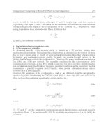
Operation of Active Front-End Rectifier in Electric Drive under Unbalanced Voltage Supply
209
by setting the magnitude of the voltage in phase A to 0.75 p.u. The corresponding maximal
input phase current magnitude, calculated as the maximum of all the phase currents, is
shown in Figure 29. It can be seen from Figure 28 that the resulting DC-link current
decreases in the vertical direction of the operating region, whereas the maximal input
current in Figure 29 decreases in the horizontal direction. The corresponding measure of the
current unbalance is depicted in Figure 30 and the average power factor of all the three
input phases is depicted in Figure 31.
Fig. 29. Maximal input phase current under unbalanced voltage supply (L = 10 mH,
R = 0.1 Ω, V
dc
= 400 V).
Fig. 30. Input current unbalance under unbalanced voltage supply (L = 10 mH, R = 0.1 Ω,
V
dc
= 400 V).
Fig. 31. Power factor under unbalanced voltage supply (L = 10 mH, R = 0.1 Ω, V
dc
= 400 V).
Electric Machines and Drives
210
If we change the value of the input inductance from 10 mH to 1 mH, the constraints caused
by the switching functions remain the same as can be seen from Figures 32 through 35.
However, both the DC-link current and the input current increased nearly ten times as the
input reactance represents the main limiting factor for the currents entering the rectifier. The
excessive values of the currents would, in a case of a real rectifier, impose additional
restrictions to the operating regions resulting from current stress of electronic components
in the bridge. This can also be considered in the shape of new borders of operating regions.
Fig. 32. DC-link current under unbalanced voltage supply (L = 1 mH, R = 0.1 Ω,
V
dc
= 400 V).
Fig. 33. Maximal input phase current under unbalanced voltage supply (L = 1 mH, R = 0.1 Ω,
V
dc
= 400 V).
Fig. 34. Input current unbalance under unbalanced voltage supply (L = 1 mH, R = 0.1 Ω,
V
dc
= 400 V).
Operation of Active Front-End Rectifier in Electric Drive under Unbalanced Voltage Supply
211
Fig. 35. Power factor under unbalanced voltage supply (L = 1 mH, R = 0.1 Ω, V
dc
= 400 V).
A different situation arises when the input resistance is increased ten times to 1 Ω. The
corresponding electrical quantities are shown in Figures 36 through 39. The increase in the
DC-link and input phase currents is not as dramatic as the resistance plays less significant
role in limiting the currents than the inductance. The values of the currents are similar to the
ones in the first case.
Fig. 36. DC-link current under unbalanced voltage supply (L = 1 mH, R = 1 Ω, V
dc
= 400 V).
Fig. 37. Maximal input phase current under unbalanced voltage supply (L = 1 mH, R = 1 Ω,
V
dc
= 400 V).
Electric Machines and Drives
212
Fig. 38. Input current unbalance under unbalanced voltage supply (L = 1 mH, R = 1 Ω,
V
dc
= 400 V).
Fig. 39. Power factor under unbalanced voltage supply (L = 1 mH, R = 1 Ω, V
dc
= 400 V).
A change in the DC-link voltage introduces, on the other hand, a noticeable change in the
shape of constraints caused by the limitation of the switching functions. Figures 40 through
43 show the situation for the decrease in the DC-link voltage from 400 V to 200 V and
Figures 45 through 47 show the situation for the increase to 600 V. In the latter case, a rise of
an isolated restricted area in the right hand side of the figure completely surrounded by
available control space can be noticed.
Fig. 40. DC-link current under unbalanced voltage supply (L = 10 mH, R = 0.1 Ω,
V
dc
= 200 V).
Operation of Active Front-End Rectifier in Electric Drive under Unbalanced Voltage Supply
213
Fig. 41. Maximal input phase current under unbalanced voltage supply (L = 10 mH,
R = 0.1 Ω, V
dc
= 200 V).
Fig. 42. Input current unbalance under unbalanced voltage supply (L = 10 mH, R = 0.1 Ω,
V
dc
= 200 V).
Fig. 43. Power factor under unbalanced voltage supply (L = 10 mH, R = 0.1 Ω,
V
dc
= 200 V).
Electric Machines and Drives
214
Fig. 44. DC-link current under unbalanced voltage supply (L = 10 mH, R = 0.1 Ω,
V
dc
= 600 V).
Fig. 45. Maximal input phase current under unbalanced voltage supply (L = 10 mH,
R = 0.1 Ω, V
dc
= 600 V).
Fig. 46. Input current unbalance under unbalanced voltage supply (L = 10 mH, R = 0.1 Ω,
V
dc
= 600 V).
Measurements on an experimental system identical to the simulated one have been carried
out in order to verify the investigated method. The scope traces in Figure 48 show the
measured current in phase A and the DC link current when the negative-sequence in the
supply voltage is not compensated for by the control method and the DC link current,
therefore, contains significant component pulsating with a frequency of 100 Hz, twice the
Operation of Active Front-End Rectifier in Electric Drive under Unbalanced Voltage Supply
215
fundamental network frequency. The case when unbalanced voltage system is compensated
by the investigated control method is illustrated in Figure 49. It can be seen that the
pulsating component of the DC link current has been effectively eliminated by the
investigated method.
Fig. 47. Power factor under unbalanced voltage supply (L = 10 mH, R = 0.1 Ω, V
dc
= 600 V).
Fig. 48. Phase A current and DC-link current under unbalanced voltage supply without
elimination of pulsating component.
Fig. 49. Phase A current and DC-link current under unbalanced voltage supply with
elimination of pulsating component.
Electric Machines and Drives
216
7. Conclusion
It has been shown in the article that it is possible to effectively compensate for the unbalanced
voltage source at the input of a solid-state converter so that constant power flow into the DC
bus is maintained. The results of simulations show that the choice of the operating point of
front end converter may significantly affect the impact of the rectifier on the supplying power
grid. It is possible to select the optimal operating point according to the chosen optimization
criteria, which can be e.g. maximal power factor or current unbalance.
8. Acknowledgment
This work was supported by the Grant Agency of the Czech Republic under research grant
No. 102/09/1273 and by the Institutional Research Plan AV0Z20570509.
9. References
Stankovic, A. V. & Lipo, T. A. (2001). A Novel Control Method for Input Output Harmonic
Elimination of the PWM Boost Type Rectifier Under Unbalanced Operating
Conditions, IEEE Trans. on Power Electronics, 16, pp. 603-611, ISSN: 0885-8993.
Stankovic, A. V. & Lipo, T. A. (2001). A Generalized Control Method for Input-Output
Harmonic Elimination of the PWM Boost Type Rectifier Under Simultaneous
Unbalanced Input Voltages and Input Impedances, Power Electronics Specialists
Conference, pp. 1309-1314, ISBN: 0-7803-7067-8, Vancouver, Canada, June 2001.
Lee, K.; Jahns, T. M.; Berkopec, W. E. & Lipo, T. A. (2006). Closed-form analysis of
adjustable-speed drive performance under input-voltage unbalance and sag
conditions, IEEE Trans. on Industry Applications, vol. 42, no. 3., pp. 733-741,
ISSN: 0093-9994.
Cross, A. M.; Evans, P. D. & Forsyth, A. J. (1999). DC Link Current in PWM Inverters with
Unbalanced and Non Linear Loads, IEE Proc Electr. Power Appl., vol. 146, no. 6,
pp. 620-626, ISSN: 1350-2352.
Song, H. & Nam, K. (1999). Dual Current Control Scheme for PWM Converter Under
Unbalanced Input Voltage Conditions, IEEE Trans. on Industrial Electronics, 46,
pp. 953-959, ISSN: 0278-0046.
Chomat, M. & Schreier, L. (2005). Control Method for DC-Link Voltage Ripple Cancellation
in Voltage Source Inverter under Unbalanced Three-Phase Voltage Supply, IEE
Proceedings on Electric Power Applications, vol. 152, no. 3, pp. 494 – 500,
ISSN: 1350-2352.
Chomat, M.; Schreier, L. & Bendl, J. (2007). Operation of Adjustable Speed Drives under
Non Standard Supply Conditions, IEEE Industry Applications Conference/42th
IAS Annual Meeting, pp. 262-267, ISBN: 978-1-4244-1259-4, New Orleans, USA,
September 2007.
Chomat, M.; Schreier, L. & Bendl, J. (2009). Influence of Circuit Parameters on Operating
Regions of PWM Rectifier Under Unbalanced Voltage Supply, IEEE International
Electric Machines and Drives Conference, pp. 357-362, ISBN: 978-1-4244-4251-5,
Miami, USA, May 2009.
Chomat, M.; Schreier, L. & Bendl, J. (2009). Operating Regions of PWM Rectifier under
Unbalanced Voltage Supply, International Conference on Industrial Technology,
pp. 510 – 515, ISBN: 978-1-4244-3506-7, Gippsland, Australia, February 2009.
11
Space Vector PWM-DTC Strategy for
Single-Phase Induction Motor Control
Ademir Nied
1
, José de Oliveira
1
, Rafael de Farias Campos
1
,
Seleme Isaac Seleme Jr.
2
and Luiz Carlos de Souza Marques
3
1
State University of Santa Catarina
2
Federal University of Minas Gerais
3
Federal University of Santa Maria
Brazil
1. Introduction
Single-phase induction motors are widely used in fractional and sub-fractional horsepower
applications, mostly in domestic and commercial applications such as fans, refrigerators, air
conditioners, etc., operating at constant speed or controlled by an on/off strategy which can
result in poor efficiency and low-power factor. In terms of construction, these types of motors
usually have a main and an auxiliary stator winding, are asymmetrical and are placed 90
degrees apart from each other. The rotor is usually the squirrel-cage type. The asymmetry
presented in the stator windings is due to the fact that these windings are designed to be
electrically different so the difference between the stator windings currents can produce a
starting torque (Krause et al., 1995). Since it has main and auxiliary stator windings, the single-
phase induction motor is also known as a two-phase asymmetric induction motor.
In recent years, with the growing concern about low-cost operation and the efficient use of
energy, the advance in motor drive control technology made it possible to apply these
motors to residential applications with more efficiency. Different inverter topologies have
been proposed to drive single-phase induction motors, providing ways to save energy. In
dos Santos et al. (2010) different ac drive systems are conceived for multiple single-phase
motor drives with a single dc-link voltage to guarantee installation cost reduction and some
individual motor controls. In Wekhande et al. (1999) and Jabbar et al. (2004), Campos et al.
(2007a) and Campos et al. (2007b), two topologies are considered. One is a Half-bridge
inverter and the other is a three-leg inverter. The cost difference between the two topologies
lays in the fact that the H-bridge inverter needs two large capacitors in the dc link rated for
dc link voltage. Also, there is a need of two large resistors connected in parallel with the
capacitors to balance the voltage of the capacitors.
Despite the fact that the three-leg inverter has more switches, the development of power
modules and the need for just one capacitor in the dc link have decreased the topology cost.
Along with the reduced cost, a more efficient use of the dc link voltage is achieved.
Besides the effort for developing more efficient driving topologies, many strategies to
control single-phase motors have been proposed. In Jacobina et al. (1999), rotor-flux control,
stator-flux control and direct torque control (DTC) (Takahashi and Noguchi, 1986) are
analyzed. The main drawback of the two first strategies is that they use an encoder to obtain
Electric Machines and Drives
218
the speed signal. Since there is no need for speed and position signals, a DTC scheme
appears to be a suitable solution. But it has some disadvantages such as current and torque
distortions, variable switching frequency and low-speed operation problems (Buja and
Kazmierkowski, 2004). In Neves et al. (2002), a DTC strategy is applied for a single-phase
motor and the performance is improved with the use of pulse width modulation.
Along with control strategies and driver topologies, many researchers have investigated
ways to optimize modulation techniques applied in single-phase induction motor drives. In
Jabbar et al. (2004), space-vector modulation (SVPWM) is used to reduce the torque ripple
and alleviate the harmonic content at the terminals of the single-phase induction motor
being driving by a three-leg inverter. In Chaumit and Kinnares (2009) the proposed SVPWM
method controls the two-phase voltage outputs of an unbalanced two-phase induction
motor drive by varying the modulation index and voltage factors.
In this chapter, the authors are interested in studying the DTC strategy combined with the
SVPWM applied to a three-leg inverter topology to drive a single-phase induction motor.
2. Single-phase induction motor model
A single-phase induction motor with main and auxiliary windings is designed to be
electrically different. In order to make the motor self-starting, a capacitor is connected in
series with the auxiliary winding.
When the windings of a single-phase induction motor are fed independently (i.e., using a
voltage source inverter) one can consider a single-phase induction motor an example of an
unsymmetrical two-phase induction motor.
In this section, the mathematical model of a single-phase induction motor will be derived.
As is commonly done, the derivation of the motor model is based on classical assumptions:
• The stator and rotor windings are in space quadrature;
• The rotor windings are symmetrical;
• The magnetic circuit is linear and the air-gap length is constant;
• A sinusoidal magnetic field distribution produced by the motor windings appears in
the air gap;
• The motor is a squirrel-cage type. Therefore the rotor voltages are zero.
Since the single-phase induction motor will be considered as acting as a two-phase system,
to derive the dynamic motor model of the two-phase system, a common reference frame (a-
b) will be used, as shown in Fig. 1.
Fig. 1. Common reference frame (a-b).
Space Vector PWM-DTC Strategy for Single-Phase Induction Motor Control
219
Since the stator windings are in space quadrature, there is no magnetic coupling between
them. The same consideration is applied to the rotor windings. According to Krause et al.
(1995), the relations between the fluxes and currents can be established as:
as asas asbs asar asbr as
bs bsas bsbs bsar bsbr bs
ar aras arbs arar arbr ar
br bras brbs brar brbr br
LLLLi
LLLL i
LLLLi
LLLLi
λ
λ
λ
λ
⎡
⎤⎡ ⎤⎡⎤
⎢
⎥⎢ ⎥⎢⎥
⎢
⎥⎢ ⎥⎢⎥
=
⎢
⎥⎢ ⎥⎢⎥
⎢
⎥⎢ ⎥⎢⎥
⎣
⎦⎣ ⎦⎣⎦
(1)
In Equation (1), L
asas(bsbs)
is the stator windings self-inductance; L
arar(brbr)
is the rotor windings
self-inductance; L
asbr(bras)
, L
arbs(bsar)
and L
asar(aras)
,
L
bsbr(brbs)
are the mutual inductance between the
stator and rotor windings. Since the stator windings are in space quadrature and
asymmetric, and the rotor windings are in space quadrature and symmetric, the following
relations can be written:
asas as
LL=
(2)
bsbs bs
LL
=
(3)
0
asbs bsas
LL
=
=
(4)
0
arbr brar
LL
=
= (5)
arar brbr r
LLL
=
=
(6)
The self-inductances of stator and rotor are composed of a leakage inductance and a
magnetizing inductance. That way, a new set of equations can be derived:
as las mas
LLL
=
+ (7)
bs lbs mbs
LLL
=
+ (8)
rlrmr
LLL=+ (9)
where (L
las
, L
lbs
) and (L
mas
, L
mbs
) indicate the stator leakage inductance and magnetizing
inductance, respectively, and L
lr
and L
mr
indicate the rotor leakage inductance and
magnetizing inductance, respectively. Since the rotor windings are assumed to be
symmetric, Equation (9) expresses the rotor windings.
As shown in Fig. 1, there is an angular displacement between the stator and rotor windings
establishing a magnetic coupling between them which results in a mutual inductance. The
equation for the mutual inductances may be expressed in matrix form
cos sin
sin cos
sra r sra r
sr
srb r srb r
LL
L
LL
θ
θ
θ
θ
−
⎡
⎤
=
⎢
⎥
⎣
⎦
(10)
where L
sra
and L
srb
are the amplitude of the mutual inductances.
Thus, the Equation (1) can be rewritten as
Electric Machines and Drives
220
0cossin
0sincos
cos sin 0
sin cos 0
as as sra r sra r as
bs bs srb r srb r bs
ar sra r srb r r ar
br sra r srb r r br
LLLi
LL L i
LL L i
LL Li
λθθ
λθθ
λθθ
λθθ
−
⎡
⎤⎡ ⎤⎡⎤
⎢
⎥⎢ ⎥⎢⎥
⎢
⎥⎢ ⎥⎢⎥
=
⎢
⎥⎢ ⎥⎢⎥
⎢
⎥⎢ ⎥⎢⎥
−
⎣
⎦⎣ ⎦⎣⎦
(11)
The voltage equations expressed in the common reference frame may be written as
0
0
as as as as
bs bs bs bs
vr i
d
vri
dt
λ
λ
⎡
⎤⎡ ⎤⎡⎤ ⎡ ⎤
=+
⎢
⎥⎢ ⎥⎢⎥ ⎢ ⎥
⎣
⎦⎣ ⎦⎣⎦ ⎣ ⎦
(12)
00
00
rar ar
rbr br
ri
d
ri
dt
λ
λ
⎡
⎤⎡ ⎤⎡⎤ ⎡ ⎤
=+
⎢
⎥⎢ ⎥⎢⎥ ⎢ ⎥
⎣
⎦⎣ ⎦⎣⎦ ⎣ ⎦
(13)
Inserting Equation (11) in Equations (12) and (13), the single-phase induction motor model
acting as a two-phase system can be mathematically expressed by
0cossin
0sincos
0
cos sin 0
0
sin cos 0
as as sra r sra r
as as
bs bs srb r srb r
bs bs
ar
sra r srb r r r
br
sra r srb r r r
ddd
rL L L
dt dt dt
vi
dd d
rL L L
vi
dt dt dt
dd d i
LLrL
dt dt dt
i
dd d
LL rL
dt dt dt
θθ
θθ
θθ
θθ
⎡⎤
+−
⎢⎥
⎢⎥
⎡⎤ ⎡⎤
⎢⎥
+
⎢⎥ ⎢
⎢⎥
⎢⎥ ⎢
=
⎢⎥
⎢⎥ ⎢
⎢⎥
+
⎢⎥ ⎢
⎢⎥
⎣⎦ ⎣
⎢⎥
⎢⎥
−+
⎣
⎦
⎥
⎥
⎥
⎥
⎦
(14)
The torque can be determined as
_
()
T
T
ar as
sr
e
br bs
rmech
ii
dL
T
ii
d
θ
⎡
⎤⎡⎤
=
⎢
⎥⎢⎥
⎣
⎦⎣⎦
(15)
Since θ
r
= pθ
r_mech
, where p is the number of pole pairs and θ
r
is the electrical angle, and
θ
r_mech
is the actual angular displacement of the rotor, the Equation (15) can be rewritten
()
.
T
T
ar as
sr
e
br bs
r
ii
dL
Tp
ii
d
θ
⎡
⎤⎡⎤
=
⎢
⎥⎢⎥
⎣
⎦⎣⎦
(16)
In expanded form, (16) becomes
[(sincos) (cossin)]
e as sra ar r br r bs srb ar r br r
TpiLi i iLi i
θ
θθθ
=− + + − (17)
According to Krause et al. (1995), in order to obtain the motor mathematical model with
constant parameters, it is necessary to transform all the variables to the stationary reference
frame (d-q) as shown in Fig. 2. That way θ
r
= 0.
A transformation matrix is necessary in order to establish the new reference frame. Thus
cos sin
;
sin cos
rr
rr
T
θθ
θθ
⎡
⎤
=
⎢
⎥
−
⎣
⎦
1
cos sin
sin cos
rr
rr
T
θ
θ
θ
θ
−
−
⎡
⎤
=
⎢
⎥
⎣
⎦
(18)
Space Vector PWM-DTC Strategy for Single-Phase Induction Motor Control
221
Fig. 2. Stationary reference frame (d-q).
Applying the transformation matrix to Equations (14) and (17), then
00
00
0
0
ds srd
ds
s
s
ds
ds
qs srq
s
s
qs
q
s
qs
s
srd r
dr
rsrq r rr
s
q
r
srq
r
rsrd rr r
dL dL
r
dt dt
i
v
dL dL
r
i
v
dt dt
dL dL
i
pL r pL
dt dt
i
dL
dL
pL pL r
dt dt
ωω
ωω
⎡⎤
+
⎢⎥
⎢⎥
⎡
⎤
⎡⎤
⎢⎥
⎢
⎥
⎢⎥
+
⎢⎥
⎢
⎥
⎢⎥
=
⎢⎥
⎢
⎥
⎢⎥
⎢⎥
⎢
⎥
⎢⎥
+
⎢⎥
⎢
⎥
⎢⎥
⎢⎥
⎣⎦
⎢
⎥
⎣
⎦
⎢⎥
−−+
⎢⎥
⎣⎦
(19)
[]
ss ss
esr
sdr srdds
q
r
T
p
Lii Lii=− (20)
where the superscript s denotes the stationary frame. The torque can also be expressed as
()
r
em r
d
p
TT J B
dt
ω
ω
−= +
(21)
This analytical approach represents the single-phase induction motor as an asymmetric two-
phase motor. The dq voltages, currents, and fluxes for stator and rotor are,
respectively:
s
ds
v ,
s
q
s
v ,
s
ds
i ,
s
q
s
i ,
s
dr
i ,
s
q
r
i ,
s
ds
λ
,
s
q
s
λ
,
s
dr
λ
,
s
q
r
λ
. The terms
ds
L ,
q
s
L ,
r
L ,
srd
L ,
sr
q
L denote
the stator and rotor self-inductance and their respective mutual inductance. The stator and
rotor resistance are denoted by
ds
r ,
q
s
r ,
r
r . The motor electromagnetic-torque and the load
torque are indicated by
e
T and
m
T , respectively. The moment of inertia, viscous friction
coefficient and the motor speed are, respectively:
J , B and
r
ω
.
One of the drawbacks of dealing with an asymmetric motor lies in the pulsating
electromagnetic torque that occurs due to the unbalance between the stator variables, as can
be seen in (19) and (20). To overcome this drawback and to create a symmetric model, a
transformation of the stator variables employing the mutual inductances was proposed by
Correa et al. (2004). The transformation matrix and its application can be written as
Electric Machines and Drives
222
10
0
S
n
⎡
⎤
=
⎢
⎥
⎣
⎦
(22)
1
1
ss
ds ds
ss
qs qs
vv
S
vv
⎡
⎤⎡⎤
⎢
⎥⎢⎥
=
⎢
⎥⎢⎥
⎣
⎦⎣⎦
(23)
1
1
1
ss
ds ds
ss
qs qs
ii
S
ii
−
⎡
⎤⎡⎤
⎢
⎥⎢⎥
=
⎢
⎥⎢⎥
⎣
⎦⎣⎦
(24)
1
1
1
ss
ds ds
ss
qs qs
S
λλ
λλ
−
⎡
⎤⎡⎤
⎢
⎥⎢⎥
=
⎢
⎥⎢⎥
⎣
⎦⎣⎦
(25)
The transformation element can be written as
srd
sr
q
L
n
L
=
.
When these transformations are applied to the mathematical model of the motor, the
unbalance between the main and auxiliary windings stator variables is eliminated. The new
symmetrical model of the single-phase induction motor acting as a two-phase system can be
given by the following equations:
111
111
0
.
0'
sss
ds
ds ds ds
sss
qs
qs qs qs
r
vi
d
r
dt
vi
λ
λ
⎡
⎤⎡⎤⎡⎤
⎡⎤
⎢
⎥⎢⎥⎢⎥
=+
⎢⎥
⎢
⎥⎢⎥⎢⎥
⎢⎥
⎣⎦
⎣
⎦⎣⎦⎣⎦
(26)
001
010
sss s
dr dr dr dr
r
r
sss s
r
q
r
q
r
q
r
q
r
vi
r
d
r
dt
vi
λ
λ
ω
λ
λ
⎡
⎤⎡⎤⎡⎤ ⎡⎤
⎡⎤ ⎡⎤
⎢
⎥⎢⎥⎢⎥ ⎢⎥
=++
⎢⎥ ⎢⎥
−
⎢
⎥⎢⎥⎢⎥ ⎢⎥
⎣⎦ ⎣⎦
⎣
⎦⎣⎦⎣⎦ ⎣⎦
(27)
11
11
0
0
0
0'
ss s
ds
ds ds dr
srd
ss s
srd
qs
q
s
q
s
q
r
L
ii
L
L
L
ii
λ
λ
⎡
⎤⎡⎤ ⎡⎤
⎡⎤
⎡⎤
⎢
⎥⎢⎥ ⎢⎥
=+
⎢⎥
⎢⎥
⎢
⎥⎢⎥ ⎢⎥
⎢⎥
⎣⎦
⎣⎦
⎣
⎦⎣⎦ ⎣⎦
(28)
1
1
00
00
ss s
dr dr ds
r srd
ss s
rsrd
qr qr qs
ii
LL
LL
ii
λ
λ
⎡
⎤⎡⎤ ⎡⎤
⎡⎤ ⎡ ⎤
⎢
⎥⎢⎥ ⎢⎥
=+
⎢⎥ ⎢ ⎥
⎢
⎥⎢⎥ ⎢⎥
⎣⎦ ⎣ ⎦
⎣
⎦⎣⎦ ⎣⎦
(29)
11
()
ss ss
esrd
q
sdr ds
q
r
TPLii ii=− (30)
where
2
'
q
s
q
s
LnL= and
2
'
q
s
q
s
rnr= .
According to Correa et al. (2004), if the asymmetry that appears in the motor model depends
only on the number of turns of each stator winding, then the ratio presented by
n will
corresponds approximately to refer the auxiliary winding variables to the main winding.
Also, if the inductances are slightly different, then '
q
sds
LL≈ .
Space Vector PWM-DTC Strategy for Single-Phase Induction Motor Control
223
Observing Equation (26) there is an asymmetry between the stator resistances. This term can
be isolated
111
111
0
.
0
sss
ds ds ds
ds
sss
ds
qs qs qs
vi
r
d
r
r
dt
vi
λ
λ
⎡⎤ ⎡⎤ ⎡⎤
⎡⎤
⎢⎥ ⎢⎥ ⎢⎥
=
++Δ
⎢⎥
⎢⎥ ⎢⎥ ⎢⎥
⎣⎦
⎣⎦ ⎣⎦ ⎣⎦
(31)
The term
rΔ is given by
2
1
0
()
s
q
sds
q
s
r
nr r i
⎡
⎤
Δ=
⎢
⎥
−
⎢
⎥
⎣
⎦
(32)
When dealing with motor control, it is necessary to write the dynamic equations of the
induction motor in an arbitrary reference frame. This transformation allows the
d-q variables
to be treated as dc signals, which is commonly used in control theory.
If
rΔ is considered negligible, a symmetric model of the single-phase induction motor in the
arbitrary reference frame can be derived as shown in Fig. 3.
Fig. 3. Revolving reference frame.
The transformation matrix is given by
cos sin
;
sin cos
aa
a
aa
T
θθ
θθ
−
⎡
⎤
=
⎢
⎥
⎣
⎦
1
cos sin
sin cos
aa
a
aa
T
θ
θ
θ
θ
−
⎡
⎤
=
⎢
⎥
−
⎣
⎦
(33)
When applying the transformation to the motor model based on the stationary reference
frame, given by (26) and (27), the resulting equations can be written in a different matrix
form:
111 1
111 1
001
010
aaa a
Ds Ds Ds Ds
s
a
aaa a
s
Qs Qs Qs Qs
vi
r
d
r
dt
vi
λλ
ω
λλ
⎡
⎤⎡⎤⎡⎤ ⎡⎤
−
⎡⎤ ⎡ ⎤
⎢
⎥⎢⎥⎢⎥ ⎢⎥
=++
⎢⎥ ⎢ ⎥
⎢
⎥⎢⎥⎢⎥ ⎢⎥
⎣⎦ ⎣ ⎦
⎣
⎦⎣⎦⎣⎦ ⎣⎦
(34)
00 01
.().
0100
aa a
Dr Dr Dr
r
ar
aa a
r
Qr Qr Qr
i
r
d
p
r
dt
i
λλ
ωω
λλ
⎡
⎤⎡⎤ ⎡⎤
−
⎡⎤
⎡⎤ ⎡⎤
⎢
⎥⎢⎥ ⎢⎥
=++−
⎢⎥
⎢⎥ ⎢⎥
⎢
⎥⎢⎥ ⎢⎥
⎣⎦ ⎣⎦⎣⎦
⎣
⎦⎣⎦ ⎣⎦
(35)
Electric Machines and Drives
224
11
11
00
00
aa a
Ds Ds Dr
ds srd
aa a
ds srd
Qs Qs Qr
ii
LL
LL
ii
λ
λ
⎡
⎤⎡⎤ ⎡⎤
⎡⎤ ⎡ ⎤
⎢
⎥⎢⎥ ⎢⎥
=+
⎢⎥ ⎢ ⎥
⎢
⎥⎢⎥ ⎢⎥
⎣⎦ ⎣ ⎦
⎣
⎦⎣⎦ ⎣⎦
(36)
1
1
00
00
aa a
Dr Dr Ds
rsrd
aa a
rsrd
Qr Qr Qs
ii
LL
LL
ii
λ
λ
⎡
⎤⎡⎤ ⎡⎤
⎡⎤ ⎡ ⎤
⎢
⎥⎢⎥ ⎢⎥
=+
⎢⎥ ⎢ ⎥
⎢
⎥⎢⎥ ⎢⎥
⎣⎦ ⎣ ⎦
⎣
⎦⎣⎦ ⎣⎦
(37)
The torque equation yields
11
[]
aa aa
e srd Qs Dr Ds Qr
TpLii ii=− (38)
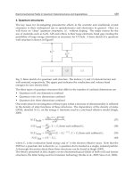
3. Conventional DTC scheme for single-phase induction motor
The basic DTC scheme consists of a logical switching table, which calculates the right
voltage vector to be applied by the inverter to obtain as fast a torque response as possible at
every instant. The control is based on error between the references and estimated values of
torque and flux magnitude and also uses the position of the estimated flux vector. The
torque and flux magnitude error signals are the inputs to the torque and flux hysteresis
controllers, respectively. That way, both the stator flux magnitude and the developed torque
can be directly controlled by proper selection of stator voltage space vectors in order to
reduce the torque and flux errors within the prefixed limits. The hysteresis determines the
inverter switching frequency, which varies with the synchronous speed and load conditions.
This technique achieves robust and fast torque response. Fig 4 shows the block diagram for
the conventional DTC scheme applied to a single-phase induction motor.
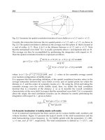
To determine the proper voltage vectors to be applied, a logical switching table must be made.
This can be achieved by dividing the dq plane into six sectors. A power inverter will be
employed in a three-leg configuration. That way the dq plane has the form of an asymmetric
hexagon, as shown in Fig 5. There are six active vectors and two zero vectors (V
7
and Vo). The
zero vectors are used to reduce the torque. Since a single-phase induction motor can be viewed
as a two-phase induction motor, there is no need for three-to-two phase transformation for the
primary voltage and current. Another aspect concerning this method of control is the absence
of field orientation which makes the control task a less complex issue.
So for the conventional DTC, the following equations are derived from (26) to estimate the
stator flux
()
sss
sd sd sd sd
vridt
λ
=−
∫
(39)
()
sss
sq sq sq sq
vridt
λ
=−
∫
(40)
The electromagnetic torque as a function of stator variables can be written as:
()
ss ss
es
q
sd sd s
q
Tpi i
λ
λ
=− (41)
Estimation of the stator flux by pure integration can present instability, especially at low
speeds. This problem can be overcome by using a low-pass filter instead of a pure integrator
or other filtering techniques presented in Hu (1998).
Space Vector PWM-DTC Strategy for Single-Phase Induction Motor Control
225
Fig. 4. Block diagram of the basic DTC scheme.
Fig. 5. Space-vectors hexagon.
Since DTC uses hysteresis control resulting in a so-called bang-bang control of the torque
and flux, the result is a fast response of the control commands. However, the steady state
performance is characterized by undesirable ripples in current, flux and torque. To avoid
such effects, a high switching frequency should be delivered by the hysteresis loops. But the
amplitude of the hysteresis band has a strong effect on those undesirable ripples mentioned
above (Noguchi and Takahashi, 1997). To eliminate these issues, instead of using a
switching table, a pulse width modulator can be used. Basically, the DTC scheme can be
implemented by means of a closed-loop PI controller which will calculate the required stator
Electric Machines and Drives
226
voltage vector and then will be synthesized by a PWM technique (Jabbar et al., 2004).
Therefore, the pulse width modulator is used to optimize the steady state drive
performance.
4. Space vector modulation technique
To control the three-leg inverter driving a single-phase induction motor indirectly, space
vector PWM can be employed. This approach is known to deliver less harmonic distortion in
the output voltages applied to the phases of the induction motor. Consequently, the ripples in
the stator current are diminished and a smooth flux and torque waveform is obtained.
In Correa et al. (2002), Tomaselli et al. (2004) and Jabbar et al. (2004), a space vector
modulation applied to a three-leg inverter driving a single-phase motor is presented. As
shown in Fig. 6, the spatial disposition of the space vectors differs from the one found when
the same inverter system drives a three-phase induction motor. In the latter, the space vector
displays a symmetric hexagon (Zhou, 2002). For the single-phase system, the space vectors
form an asymmetric hexagon (Jabbar et al., 2004). Since the voltages supplied by the three-
leg inverter to the motor phases are sinusoidal waves 90
0
degrees apart from each other, the
stator voltage vector can be decomposed into real and imaginary parts,
** *ss
ds
q
s
vv
j
v=+ (42)
The reference vector
*
v is used to determine the switching signals that will drive the three-
leg inverter. The adjacent vectors
*s
ds
v and
*s
q
s
v display the magnitude of the resulting
switching vectors. Similar to the three-phase inverter feeding a three-phase induction motor,
in a three-phase inverter feeding a two-phase induction motor there are eight voltage
vectors to be applied (six active vectors and two zero vectors). Table I presents the eight
voltage vectors that can be applied to the motor (
V
n
indicates the resulting space vectors
with
n = 0,1,2,…,7).
From the asymmetric hexagon, one can see that there are four vectors with amplitude E
(
V
1
,V
3
,V
4
,V
6
), two vectors with amplitude
2
E (V
2
,V
5
) and two null vectors (V
0
,V
7
).
Fig. 6. Space Vectors spatial disposition.
Space Vector PWM-DTC Strategy for Single-Phase Induction Motor Control
227
n
V
S
1
S
2
S
3
s
ds
v
s
q
s
v
0
V
0 0 0 0 0
1
V
1 0 0 E 0
2
V
1 1 0 E E
3
V
0 1 0 0 E
4
V
0 1 1 -E 0
5
V
0 0 1 -E -E
6
V
1 0 1 0 -E
7
V
1 1 1 0 0
Table 1. Switching states and the adjacent vectors amplitude.
According to Jabbar et al. (2004), the reference vector and the adjacent vectors can be related
by the following equation:
***ss
p
wm ds ds
q
s
q
s
TV tV tV=⋅ +⋅ (43)
In Equation (19),
ds
t
and
q
s
t are the durations in time in which the vectors
*s
ds
V and
*s
q
s
V are
within period
p
wm
T . The period of duration of the zero vectors can be defined by
0
p
wm ds
q
s
tT t t
=
−− (44)
5. SVPWM-DTC Proposed Scheme
As mentioned in Section 3, to optimize the steady state performance and to diminish the
switching harmonics, a pulse width modulator can be applied. An improvement can be
achieved when torque and stator flux magnitude are controlled by PI controllers using a
closed-loop. The DTC strategy adapted to single-phase induction motors was discussed in
Jacobina et al. (1999) and Neves et al. (2002). Fig. 7 shows the proposed scheme. The essence of
DTC is kept, since its principle of accelerating the flux vector to increase torque is maintained,
and there is no need for speed or position signals. The output signals of the PI controllers can
be viewed as stator voltage components operating in Cartesian coordinates. After the reference
frame transformation, the PWM is fed with the stator voltage components in the stationary
frame. The control strategy relies on the stator flux orientation; therefore, the arbitrary
reference frame should be aligned with the stator flux vector,
as
f
θ
θ
=
.
The condition to achieve the field orientation can be expressed by
1
;
sf
s
Ds
λ
λ
=
1
0
sf
Qs
λ
=
(45)
To determine the dynamic equations for the proposed technique, some algebraic
manipulations must be done. Taking the Equations (34), (35), (37), aligned with the stator
reference frame, the designed control signals can be derived:
111
sf sf sf
sssrdrrsd
ssrd
Ds Ds Ds
ds s ds s r srd srd
dLLLL
viLi
dt L L L
λλ
λ
τσ τσ
⎡
⎤
=+− − +
⎢
⎥
⎣
⎦
(46)
Electric Machines and Drives
228
1
11
s
f
s
f
Qs Qr
sf sf
srd
qs qs s
Qs Qs
r
di d
L
vriL
dt L dt
λ
σ
=+ +
(47)
where,
2
1/()
ssrdrsd
LLL
σ
=− (48)
Fig. 7. SVPWM-DTC proposed scheme.
By manipulating (46) and (47) in the synchronous frame, the designed control signals can be
obtained as:
1
sf
ss
ds
Ds
ds s
d
ve
dt
λλ
τσ
=++ (49)
1
11
sf
Qs
sf sf
q
s
q
ss
q
s
Qs Qs
di
vriL e
dt
σ
=+ + (50)
assuming the terms
e
ds
and e
qs
as feed-forward elements and given by (51) and (52), and
considering the terms that indicate the asymmetry and disturbance negligible:
11
sf sf
srd r r ds
ds s srd
sD sD
ds s r srd srd
LLLL
eiLi
LL L
λ
τσ
⎡
⎤
=− − +
⎢
⎥
⎣
⎦
(51)
1
sf
srd r sd
qs
sQ
r srd
LrL
ei
LL
⎡
⎤
=
⎢
⎥
⎣
⎦
(52)
The torque as function of stator flux and currents is given by: