Advances in Gas Turbine Technology Part 14 pdf
Bạn đang xem bản rút gọn của tài liệu. Xem và tải ngay bản đầy đủ của tài liệu tại đây (8.38 MB, 30 trang )
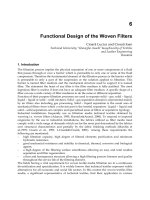
Advances in Gas Turbine Technology
380
ε
= A
n
exp(-Q/RT)
Here,
A and n are dimensionless coefficients, is the creep stress, Q is the activation energy
for the creep,
T is the absolute temperature, while R is the gas constant.
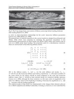
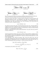
In Fig. 9,the value of n is around 1-2 for sintered composites, and 5-6 for Al
2
O
3
/YAG single
crystal composites. In sintered composites, it can be assumed that the creep deformation
mechanism follows the Nabarro-Herring or Coble creep models,while in Al
2
O
3
/YAG single
crystal composites,the creep deformation mechanism can be assumed to follow the
dislocation creep models corresponding to the dislocation structure in Fig. 10. The activation
energy
Q is estimated to be about 700 kJ/mol from an Arrhenius plot, which is not so
different from the values estimated from the high temperature creep in Al
2
O
3
single crystal
(compression axis is [110]) and YAG single crystal (compression axis is [110] ). It is also
reported that the activation energy for oxygen diffusion in Al
2
O
3
is about 665 kJ/mol, which
is not so far from the activation energy of Al
2
O
3
single crystal for plastic flow even though
that of A
+
diffusion is about 476 kJ/mol. This fact means that the deformation mechanism of
the Al
2
O
3
single crystal is the diffusion controlled dislocation creep. On the other hand,the
activation energy for oxygen diffusion in YAG is about 310 kJ/mol, which differs
significantly from the activation energy of YAG single crystal for plastic now.
However,dislocation is always observed in both Al
2
O
3
phase and YAG phase of
compressively deformed specimens at 1773 K-1973 K and at strain rate of 10
-4
/s – 10
-6
/s.
Therefore,the compressive deformation mechanism of the Al
2
O
3
/YAG single crystal
composite must follow the dislocation creep models (Wake & Sakuma, 2000; Waku et al.,
2002).
Fig. 9. Relationship between compressive flow stress and strain rate for an Al
2
O
3
/YAG
single crystal composite, a sintered composite and an a-axis sapphire.
Unidirectionally Solidified Eutectic
Ceramic Composites for Ultra-High Efficiency Gas Turbine Systems
381
Fig. 10. TEM images showing the dislocation structure of (a) Al
2
O
3
phases and (b) YAG
phases in the Al
2
O
3
/YAG single crystal composite, and (c) the microstructure of Al
2
O
3
and
YAG phases in the sintered composite, of compressively crept specimens at 1873 K and
strain rate of 10
-5
/s.
5.4 Tensile creep rupture
To date a lot of isolated studies have been done on the creep behavior of various highly
resistant structural materials. A direct comparison of creep results from different sources is
not simple because they have usually been obtained under different test conditions; for
instance, with different combinations of temperature and stress. To make a meaningful
comparison of creep resistance, the creep data was evaluated here using a Larson-Miller
parameter. Figure 3 shows the relationship between tensile creep rupture strength and
Larson-Miller parameter, T(22+log t) (DiCarlo & Ynn 1999), for Al
2
O
3
/YAG binary MGC
compared with that of polymer-derived stoichiometric SiC fibers: Hi-Nicalon Type S (Yun &
DiCarlo, 1999), Tyranno SA (1, 2) (Yun & DiCarlo, 1999), and Sylramic (1) (Yun & DiCarlo,
1999) , those of silicon nitrides (Krause, 1999), an Al
2
O
3
/SiC nanocomposite (Ohji, 1994).
Here T is the absolute temperature; t is the rupture time in hours. For comparison, the
Larson-Miller curve for a representative superalloy, CMSX
®
-10 (Erickson, 1996), is shown in
Fig. 11 as well.
The relationship between tensile creep rupture strength and Larson-Miller parameter shows
three broad regions. The Larson-Miller parameter for CMSX
®
-10 is 32 or less in region I.
This material is already being used for turbine blades in advanced gas turbine systems at
above 80% of its melting temperature, and its maximum operating temperature is
approximately 1273- 1373 K. It is not envisioned that the heat resistance of this superalloy
will be significantly improved in the future. On the other hand, advanced ceramics such as
silicon nitrides, SiC fibers, and a nanocomposite are found in region II where the Larson-
Miller parameter is between 33 and 42. These materials are promising candidates for high
temperature structural materials. They have better high temperature resistance than the
superalloys. The creep strength of SiC fibers is approximately coincident with that of silicon
nitrides and significantly higher than that of the Al
2
O
3
/SiC nanocomposite.
In contrast, the Al
2
O
3
/YAG binary MGC is found in region III where the Larson-Miller
parameter is between 44 and 48. The high temperature resistance of this MGC is superior to
that of the silicon nitrides, the SiC fibers and the Al
2
O
3
/SiC nanocomposite. The creep
Advances in Gas Turbine Technology
382
deformation mechanisms for the MGC are believed to be essentially different from the grain
boundary sliding or rotation of the sintered ceramics. We conclude that the network
microstructure of MGC can be regarded as a suitable microstructure for super high
temperature material (Waku et al., 2004).
Fig. 11. Larson-Miller creep rupture strength of MGC compared to other heat-resistant
materials.
5.5 Oxidation resistance and thermal stability
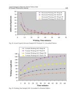
Fig. 12 shows the change in mass of eutectic composites manufactured by the unidirectional
solidification method when these eutectic composites are exposed for a fixed period in an air
atmosphere at 1973 K. For a comparison, Fig. 12 also shows the results of oxidation
resistance tests performed under the same conditions on ceramics SiC and Si
3
N
4
. As the Fig.
12 shows, Si
3
N
4
was shown to be unstable. When it was exposed to 1973 K for 10 hours in
the atmosphere, the following reaction took place; Si
3
N
4
+3O
2
→3SiO
2
+2N
2
and the collapse
of the shape of the Si
3
N
4
occurred. Likewise, when SiC was held at 1973 K for 50 hours, it
was also shown to be unstable. The following reaction took place; 2SiC+3O
2
→2SiO
2
+2CO
and the collapse of the shape also occurred (Waku et al., 1998).
On the other hand, when the unidirectionally solidified Al
2
O
3
/YAG eutectic composite was
exposed in an air atmosphere at 1973 K for 1000 hours, the composite displayed excellent
oxidation resistance with no change in mass whatsoever (Waku et al., 1998).
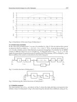
Fig. 13 shows the relationship between flexural strength and heat treatment time at 1973 K
in an air atmosphere. For comparison, Fig. 13 also shows results for SiC and Si
3
N
4
. When the
unidirectionally solidified eutectic composite was tested following exposure, there were no
Unidirectionally Solidified Eutectic
Ceramic Composites for Ultra-High Efficiency Gas Turbine Systems
383
changes in flexural strengths both at room temperature and 1973 K, demonstrating that the
composite is an extremely stable material. In contrast, when SiC and Si
3
N
4
were heated to
1973 K in an air atmosphere for only 15 minutes, a marked drop in flexural strength
occurred. Figure 9 shows changes in the surface microstructure of these test specimens
before and after heat treatment. There was little difference in surface microstructure of the
unidirectionally solidified eutectic composite following 1000 hours of oxidation resistance
testing (Waku et al., 1998).
Fig. 12. Comparison of oxidation resistance characteristics of a unidirectionally solidified
eutectic composites and advanced ceramics SiC and Si
3
N
4
at 1973 K in an air atmosphere.
Al
2
O
3
/YAG and Al
2
O
3
/EAG binary MGCs have excellent oxidation resistance with no
change in mass gain for 1000 hours at 1973 K in an air atmosphere(Waku et al., 1998). There
were also no changes in flexural strength both at room temperature and 1973 K even after
heat treatment for 1000 hours at 1973 K in an air atmosphere. In contrast, when advanced
ceramic Si
3
N
4
was exposed to 1973 K for 10 hours in the atmosphere, the collapse of the
shape occurred. Likewise, when SiC was held at 1973 K for 50 hours, it was also shown to
be unstable owing to the collapse of the shape also occurred.
Fig. 14 shows SEM images of the microstructure of an Al
2
O
3
/EAG binary MGC after 500
750, 1000 hours of the heat treatment at 1973 K in an air atmosphere. Even after 1000 hours
of heat treatment no grain growth of microstructure was observed. The MGCs were shown
to be very stable during lengthy exposure at high temperature of 1973 K in an air
atmosphere. This stability resulted from the thermodynamic stability at that temperature of
the constituent phases of the single-crystal like Al
2
O
3
and the single-crystal EAG, and the
thermodynamic stability of the interface. In contrast, a sintered composite shows grain
1000
8006004002000
-1.0
-0.8
-0.6
-0.4
-0.2
0.0
0.2
0.4
0.6
0.8
1.0
Mass Gain / mass %
Si3N4, Collapse of Shape
SiC, Collapse of Shape
Unidirectionally Solidified
Eutectic Composite
Time of heat treatment / h
Advances in Gas Turbine Technology
384
growth and there are many pores lead to reduction of strength at 1973 K only for 100hr
(Nakagawa et al., 1997; Waku et al., 1998).
Time of heat treatment / h
0.5
0.6
0.7
0.8
0.9
1.0
1.1
1.2
R.T.
1973 K
Unidirectionally Solidified
Eutectic Composite
SiC, R.T.
Si3N4, R.T.
0 500 1000
Relative Strength
Fig. 13. Changes caused by length of heating in relative strength of unidirectionally
solidified eutectic composites and advanced ceramics SiC and Si
3
N
4
at room temperature at
1973 K. The relative strength is the ratio of flexural strength after a
prescribed period of
heating in an air atmosphere at 1973 K to as-received flexural strength.
6. MGC gas turbine systems
Feasibility studies were performed for a leading research project during 1988-2000 in Japan.
Based on the results, work was conducted under a NEDO national project from 2001 to 2005.
The objective of this project is the development of a 1973 K class uncooled, TBC/EBC-free
gas turbine system using MGCs. A paper engine was designed to study component
requirements and to estimate its performance. The size of the gas turbine chosen was a
relatively small 5MW class. By increasing TIT from the conventional 1373 K to 1973 K,
without cooling the nozzle vane and raising the engine pressure ratio from 15 to 30, the
thermal efficiency of the gas turbine increased from 29% to 38%. Fig. 15 shows the estimated
improvement compared with a current gas turbine. Both are simple cycle gas turbines, and
the efficiency is defined at the electrical output (Kobayashi, K., 2002). The final targets of the
national project for the MGC gas turbine system are: output power: 5MW class, overall
Unidirectionally Solidified Eutectic
Ceramic Composites for Ultra-High Efficiency Gas Turbine Systems
385
pressure ratio: 30, turbine inlet temperature (TIT): 1973 K, and a non-cooled MGC turbine
nozzle. The relationship between the thermal efficiency and the specific power depends
strongly on the turbine inlet temperature and the overall pressure ratio. The current
efficiency of a 5MW-class gas turbine is around 29%. In contrast, the efficiency of the MGC
gas turbine with the uncooled turbine nozzle is higher than that of the conventional gas
turbine. For a TIT of 1973 K and a pressure ratio of 30, the 29% efficiency of the conventional
5 MW-class gas turbine increases to 38%.
Fig. 14. SEM images showing thermal stability of the microstructures at 1973 K in an air
atmosphere in Al
2
O
3
/EAG binary MGCs: (a) as-received, after heat treatment for (b) 500 h,
(c) 750 h, (d) 1000 h and Al
2
O
3
/EAG sintered composites: (e) as-received and after heat
treatment for (f) 100 h.
Advances in Gas Turbine Technology
386
Fig. 15. Gas turbine performance curve as a function of specific power.
MGCs have outstanding high temperature characteristics up to a very high temperature, but
the MGC has low thermal shock resistance. First, a hollow nozzle vane was tested at the
maximum temperature of 1673 K which is the maximum allowable temperature for the
current nozzle rig. The estimated maximum steady state stress using the measured
temperature distribution was 211 MPa. To decrease the steady state stress more, a bowed
stacking nozzle design is being developed.
An Al
2
O
3
/GAP binary MGC with high temperature strength superior to that of an
Al
2
O
3
/YAG binary is being examined as a candidate material for the bowed stacking nozzle.
Fig. 16 shows the external appearance of the bowed stacking nozzle machined from an
Al
2
O
3
/GAP binary MGC ingot, 53 mm in diameter and 700 mm in length. The steady state
temperature and thermal stress distribution at a TIT of 1973 K (see Fig 17) have been
analyzed. The maximum temperature is around 1973 K, and it is observed along the central
vane section from leading edge to trailing edge at the surface of the bowed stacking nozzle.
The maximum steady state thermal stress, generated at the trailing edge of the nozzle, is
estimated at 117 MPa. On the other hand, the maximum transient tensile stress in the
bowed stacking nozzle during shut-down in one second from 1973 K to 973 K, generated at
the leading edge near the mid-span location at 1373 K-1473 K, is estimated at 482 MPa (see
Fig. 18). This value is smaller than the estimated ultimate flexural strength of 770 MPa at
1773K of the Al
2
O
3
/GAP binary MGC (Waku et al., 2003). A rig test at a gas inlet
temperature of 1973 K is planned in order to ensure the structural integrity under steady
state and thermal shock conditions. The bowed stacking nozzle in Fig. 16 was manufactured
from an Al
2
O
3
/GAP binary MGC ingot by machining with a diamond wheel. Existing rig
equipment is being improved for the 1973 K test to enable measurement of a continuous
temperature distribution on the nozzle surface by using an infrared camera. It is feasible to
verify the structural integrity of the MGC bowed stacking turbine nozzle using this
equipment under these hot gas conditions.
Unidirectionally Solidified Eutectic
Ceramic Composites for Ultra-High Efficiency Gas Turbine Systems
387
Fig. 16. A bowed stacking nozzle manufactured from an Al
2
O
3
/GAP binary MGC ingot by
machining using a diamond wheel.
Fig. 17. Steady thermal stress generated during hot gas flow at 1700
C estimated by using
numerical analysis.
Advances in Gas Turbine Technology
388
Fig. 18. Transient thermal stress under TRIP condition from 1973 K estimated by using
numerical analysis.
7. MGC gas turbine component
Fig.19 shows the SEM images of microstructure of cross-section perpendicular to the
solidification direction of the Al
2
O
3
/YAG and Al
2
O
3
/GAP binary MGCs after 0 - 1000 hours
of heat treatment at 1700 ºC in an air atmosphere. In case of Al
2
O
3
/YAG binary MGC (Fig.19
(a) and (b)) even after 1000 hours of heat treatment, no grain growth of microstructure was
observed. While in case of Al
2
O
3
/GAP binary MGC (Fig. 19 6 (c) and (d)), a slight grain
growth was observed. However, both MGCs were shown to be comparatively stable
without void formation during lengthy exposure at high temperature of 1973 K in an air
atmosphere. This stability resulted from the thermodynamic stability at that temperature of
the constituent phases of the single-crystal Al
2
O
3,
the single-crystal YAG and the single-
crystal GAP, and the thermodynamic stability of the interface.
Fig. 20 shows a relationship between flexural strength at room temperature and the time of
heat treatment at 1973 K in an air atmosphere. The Al
2
O
3
/YAG binary MGC has about 300 –
370 MPa of the flexural strengths after the heat treatment for 1000 hours at 1973 K in an air
atmosphere. This strength is the same value as the as-received. While, the flexural strength
of the Al
2
O
3
/GAP binary MGC after heat treatment for 1000 hours at 1973 K in an air
atmosphere has about 500 MPa slightly lower than that of the as-received. In the case of the
Al
2
O
3
/GAP binary MGC, although the a little drop in the flexural strength in seen a shot
time later of the heat treatment, the flexural strength after 200 hours of the heat treatment is
independent of the heat treatment time. Both MGCs exhibited good thermal stability at very
high temperature of 1973 K in an air atmosphere.
Unidirectionally Solidified Eutectic
Ceramic Composites for Ultra-High Efficiency Gas Turbine Systems
389
Fig. 19. SEM images showing microstructural changes of cross-section perpendicular to the
solidification direction of binary MGCs before and after heat treatment until 1000 hours at
1973 K in an air atmosphere. (a) and (b): the Al
2
O
3
/YAG binary MGC. (c) and (d): the
Al
2
O
3
/GAP binary MGC. (a) and (c) are for 0 hour. (b) and (d) are for 1000 hours.
Fig. 20. Relationship between flexural strength at room temperature and time of heat
treatment at 1973 K in an air atmosphere.
30 μm
30 μm
(d)
0 h
(c)
1000 h
60 μm
(a)
0 h
60 μm
(b)
1000 h
Al
2
O
3
/GAP binar
y
MGC
Al
2
O
3
/YAG binar
y
MGC
Advances in Gas Turbine Technology
390
8. New Bridgman type furnace
MGCs are fabricated by unidirectional solidification from molten oxide eutectic
compositions. The melting experiments are conducted at very high temperatures, hence a
new Bridgman-type furnace, designed to accurately control many process parameters at
super high temperatures, was acquired. Fig.21 is the schematic drawing of the new
Bridgman-type furnace. The equipment consists of a casting chamber, a vacuum chamber
and a driving device. The schematic on the right of Fig. 21 shows the casting chamber. The
casting chamber consists of a heating and melting zone and a cooling zone. Both zones can
independently control their temperatures by high frequency induction heating. The
Bridgman type furnace has the following features: (1) measurement and control of high
temperature around 2300 K, (2) precise control of temperature gradients at near the liquid-
solid interface by controlling the melting zone and the cooling zone independently, and (3)
the ability to fabricate large MGC components with a maximum size of 300 mm in diameter
and 500 mm in length.
Fig.22 shows the external appearance of the new Bridgman-type furnace at JUTEM (Japan
Ultra-High Temperature Materials Research Center). The equipment consists of a controller
panel, a cooling water system, a casting chamber and a vacuum pump system. The upper
right figure is the main controller panel. The lower right figure shows the inside of the
casting chamber. The casting chamber consists of a heating and melting zone and a cooling
zone. The heating and melting zone is used to heat a Mo crucible and then melt an oxide
eutectic raw material in the Mo crucible. The cooling zone is used to control the temperature
gradient close to an interface between solid and liquid. Both zones can independently
control their temperatures by high frequency induction heating. The lower left figure shows
the cooling water equipment.
Fig. 21. Schematic drawing of new Bridgman-type furnace
Unidirectionally Solidified Eutectic
Ceramic Composites for Ultra-High Efficiency Gas Turbine Systems
391
Fig. 22. New Bridgman-type furnace
9. Molybdenum crucible for near-net shape casting
9.1 Plasma sprayed molybdenum mold
Molybdenum is the most suitable material for fabricating MGC parts. Fabrication of a near-
net-shaped crucible was attempted by plasma spraying of molybdenum powder on a copper
model with a complex shape. The mold was obtained by plasma spraying the molybdenum
powders on the copper model. Fig.23 shows plasma spraying of the molybdenum crucible
for near-net-shape casting. The plasma spraying was performed using Mo powder with a
particle diameter of 20~40 µm in a vacuum atmosphere (about 100 mmHg). The copper
model was completely removed from the plasma sprayed mold by melting at 1473 K. Fig.24
shows the external appearance of the plasma sprayed molybdenum mold and its cross
section at the middle of the longitudinal direction. The microstructure of the plasma sprayed
Mo mold is relatively homogeneous, though it does include some pores. The thickness of
wall of the mold is 2-3 mm.
Fig.25 shows the roughness of the internal surface of the plasma sprayed molybdenum
mold, with or without shot peening to the Cu model, together with the relatively smooth
surface of an extruded molybdenum mold for comparison. Shot peening causes the internal
surface of the Cu model to be very rough. It is difficult to remove the MGC from the
molybdenum mold after unidirectional solidification. Hence, it is necessary to improve the
surface roughness of the mold. To achieve this, the molybdenum powder was
plasmasprayed without shot peening to the Cu model. To improve the adhesion of the
molybdenum powder, the temperature of the copper model was raised by about 150 K
Advances in Gas Turbine Technology
392
compared to the plasma spraying with shot peening. The surface roughness of the internal
wall of the plasma sprayed mold without shot peening to the Cu model was found to be
significantly improved compared with that of the plasma sprayed mold with shot peening.
The surface roughness of the plasma sprayed molybdenum mold without shot peening to
the Cu model appears to be comparable to that of the extruded molybdenum mold.
Fig. 23. A plasma spraying scene to produce the quasi-turbine nozzle mold for near-net
shaped casting.
Fig. 24. Plasma sprayed crucibles. (a) External appearance of the crucible manufactured by
plasma spraying of molybdenum powder on the copper master mold and (b) its cross-
sectional diagram.
(a)
(b)
Unidirectionally Solidified Eutectic
Ceramic Composites for Ultra-High Efficiency Gas Turbine Systems
393
Fig. 25. Cross-sectional microstructure showing roughness on the internal surface of plasma
sprayed crucible by Mo powder (a) with shot peening, (b) without shot peening, and (c) Mo
crucible produced by extrusion.
9.2 Unidirectional solidification
Fig. 26 shows SEM images of the microstructure of a cross-section perpendicular to the
solidification direction of an Al
2
O
3
/YAG and an Al
2
O
3
/GAP binary MGC fabricated using
the plasma sprayed molybdenum mold and the new Bridgman type furnace. For the
Al
2
O
3
/YAG binary MGC (Fig. 26 (a)), the light area is the YAG phase with a garnet
structure, and the dark area is Al
2
O
3
phase with a hexagonal structure in the same way as
The dimensions of the microstructures are 15-20 µm, smaller than that of the Al
2
O
3
/YAG
binary MGC produced using the extruded mold. Homogeneous microstructures with no
pores or colonies are observed in the Al
2
O
3
/YAG binary MGC fabricated using the plasma
Advances in Gas Turbine Technology
394
sprayed Mo mold. However, the microstructure near the mold is bigger than that for the
center.
For the Al
2
O
3
/GAP binary MGC (Fig. 26 (b)), the light area in the SEM micrograph is the
GAP phase, and the dark area is the Al
2
O
3
phase in the same way as Fig. 3(b). The
dimensions of the microstructures are 2-4 µm, a little smaller than those of the Al
2
O
3
/GAP
binary MGC produced using the extruded Mo crucible. Homogeneous microstructures with
no pores or colonies are observed in the Al
2
O
3
/GAP binary MGC fabricated using the
plasma sprayed Mo mold.
Fig. 26. SEM images of the microstructure of a cross-section perpendicular to the
solidification direction of an Al
2
O
3
/YAG (a) and an Al
2
O
3
/GAP (b) binary MGC using
manufactured using the plasma sprayed Mo mold.
(a)
(b)
25 μm
25 μm
Unidirectionally Solidified Eutectic
Ceramic Composites for Ultra-High Efficiency Gas Turbine Systems
395
9.3 High temperature strength
Fig. 27 shows the temperature dependence of the flexural strength from room temperature
to 1973 K of Al
2
O
3
/YAG binary MGCs, which was produced by using the plasma, sprayed
Mo mold and the extruded Mo crucible. Both MGCs maintain their temperature strength up
to 1973 K, with a flexural strength in the range of 260~350 MPa. Namely, the temperature
dependence of strength of the Al
2
O
3
/YAG binary MGC produced using the plasma sprayed
Mo mold is almost the same as that of the Al
2
O
3
/YAG binary MGC produced using the
extruded Mo crucible.
Fig. 27. Temperature dependence of the flexural strength from room temperature to 1973 K
of different Al
2
O
3
/YAG binary MGCs fabricated using the plasma sprayed Mo mold and
using the extruded Mo crucible.
10. Conclusions
MGCs have the unique microstructure of a three-dimensionally continuous network of
single crystal phases without grain boundaries. Therefore, MGCs have many advantages
such as excellent high temperature strength, creep resistance, superior thermal stability as
ultra-high temperature structural materials. The NEDO project for a gas turbine system
using MGCs has been briefly introduced along with current research topics for system
integration and innovative process and manufacturing technology. The manufacturing
process of a plasma sprayed molybdenum mold for near-net-shaped casting of the gas
turbine component was also introduced. We have recently been successfully fabricated the
0
100
200
300
400
500
600
700
800
0 500 1000 1500 2000 2500
◆
fabricated using the extruded
Mo crucible
■
fabricated using the plasma
s
p
ra
y
ed Mo mold
Temperature / K
Flexural Strength / MPa
Advances in Gas Turbine Technology
396
Al
2
O
3
/YAG and Al
2
O
3
/GAP binary MGCs using plasma sprayed Mo molds and a new
Bridgman type furnace. Temperature dependence of strength of the Al
2
O
3
/YAG binary
MGC fabricated using the plasma sprayed Mo mold is almost the same as that of the
Al
2
O
3
/YAG binary MGC produced using the extruded Mo crucible.
11. Acknowledgements
The authors would like to express their thanks to the New Energy and Industrial
Technology Development Organization (NEDO) and the Ministry of Economy, Trade and
Industry (METI) for the opportunity to conduct "Research and Development of Ultra-high
Temperature Heat-resistant Materials MGC”.
12. References
Mah, T. & Parthasarathy, T.A. (1990). Processing and mechanical properties of
Al
2
O
3
/Y
3
Al
5
O
12
(YAG) eutectic composite. Ceram. Eng. Sci. Proc., vol.11, No.9-10, pp.
1617-1627.
Parthasarathy, T.A.; Mah, T. & Matson, L.E. (1990). Creep behavior of an Al
2
O
3
-Y
3
Al
5
O
12
eutectic composite.
Ceram. Eng. Soc. Proc., vol.11No.9-10, pp. 1628- 1638.
Parthasarathy, T.A.; Mar, Tai-II & Matson, L.E. (1993). Deformation behavior of an Al
2
O
3
-
Y
3
Al
5
O
12
eutectic composite in comparison with sapphire and YA,” J.Am.Ceram.
Soc., 76[1], pp.29-32.
Stubican, V.S.; Bradt, R.C.; Kennard, F.L.; Minford, W.J. & Sorrel C.C. (1986). Ceramic
Eutectic Composites. in
Tailoring Multiphase and Composite Ceramics, Edited by
Tressler, Richard E., Messing, Gary L., Patano, Carlo G. and Newnham Robert E.,
pp. 103-114.
Waku, Y.; Ohtsubo, H.; Nakagawa, N. & Kohtoku, Y. (1996). Sapphire matrix composites
reinforced with single crystal YAG phases.
J. Mater. Sci., vol.31, pp. 4663-4670.
Waku, Y.; Nakagawa, N.,; Wakamoto, T.; Ohtsubo, H.; Shimizu, K. & Kohtoku, Y. (1997). A
ductile ceramic eutectic composite with high strength at 1873 K.
Nature, vol.389, pp.
49-52.
Waku, Y.; Nakagawa, N.; Wakamoto, T.; Ohtsubo, H.; Shimizu, K.& Kohtoku, Y. ( 1998).
High-temperature strength and thermal stability of a unidirectionally solidified
Al
2
O
3
/YAG eutectic composite. J. Mater. Sci., vol.33, pp. 1217-1225.
Waku, Y.; Nakagawa, N.; Wakamoto, T.; Ohtsubo, H.; Shimizu, K. & Kohtoku, Y. (1998). The
creep and thermal stability characteristics of a unidirectionally solidified
Al
2
O
3
/YAG eutectic composite. J. Mater. Sci., vol.33, pp. 4943-4951.
Waku, Y.; Nakagawa, N.; Ohtsubo, H.; Mitani, A. & Shimizu, K. (2001). Fracture and
deformation behaviour of melt growth composites at very high temperatures.
J.
Mater. Sci.,
vol.36, pp. 1585-1594.
Courtright, E.L.; Graham, H.C.; Katz, A.P. & Kerans
.J. (1992). Ultrahigh temperature
assessment study – ceramic matrix composites. Materials Directorate, Wright
Laboratory, Air Force Materiel Command, Wright-Patterson Air Force Base,1.
Unidirectionally Solidified Eutectic
Ceramic Composites for Ultra-High Efficiency Gas Turbine Systems
397
Waku, Y.; Sakata, S.; Mitani, A. & Shimizu, K. (2001). A novel oxide composite reinforced
with a ductile phase for very
high temperature structural materials. Materials
Research
Innovations, vol.5, pp. 94-100.
Waku, Y.; Sakata, S.; Mitani, A.; Shimizu, K. & Hasebe, M. (2002). Temperature dependence
of flexural strength of Al
2
O
3
/Y
3
Al
5
O
12
/ZrO
2
ternary melt growth composites.
J.Mater. Sci., vol.37, No.14, pp.2975-2982.
Yasuda,H.; Ohnaka, I.; Mizutani, Y.; Morikawa, T.; Takeshima, S.; Sugiyama, A.; Waku, Y.;
Tsuchiyama, A.; Nakano, T. & Uesugi,K. (2003). unpublished work, Osaka
University, Osaka, Japan.
Yasuda,H.; Ohnaka, I.; Mizutani, Y.; Morikawa, T.; Takeshima, S.; Sugiyama, A.; Waku, Y.;
Tsuchiyama, A.; Nakano, T. & Uesugi,K. (2005).
Journal of the European Ceramic
Society,
vol. 25, pp. 1397-1403.
Frazer, C. S.; Dickey, E.C.; Sayir, A. (2001).
J. Cryst. Growth, Vol.233, P. 187.
Yoshida, M.; Tanaka, K.; Kubo, T.; Terazone, H. & Tsuruzone, S. (1998).
Proceedings of the
international Gas Turbine & Aeroengine Congress & Exibition
(The American Society of
Mechanical Engineeers 1998).
Goulette, M. J. (196):
Proceeding of the eighth international symposium on superalloys (TMS,
Pennsylvania 1996).
Y. Waku, Y.; Sakata, S.; Mitani, A.; Shimizu, K.; Ohtsuka, A. & Hasebe, M. (2002).
J. of Mater.
Sci. vol. 37, p. 2975.
Waku, Y. & Sakuma, T. (2000). Dislocation Mechanism of Deformation and Strength of
Al
2
O
3
-YAG Single Crystal Composite at High Temperature above 1700 K. the
Journal of the European Ceramic Society,
vol.20, pp. 1453-1458.
DiCarlo, J. A. & Yun, H. Y. (1999). Thermostructural performance maps for ceramic fibers,”
in
9th Cimtec World Forum on New Materials Symposium V – Advanced Structural
Fiber composites, Edited by P. Vincenzini, vol.22, pp29-42.
Yun, H.M. and DiCarlo, J.A. (1999). Comparison of the tensile, creep, and rupture strength
properties of stoichiometric SiC fibers,
Ceram. Eng. Sci. Proc., vol.20, pp. 259-272.
Krause, R.F. Jr.; Luecke, W.E.; French, J.D.; Hockey, B.J. & Wiederhorn, S.M. (1999). Tensile
creep and rupture of silicon nitride.
J. Am. Ceram. Soc., vol. 82, No.5, pp. 1233-1241.
Ohji, T.; Nakahira, A.; Hirano, T. & Niihara, K. (1994). Tensile creep behavior of
alumina/silicon carbide nanocomposite.
J. Am. Ceram. Soc., vol.77, No.12, pp. 3259-
3262.
Erickson, G.L. (1996). The development and application of CMSX-10. in
Proceedings of the
Eighth InternationalSymposium on Superalloys, September 22-26, 1996, Pennsylvania,
USA, Edited by R. D. Kissinger, D. J. Deye, D. L. Anton, A. D. Cetel, M.V. Nathal, T.
M.Pollock, and D. A. Woodford., pp.35-44.
Waku, Y.; Nakagawa, N.; Kobayashi, K.; Kinoshita, Y. & Yokoi, S. (2004). Innovative
manufacturing Processes of MGC’s Components for Ultra High Efficiency Gas
Turbine Systems.
ASME TURBO EXPO 2004 – Power for Land, Sea & Air, 14-17 June
2004, Vienna, Austria.
Nakagawa, N.; Waku,Y.; Wakamoto, T.; Ohtsubo, H., Shimizu, K. & Kohtoku, Y. (1997). The
Creep, Oxidation Resistance Characteristics of a Unidirectionally Solidified
Al
2
O
3
/Er
3
Al
5
O
12
Eutectic Composite. 6th International Symposium on Ceramic
Advances in Gas Turbine Technology
398
Materials & Components for Engines, October 19-24, 1997, Arita, Japan, (1997) pp701-
706.
Waku, Y.; Nakagawa, N.; Kobayashi, K Kinoshita, Y. & Yokoi, S. (2003). unpublished work,
HPGT Research Association, Tokyo, Japan.
17
Study of a New Type High Strength
Ni-Based Superalloy DZ468 with
Good Hot Corrosion Resistance
Enze Liu and Zhi Zheng
Institute of Metal Research, Chinese Academy of Sciences
China
1. Introduction
There is a great demand for advanced nickel-based superalloys, mainly for the application
to industrial gas turbine blades. They should possess an excellent combination of hot
corrosion resistance and high temperature strength. Despite the recent innovation of coating
technology, hot corrosion resistance is still important for industrial turbines which are for a
long term service. An increasing demand for the higher efficiency of gas turbines leads to
the necessity of rising their operating temperatures and stresses, which requires a continued
development of high strength superalloys for gas turbine components. Hot corrosion
resistance is also important for industrial turbines, which are used for longer term than jet
engines. Furthermore, oxidation resistance needs to be improved because of the general
increase in the inlet-gas temperature of turbines [1, 2]. In order to improve high temperature
strength, it is necessary to add Al, Ti, Nb, Ta, W, Mo, and so on. In order to gain good hot
corrosion resistance property, Cr is indispensable alloying element in superalloys for
maintaining hot corrosion resistance [3, 4].
However, the improvement in one property by
adding one or more elements into the alloy may be accompanied by the deterioration of
another property
[5]. For example, the addition of Re improves both high-temperature creep
strength and the hot corrosion resistance
[6, 7].
However, increasing in the Re content in SC
superalloys has the propensity to precipitate Re-rich topologically closed packed (TCP)
phases which is known to reduce creep rupture strength
[8, 9, 10].DZ125 alloy is one of
using operating turbine blade with excellent mechanic property. IN738 alloy with excellent
hot corrosion resistance was broadly using to produce industrial gas turbine blades. In this
paper, we hope research a new alloy with the same mechanical property as that of DZ125
alloy and the same hot corrosion resistance as that of IN738 alloy on the basis of good phase
stability. Based on DZ125 and IN738 alloys, a new alloy namely DZ468 was developed by
institute of metal research, Chinese academy sciences. DZ468 show good mechanics
properties, good environment properties and good phase stability.
2. Experiments and results
The DZ468 superalloy is a second-generation nickel-based directed solidified alloy
developed by
Institute of Metal Research; Chinese Academy of Sciences (IMR, CAS) based
Advances in Gas Turbine Technology
400
on DZ125 and IN738 alloys. Table 1 shows the compositions of DZ125, IN738 and DZ468
alloys. The alloy was melted in VZM-25F vacuum induction furnace. The directionally
solidified specimens were made by the process of high rate solidification in ZGD2 vacuum
induction directional solidification furnace. The temperature gradient was 80ºC/cm and the
withdrawal rate was 6 mm/min. The procedure of heat treatment was following:
1240ºC/0.5 h +1260ºC/0.5h +1280ºC/2 h,AC+1120ºC/4h, FC to 1080ºC with 1h+1080ºC
/4h,AC+900ºC /4h,AC (AC: air cooling, FC: fuel cooling).
Alloy C Cr Mo W Co Al Ta Ti Re Nb Zr Hf B Ni
DZ468 0.05 12 1 5 8.5 5.5 5 0.5 2.0 — — — 0.01 Bal.
IN738 0.05 16 1.8 2.6 8.5 3.5 1.8 3.2 — 0.8 0.1 — 0.01 Bal.
DZ125 0.08 9 2 7 10 5.2 3.8 1.0 — — — 1.5 0.015 Bal.
Table 1. Nominal composition of test alloys (mass fraction, %)
2.1 Microstructure
The microstructure of cast and heat treatment of DZ468 alloy were observed by scanning
electron microscope(SEM) and optical microscope(OM).The specimens used for SEM were
electrolyzed in a solution of 5ml HNO
3
+10ml HCl+5ml H
2
SO
4
+100ml H
2
O with a voltage of
7V. Rectangular specimens with dimensions of 10mm×10mm×8mm were cut by the
electrical-discharge method. As shown in the Fig.1a, the microstructure of as-cast alloy are
composed of γ, γ′, carbides of MC type, (γ+γ′) eutectic and a little boride at the edge of (γ+γ′)
eutectic. Fig.1b shows the size of γ′ phase is large and the shape is roughly cubic. Most γ′
phase particles show cube shape, but some reveal exaggerated octagonal form.
Fig. 1. Microstructure of cast DZ468 alloy (a) OM, (b) SEM
Microstructure of DZ468 alloy after heat treatment shows in the Fig.2a. After heat treatment,
the microstructure of DZ468 alloy is composed of γ, γ′ and carbides. The carbides are mainly
MC and M
23
C
6
. There is no finding (γ+γ′) eutectic and boride in the Fig.2a. After heated, γ′
phase show good cubic shape and the variant size of γ′ on inter–dendrite region and
dendrite core is rather small as shown in the Fig.2b and Fig.2c. The microstructure of DZ468
alloy after aging at 900ºC for 1000h was shown in the Fig.3. After prolong exposure,
Coarsening of the γ′ was observed and there is no finding TCP phase in the Fig.3. The types
(b)
MC
Boride
(γ+γ′) Eutectic
γ
(a)
Study of a New Type High Strength
Ni-Based Superalloy DZ468 with Good Hot Corrosion Resistance
401
of carbide only are MC and M
23
C
6
and there is a very small amount of acicular M
23
C
6
. It can
be seen from Fig.2 and Fig.3 that DZ468 alloy displays excellent phase stability and uniform
microstructure.
Fig. 2. Microstructure of DZ468 alloy after heat treatment (a) in the grain boundary (b) γ on
inter-dendrite region, (c) γ on dendrite core
Fig. 3. Microstructure of DZ468 alloy after prolong exposure at 900℃ for 1000h (a) in the
grain boundary (b) morphologies of γ
2.2 Tensile properties
The tensile tests were performed at different temperatures from room temperature to 1000℃
a DCX-25T type universal test machine at a constant strain rate of 10
-4
s
-1
. As shown in Fig.4,
(a)
(b)
(b)
(c)
MC
M
23
C
6
(a)
Advances in Gas Turbine Technology
402
the change of tensile strength and yield strength of three alloys is similar. When temperature
is lower than 760ºC, the tensile strength(σ
b
) and yield strength(σ
0.2
) of three alloys change
slightly with increasing temperature. When the temperature is more than 760ºC, the tensile
strength and yield strength decrease sharply. The tensile strength and yield strength of
DZ468 alloy is nearly the same as that of DZ125 alloy in the same condition, but its more
than that of IN738 alloy.
The elongation (δ) and reduction of area (φ) are not without significant change from room
temperature to 760ºC in three alloys. When the temperature is more than 760ºC, δ and φ
quickly increase. As a whole, Ductility of DZ125 alloy displays better than that of DZ468
alloy in lower temperature, but difference of ductility between DZ125 alloy and DZ468 alloy
is slightly in higher temperature.
0 200 400 600 800 1000
200
400
600
800
1000
1200
1400
1600
T/℃
T/℃
σ
0.2
(MPa)
σ
b
(MPa)
T/℃
□-DZ468
☆-DZ125
◆-IN738
(a)
0 200 400 600 800 1000
200
400
600
800
1000
1200
1400
1600
(b)
T/℃
0 200 400 600 800 1000
0
10
20
30
40
50
60
70
(c)
δ
(%)
0 200 400 600 800 1000
0
10
20
30
40
50
60
70
(d)
φ
(%)
Fig. 4. Tensile properties of DZ468, DZ125 and IN738 alloys (a) the tensile strength, (b) the
yield strength, (c) the elongation, (d) the reduction of area
2.3 The rupture properties
Constant load creep and rupture tests in air were carried out at different temperatures for
specimens sampled from bars with normal heat treatments. Fig .5 shows the relationship
between stress and time to rupture for specimens. The general trend of the rupture data was
that the rupture life increased with decreasing test stress and test temperature, as is
normally observed from other alloys. Fig.6 shows Larson- Miller curves of three alloys. It
Study of a New Type High Strength
Ni-Based Superalloy DZ468 with Good Hot Corrosion Resistance
403
can be seen from Fig.6 the creep rupture life of DZ468 alloy is similar that of DZ125 alloy
and observably more than that of IN738 alloy.
10 100 1000
1
10
100
1000
760℃ 850℃ 900℃ 980℃ 1040℃
σ
/MPa
t
/h
Fig. 5. Stress versus time to rupture in air for DZ468 alloy with different temperature and
stress
20 21 22 23 24 25 26 27 28 29 30 31
100
1000
DZ468
DZ125
IN738
σ
(MPa )
P = T(20 + lg t)×10
-3
(T / K, t / h)
Fig. 6. Larson- Miller curves of DZ468, DZ125 and IN738 alloys