báo cáo hóa học: " TCP NCE: A unified solution for non-congestion events to improve the performance of TCP over wireless networks" docx
Bạn đang xem bản rút gọn của tài liệu. Xem và tải ngay bản đầy đủ của tài liệu tại đây (895.46 KB, 20 trang )
RESEARC H Open Access
TCP NCE: A unified solution for non-congestion
events to improve the performance of TCP
over wireless networks
Prasanthi Sreekumari and Sang-Hwa Chung
*
Abstract
In this article, we propose a unified solution called Transmission Control Protocol (TCP) for Non-Congestion Events
(TCP NCE), to overcome the performance degradation of TCP due to non-congestion events over wireless
networks. TCP NCE is capable to reduce the unnecessary reduction of congestion window size and retransmissions
caused by non-congestion events such as random loss and packet reordering. TCP NCE consists of three schemes.
Detection of non-congestion events (NCE-Detection), Differentiation of non-congestion events (NCE-Differentiation)
and Reaction to non-congestion events (NCE-Reaction). For NCE-Detection, we compute the queue length of the
bottleneck link using TCP timestamp and for NCE-Differentiation, we utilize the flightsiz e information of the
network with a dynamic delay threshold value. We introduce a new retransmission algorithm called ‘Retransmission
Delay’ for NCE-Reaction which guides the TCP sender to react to non-congestion events by properly triggering the
congestion control mechanism. According to the extensive simulation results using qualnet network simulato r, TCP
NCE acheives more than 70% throughput gain over TCP CERL and more than 95% throughput improvement as
compared to TCP NewReno, TCP PR, RR TCP, TCP Veno, and TCP DOOR when the network coexisted with
congestion and non-congestion events. Also, we compared the accuracy and fairness of TCP NCE and the result
shows significant improvement over existing algorithms in wireless networks.
Keywords: Wireless Networks, TCP, Congestion loss, Non-congestion events
Introduction
Transmission Control Protocol (TCP) [1] is the most
popular transport layer protocol used in the current
internet. The pervasiveness of the in tern et in combina-
tion with the increased use of wireless technologies
makes TCP over wireless networks an important
research topic. TCP provides connection-oriented, end-
to-end in-order delivery of packets to various applica-
tions. In wireless networks, packets are transmitting
with the presence of wireless links. When TCP operates
in wireless networks, t he end-to-end performance of
TCP degrades significantly because of the unnecessary
usage of TCP congestion control algorithms. The con-
gestion control algorithms of TCP are designed for
wired networks with the assumptions of order packet
delivery and error-free transmission. As a result, when
the receiver receives out-of-order packets, it will send
back a duplic ate acknowledgment to its corresponding
sender. At the sender side, when the number of dupli-
cate acknowledgments (dupacks) which is equal to
three, the sender consider it as a loss due to network
congestion and triggers the congestion control algorithm
such as fast retransmission and will reduce the size of
congestion window. However, in wireless networks, the
packet loss can be due to either congestion or non-con-
gestion losses such a s random loss due to transmission
errors. In fact, the latter case is more common than the
former case.
In addition to that, rec ent internet measurement stu-
dies show that packet reordering plays an important
role in the packet transmission and it is not a rare event
in wireless networks [2,3]. As a result, three dupacks
may cause due to non-congestion e vents such as ran-
dom loss or packet reordering. In the former case, the
TCP sender reduces the size of congestion window
* Correspondence:
Department of Computer Engineering, Pusan National University, Busan,
South Korea
Sreekumari and Chung EURASIP Journal on Wireless Communications and Networking 2011, 2011:23
/>© 2011 Sreekumari and Chung; licensee Springer. This is an Open Access article distributed under the terms of the Creative Commons
Attribution License ( which permits unrestricted use, distribution, and reproduction in
any me dium, provided the origin al work i s prope rly cited.
unneccessarily and hence wasting bandwidth and in the
latter case, the T CP sender not only reduce the size of
congestion window b ut also retransmit the packet need-
lessly. Several loss differentiation algorithms have been
proposed for improving the performance of TCP.
Among that TCP NewJersey [4], TCP Veno [5], and
TCP CERL [6] have b een propose d to differentiate con-
gestion losse s from random losses whereas RR TCP [7],
TCP PR [8], and TCP DOOR [9] have been proposed to
differentiate congestion losses from packet reordering.
However, these algorithms have no unified solution to
differentiate the non-cong estion events when the sender
receives three dupacks [10]. When random loss and
packet reordering are co-existed, the number of unne-
cessary retransmission increases and will have adverse
effects on TCP a nd its congestion control mechan isms,
which deteriorate the poor performance of TCP over
wireless networks. As a result, it is an important issue of
TCP to guide the TCP sender for triggering the conges-
tion control algorithms properly by providing a unified
solution for non-conges tion events in addition t o net-
work congestion to improve the performance of TCP
over wireless networks.
To address this issue, we propose a unified solution
called TCP NCE for improving the performance of TCP
over wireless networks by reducing the unnecessary
reduction of c ongestion window size and retransmis-
sions due to non-congestion events. Our unified solu-
tion TCP NCE has three schemes.
1. NCE-Detection which is used for detecting the
non-congestion events from network congestion by
computing the queue length of t he bottleneck link
using TCP timestamp based RTT measurement.
2. NCE-Diff erentiation is used for differentiating the
non-congestion e vents especially random loss f rom
packet reordering by utilizing the flightsize informa-
tion of the network with a dynamic delay threshold
value.
3. NCE-Reaction guides the TCP sender to react to
non-congestion events accordingly by introduc ing a
new retransmission algorithm called ‘Retransmission
Delay’ which delays the packet retransmission upto
the expiration of the dynamic delay threshold value.
We evaluated TCP NCE with other TCP schemes
such as TCP Veno, TCP CERL, RR-TCP, TCP PR, TCP
NewReno, and TCP DOOR and compared the perfor-
mance by using the metrics such as end-to-end
throughput, accuracy, and fairness through extensive
simulations using Qualnet 4.5 [11]. Simulation results
show that TCP NCE has significant improvement over
other popular TCP variants. The rest of this article is
organized as follows. In ‘ TCP in wireless networks’
section, we describe the behavior of TCP in wireless
networks. We briefly summarizes the previous works in
‘Related work’ section. In ‘TCP-NCE’ section, we intro-
duce TCP NCE and its three schemes. We describe the
performance evaluation of TCP NCE with other TCP
variants in ‘Performance evaluation’ section. Finally,
‘Conclusion’ section concludes this article and highlights
future works.
TCP in wireless networks
TCP was designed to provide reliable connection-
oriented services between any two e nd systems on the
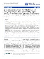
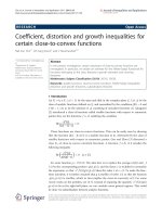
internet. The congestion control algorithms of TCP con-
sists of Slow-Start, Congestion Avoidance, Fast Retrans-
mission and Recovery as shown in Figure 1 in
conjuction with several different timers.
In Slow-Start, the size of congestion window (cwnd)
increases exponentially at the sender whereas in Con-
gestion Avoidance algorithm, cwnd increases linearly.
Fast Retransmission and Recovery algorithm triggers
only when the sender receives three dupacks. As a
result, when the sender receives three dupacks, tradi-
tional TCP assumes that the loss of packets are caused
by network congestion. However, when TCP deployed
in wireless networks, this assumption is no longer t rue.
This is because in wireless networks non-congestion
events are more common than network congestion.
When TCP sender receives three dupacks, the sender
has to consider non-cong estion event s as shown in Fig-
ure 1 in addition to network congestion. If the three
dupacks is due t o packet reordering then the sender
need not retransmit the packets by reducing t he size of
cwnd. On th e other hand, if the three dupacks is caused
by random loss, the sender has to retransmit the packet
without reducing the size of cwnd. Below, we discuss
the main causes of non-congestion events in wireless
networks.
Random Loss
In wireless networks, the loss of packets are due to
transmission errors which is more common than con-
gestion loss. The frequent causes of non-congestion
losses in wireless networks are high bit error rate in the
wireless medium, exposed and hidden terminal pro-
blems, multipath routing, MAC designs etc. [12]. Packet
losses due to channel collision depend on the number
of contention of nodes.
Moreover, in wireless networks, the interferences
between neighboring nodes are much higher compared
to local area networks. As a result, the bit error rates of
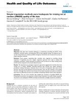
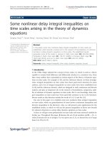
wireless links are more variable in wireless medium. As
shown in Figure 2, TCP sender transmits packet from
P
1
to P
5
. Among that packet P
1
was lost due to trans-
mission error. As a result, the receiver sends three
Sreekumari and Chung EURASIP Journal on Wireless Communications and Networking 2011, 2011:23
/>Page 2 of 20
dupacks by packets P
2
to P
4
. Upon the arrival of three
dupacks the sender trigers fast retransmission unneces-
sarily and retransmits the packet by reducing the size o f
cwnd needlessly and thereby degrade the performance
of TCP.
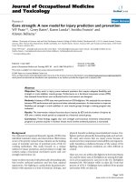
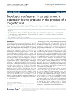
Packet Reordering
Packet reordering [10] refers to the network behavior,
where the relative order of packets is altered when these
packets are transported in the network. As shown in
Figure 3, the packets P
2
,P
3
,P
4
,P
5
,andP
1
are sent in
the order of P
1
,P
2
,P
3
,P
4
,andP
5
. However, the packet
P
1
reaches the destination after the arrival of P
5
.Asa
result, the receiver sends three dupacks of packet P
1
to
the sender. Upon receiving the three dupacks of packet
P
1
, the sender trigers fast retransmission and retransmits
the packet by reducing the size of cwnd needlessly. In
wireless networks, packet reordering may cause due to
route fluttering, inherent parallelism in routers, link-
layer retransmissions, router forwarding lulls, multipath
routing etc. TCP inability to distinguish packet reorder-
ing from packet loss causes unnecessary retransmissions,
slow down the growth of cwnd and reduces the effi-
ciency of the receiving TCP.
For delivering information successfully over wireless
networks, the modification of TCP congestion control
algorithms is necessary especially fast retransmission
and recovery. For the higher performance of TCP over
Figure 1 Congestion control algorithms of TCP.
Figure 2 Fast retransmisssion due to random packet loss.
Sreekumari and Chung EURASIP Journal on Wireless Communications and Networking 2011, 2011:23
/>Page 3 of 20
wireless networks, the sender not only needs to differ-
entiate non-congestion losses from congestion losses but
also need to differentiate the re ordering of packets from
random losses as it is not a rare event in wireless
networks.
Related work
In this section, we describe a set of algorithms that have
been proposed for improving the performance of TCP
that TCP NCE is compared to in this article. ‘Solution s
for random loss’ section gives an overview of thre e ran-
dom loss solutions and ‘Solutions for packet reordering’
section gives an overview of three packet reordering
solutions. In ‘Other solution’ section, we describe TCP
NewReno as it is the most widely deployed protocol in
current internet.
Solutions for random loss
TCP Veno differentiate the random losses from conges -
tion losses by adopting the mechanism of TCP Vegas
[13] to estimate the size of the backlogged packets (N)
in the buffer of the bottleneck link. The calculation of N
is given below.
N
=Diff∗ B
ase
RT
T
(1)
where Diff is the difference between expected and
actual rates and BaseRTT is the minimum measured
round-trip times. The Expected and Actual rates are
measured as,
Expected = cwnd
/
BaseRT
T
(2)
Actual = cwnd
/
RT
T
(3)
where cwnd is t he current size of congestion window
and RTT is the measured smoothed round-trip time.
TCP Veno used the measurement of N to differentiate
the type of packet loss. Specifically, when a packet is
lost, Veno compare the measured value of N with b
(backlog threshold). If N < b,TCPVenoassumesthe
loss to be random rather than congestive, otherwise
Veno assumes the loss to be congestive.
TCP CERL (Congestion Control Enhancement for
Random Loss) distinguishes random losses from conges-
tion losses based on a dynam ic threshold value. TCP
CERL is a sender side modification of TCP Reno. TCP
CERL and TCP Veno are similar in concept. However,
the mechanisms utilized by TCP CERL differ greatly
from those used in TCP Veno. TCP CERL utilizes the
RTT measurements made throughout the duration of
the connection to estimate the queue length (l)ofthe
link, and then estimates the congestion status. The cal-
culation of l is as shown below,
l =
(
RTT − T
)
B
(4)
whereRTTisthemeasuredround-triptime,B the
bandwidth of the bottleneck link, and T the sma llest
RTT observed by the TCP sender and l is updated
with the most recent RTT measurement. Using the
values of l and A (a constant which is equal to 0.55),
TCP CERL used to set the dynamic threshold
value (N),
N = A ∗ l
m
ax
(5)
where l
max
isthelargestvalueoflobservedbythe
sender. If l <N whenapacketlossisdetectedviathree
dupacks, TCP CERL will assume the loss to be random
rather than congestive. Otherwise, TCP CERL will
assume the loss is caused by congestion.
TCP NewJersey introduced as the extension of TCP
Jersey [14] as a router assisted solution for differentiat-
ing random packet loss from congestion loss and react
accordingly. TCP New Jersey ha s two key components
in its scheme, timestamp based available bandwidth esti-
mation (TABE) and congestion warning scheme. To
estimate the available bandwidth, TCP Jersey follows the
same idea of TCP Westwood’s rate estimator to observe
the rate of acknowledged packets by acknowledgments
(ack), but with a different implementation. Upon
Figure 3 Fast retransmisssion due to packet reordering.
Sreekumari and Chung EURASIP Journal on Wireless Communications and Networking 2011, 2011:23
/>Page 4 of 20
receiving n acks, the available bandwidth B
n
is estimated
as shown below.
B
n
=
δ
B
n−1
+L
n
(
t
n
− t
n−1
)
+ δ
(6)
where δ is the TCP’ s estimation of the end-to-end
RTT delay at time t
n
,L
n
the size of the data, t
n-1
the
arrival time of the previous ack, and t
n
the arrival time
of nth packet at the receiver. The sender interpret s the
estimated rate as the optimal congestion window (ownd)
in unit of the size of segment (S) and is calculated as,
ownd =
(
δ ∗ B
n
)
/S
(7)
When the sender receives three dupacks, TCP New-
Jersey checks whether the re ceived ack has congestion
warning mark or not. If it has mark, TCP NewJersey
assumes that the loss is caused by network congestion
and pro ceeds as TCP NewReno [15] after estimating the
available bandwidth for adjusting the size o f cwnd,
whereas, if the ack has no m ark, TCP NewJersey
assumes the loss is due to non-congestion and retrans-
mits the dropped packet without reducing cwnd.
Solutions for packet reordering
RR TCP, the reordering-robust TCP proposed as an
extension of the Blanton-Allman algorithms [16]. RR
TCP is a sender side solution, which adjust the thresh-
old (dupthresh) of dupacks dynamically to detect and
recover from spurious fast retransmissions. However,
this solution differs in three ways compared to Blanton-
Allman algori thm. First, RR TCP uses a different
mechanism to adjust dupthresh dynamically. The author
utilizes a combined cost function for retransmission
timeouts (RTO) and false fast retransmissions to adapt
the false fast retransmit avoidance ratio (FA ratio). Sec-
ond, the authors considered the extended version of the
limited transmi t algorithm [17] which permits a source
to send up to o ne ack-clocked additio nal cwnd’sworth
of data. T hird, for the es timations of RTT and RTO the
authors proposed an idea to correct the sampling bias
against long RTT samples. Compared to Blanton-All-
man algorithm, RR TCP needs excessive computational
and storage overhead.
TCP Persistent packet reordering (TCP PR) proposed
to improve the poor performance of TCP under p ersis-
tent packet reordering by delaying solely on timers. To
detect a p acket loss, TCP PR maintained timers to keep
track of how long ago a packet was transmitted instead
of relying dupacks. When TCP PR detects a packet
drop, the sender reduces the size of cwnd into half and
carried out congestion avoidance algorithm. In order to
avoid the over-reaction to congestion, TCP PR w ill not
reduce the size of cwnd for subsequent occasional
segment drops in the same cwnd. When more than half
of a cwnd’ s worth of pa ckets is detected to be lost,
cwnd is set to one and triggers the slow start algorithm.
One of the major advantages of TCP PR is that it can
able to maintain ack clocking in the presence of packet
reordering. Another merit is the new RTT and RTO
estimator are very effective in packet reordering. How-
ever, TCP PR has some limitations. First, TCP PR is
computationally expensive and second, the new RTT
estimator is overly sensitive to spikes in RTT.
TCP DOOR (Detection of out-of-order and response)
is a state reconciliation m ethod, to solve the perfor-
mance problems caused by spurious retransmissions and
to eliminate the retransmission ambiguity by disabling
the congestion response for a period of time. In order
to detect reorder packets, TCP DOOR insert the
sequence numbers of data and acks on each data pack-
ets and acks, respectively. Upon the detection of out-of-
order events, the sender can either disable the c onges-
tion response or trigger congestion avoidance algorithm.
TCP DOOR detects out-of-order events only after a
route has recovered from failures. As a result, TCP
DOOR is less accurate and responsive than a feed-back
based approach, which can determine whether conges-
tion or route errors occur in a responsive manner.
Other solution
TCP NewReno changes the fast retransmit algorithm for
eliminating Reno’s waiting time for the retransmission
timeout when multiple segments are lost within a single
window. More than 76% of web servers deployed TCP
NewReno as the standard protocol [18]. In fast retrans-
mission, when the sender receives three dupacks the
current implementation of TCP NewReno stores the
highest sequence number transmitted in a variable
‘Recover’ , retransmit the lost se gment and set cwnd to
ssthresh (slow start threshold) plus 3 * mss (maximum
segment size). Then, TCP sender enters into fast recov-
ery and i ncrement cwnd by o ne mss for each additional
dupacks and transmits new packets, if allowed by the
new value of cwnd and the receivers advertised window.
When the sender receives a new ack including Recov er,
the sender sets cwnd to ssthresh and goes to congestion
avoidance state. On the other hand, if this new ack does
not include Reco ver, then the sender consider it as a
partial ack, retransmit the first unacknowledged segment
and add back one mss to cwnd and send a new segment
if permitted by the new value of cwnd. This way, TCP
NewReno can recover mu ltiple packet losses from a sin-
gle window of data. However, TCP NewReno assumes
all duplicate acks are due to the cause of network
congestion.
Opposed to above approaches, TCP NCE is able to
detect, differen tiate and react to non-congestion events
Sreekumari and Chung EURASIP Journal on Wireless Communications and Networking 2011, 2011:23
/>Page 5 of 20
accurately while maintaining responsiveness against
situations with purely congestive loss. TCP NCE can
increase the performance of TCP over wireless networks
by reducing the unnecessary reduction of cwnd size and
spurious retransmissions due to non-congestion events.
TCP NCE
In this section, to tackle the end-to-end performance
degra dation problem of TCP over wireless networks, we
introduce our unified solution named as TCP NCE,
which is capable of reducing the unnecessary re trans-
missions and reduction of cwnd size by detecting, differ-
entiating, and reacting to non-congestion events while
maintaining responsivess against situations with purely
congestive loss. In the following subsections, we describe
the three sc hemes of TCP NCE such as NCE-Detection,
NCE-Differentiation, and NCE-Reaction.
NCE-Detection
For detecting the non-congestion events from network
congestion, we measure the queue length of the bottle-
neck link of a TCP connection. We use a similar
method to that used in [6] for measuring the queue
length. Compared to former method, the main differ-
ence lies in the meas urement of RTT. When computing
the queue length, the estimation o f RTT is important
because RTT includes the delays of forward and reverse
paths. In our scheme, we calculate RTT using the time-
stamp option fields defined in RFC 1323 [19] as shown
in Figure 4. The timestamp option contains two fields
namely, timestamp (TS) value and timestamp echo
reply. Each field has four bytes.
When a segment leaves the sender, the field TSval
stores the current time of sending packet. If that seg-
ment reaches the receiver, it stores the TSval. When the
receiver sends ack, it attaches the time of previously
received segment in the TSe cr field. When the source
receives this ack, it takes the TSecr value and use for
calculating the RTT as shown in (8).
RTT =
cu
rr
e
n
tti
m
e
− T
Secr
(8)
This way of RTT measurement works correctly in the
face of non-congestion events especially in the case of
packet reordering rather than using an algorithm that
samples one RTT p er window of data. The reason is,
in the presence of spurious fast retransmits, TCP is
likely to have to discard most of its potential samples.
As a result, the RTT estimator will not sample the
RTTveryfrequentlyandmaynotkeepagoodestimate
of the RTT [20]. By using the measured RTT, we cal-
culated the queue length (Ql) of the bottleneck link as
shownin(9),
Ql = B
(
RTT
now
− RTT
min
)
(9)
where RTT
now
is the current round-trip time when
the sender receives an ack, RTT
min
is the minimum
RTT observed by the TCP sender, and B is the band-
width of the bottleneck link. As shown in Figure 5,
for detecting the non-congestion events at the time of
receiving the three dupacks, the sender checks the
current queue length which is grea ter than a thresh-
old value. I f it is greater than a threshold value (Th-
Val), the TCP sender confirms that the dupacks is
due to network congestion and proceeds as TCP
NewReno otherwise the sender assumes that the
dupacks is due to n on-congestion events and d elays
the retransmission upto the expiration of dynamic
delay threshold value.
Determination of threshold value
For determining the threshold value in order to detect
non-congestion events from network congestion, we
assume that the router uses drop-tail queueing policy as
it is the most widely deployed router queue manage-
ment scheme [21]. Figure 6 shows the network environ-
ment that we considered for determining the threshold
value. There are ‘ n’ TCP flows from source (S to Sn)
connected to the router R1 and the router R2 connected
tothedestinations(DtoDn).Thecongesteduplink
from R1 and R2 is with capacity C. Based on drop-tail
algorithm, when the queue length becomes equal to the
buffer size (BS), then all the newly arrived packets are
being dropped. As a result, for determining the thresh-
old value we use the percentage of usage buffer size.
However,howmuchpercentageofbuffersizeweneed
to use for determining the threshold value for detecting
non-congestion event from congestion? For that, we
divide the router buffer space into three different loads
Figure 4 TCP Timestamp options.
Sreekumari and Chung EURASIP Journal on Wireless Communications and Networking 2011, 2011:23
/>Page 6 of 20
as shown in Figure 7. It consists of light load, medium
load and heavy load.
When the router buffer space is less than 30%
We consider it as a light load and the router is not con-
gested at this time. As a result, when the sender receives
three dupacks, we can predict that the three dupacks is
due to non-congestion events.
When the router buffer space is less than 90% and
greater than 30%
We consider it as a medium load and the router is not
congested at this time, but it is easy to become con-
gested at the next period of time. In this case a lso, we
can assume that the arrival of three dupacks is due to
non-congestion events.
When the router buffer space is greater than 90%
It means that the router is in the heavy load and it is
under congestion at this time and the buffer will easily
overflow, which results the packet loss due to network
congestion.
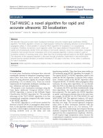
Furthermore, for fixing the threshold value we did
experiments by using different buffer loads in terms of
accuracy as it is the most important performance metric
of both events. Because when accuracy of non-
congestion event increases, obviously the TCP perfor-
mance also increases [22-24] compared to traditional
TCPs. The topology we used for our experiments as
shown in Figure 6. We use TCP connection with 3%
random packet loss and 1% packet reordering with bot-
tleneck capacity 6 Mbps and propagation delay 10 ms.
We measured the accuracy of non-congestion events
(NCE
accuracy
) using equation (10),
NCE
accurac
y
=NCP
exact
/NCP
tota
l
(10)
where NCP
exact
is the number of non-congestion
packets exactly identified as non-congestion events and
NCP
total
is the total number of non-congestion packets
caused by transmission errors and packet reordering.
Figure 8 shows the result of accuracy for varying buffer
loads. It i s evident that when buffer load increases upto
90%, the accuracy of non-congestion e vent becomes
higher. On the other hand, when the buffer load is
greater than 90%, the accuracy of non-congestion event
decreases. Because when the buffer becomes full, all the
incoming packets may drop. As a result, if more than
one TCP connection, all the sender receives three
dupacks and the sender assumes that the packet loss are
due to network congestion even in non-congestion
events and thereby decrease the accuracy. As a result, in
ordertousethebufferresourcesfully,wesetthe
Figure 5 Psuedocode of TCP NCE-Detection of non-congestion events.
Figure 6 Network environment.
Sreekumari and Chung EURASIP Journal on Wireless Communications and Networking 2011, 2011:23
/>Page 7 of 20
thres hold value which is equal to 90% of the buffer size.
Moreover, this value has another advantage. That is,
when the queue length becomes greater than 90% at the
time of receiving three dupacks, we reduce the size of
cwnd and can avoid the loss of multiple packet drops
from different TCP sources due to network congestion.
NCE-Differentia tion
When the sender detects three dupacks is the cause of
non-congestion event, the sender of TCP NCE com-
putes a dynamic delay th reshold (delay-thresh) for dif-
ferentiating whether the received dupacks are due to
random packet loss or p acket reordering and delays the
retransmission upto the expiration of delay-thresh. For
computing the delay-thresh, we need to consider three
things.
(1) If the value of delay-thresh is high, then retrans-
mission timeout ha ppens and the packet gets retrans-
mitted by reducing the size of cwnd to one.
(2) If the value of delay-thresh is too small, then the
TCP will continue to retransmit packets unnecessarily.
(3) If the value of delay-thresh is too high, retrans mis-
sion may not triggered leading to retransmission
timeout.
As a result, by considering these things TCP NCE
computes the best value of delay-thresh by utilizing the
flightsize information of the network. Let ‘Pack
LSent
’ be
the last sent packet from the source and ‘ Pack
LAck
’ be
thelastacknowledgedpacketfromthereceiver.Then
the total number of outstanding packets ‘ Pack
TotNum
’ in
the network at the time of receiving dupacks is calcu-
lated as shown below,
Pack
T
otNu
m
=Pack
L
Se
n
t
−−Pack
LA
ck
(11)
From the total number of outstanding packets in the
network, the sender receives three dupacks. That means
three more packets that has left the network, then the
remaining packets in the network ‘Pack
Remain
’ is,
Pack
Remain
=Pack
TotNum
− ndu
p
ack
s
(12)
After receiving ndupacks which is equal to three, the
sender can expect this much of additional dupacks (add-
dupacks) from the receiver. As a result, we can set the
value of delay-thresh as,
dela
y
-thresh=Pack
Remai
n
(13)
When the sender receives add-dupacks in addition to
first three, which is greater than or equal to the value of
Pack
Remain
, then that add-dupacks are the sign of newly
sent packets. As a result, the TCP sender can confirms
that the corresponding packet is lost from the old win-
dow of data due to transmission errors. Otherwise, the
sender confirms that the add-dupacks were due to reor-
dered packets because if the packet is reordered from
Figure 7 Different buffer loads.
Loads(%)
20 40 60 80 100
Packets
5
10
15
20
25
30
35
40
Accuracy
Figure 8 Accuracy of detecting non-congestion events with different buffer loads.
Sreekumari and Chung EURASIP Journal on Wireless Communications and Networking 2011, 2011:23
/>Page 8 of 20
one window of data, the reordered packet may reach the
destination before the packets from new window of data
reaches the destination [25]. Not only that, the time
taken to reach the newly sent packet to the destination
is much higher than the arrival of the reordered packet
at the destination [26]. As a result, our delay threshold
value helps the TCP to avoid u nnecessary retransmis-
sions and reduction of cwnd.
NCE-Reaction
When the sender receives three dupacks and the current
queue length is less than the threshold value, then the
sender assumes that these dupacks are the sign of non-
congestion events. In this situation, as shown in Figure
9, instead of triggerin g fast retransmission, the sender of
TCP NCE sends a new packet by increment the value of
cwnd to one mss without reducing the size of ssthresh
and computes the retran smission delay-thresh value.
This can maintain the ack clocking. Then the sender
enters into the retransmission delay algorithm and
rec eives add-dupacks. We introduce a new ‘Retransmis-
sion Delay’ algorithm for delaying the retransmission
upto the expiration of dynamic delay-thresh value. As
shown in Figure 10, in retransmission delay, the sender
receives add-dupacks and for each add-dupacks the sen-
der increments the size of cwnd to one mss and send
new packets allowed by the value of cwnd. When add-
dupacks is greater than or equal to the value of delay-
thresh, the sender confirms that the packet is lost due
to transmissio n errors and retransmit the packe t imme-
diately without reducing the size of cwnd and ssthresh.
Otherwise, the sender ignores the add-dupacks and send
packets continuou sly until the size of cwnd greater than
the value of ssthresh.
Figure 11 presents an example of how TCP NCE dif-
ferentiates random loss from reordering of packets.
Consider that seven packets (5 to 11) are sent from a
TCPsendertoaTCPreceiverintheordershownin
Figure 11. Among that, the packet 5 is lost and the sen-
der gets three dupa cks of packet 5 by packets 6, 7, and
8. Consider the three dupacks are due to non-conges-
tion event. As a result, when the sender recei ves three
dupacks, it sends a new packet (12) to the receiver and
computes the delay-thresh value by using the outstand-
ing packets in the network. In this example, the total
number of outst anding packets in the network is 7
using Equation 11. From that, the sender receives three
dupacks and sets the delay-thresh value to 4 using
Equation 12. For each add-dupacks, the sender sends
new packets (13 to 15) allowed by the size of cwn d.
When the newly sent pack et (12) rea ches the destina-
tion, the receiver sent one more add-dupacks to the sen-
der whi ch is greater than or equal to the value of del ay-
thresh. As a result, the sender confirms that the packet
is lost due to transmission error and retransmits the
packet immediately without reducing the size of cwnd.
Otherwise the sender can confirm the packet is reor-
dered and continue sending new packets for every
dupacks until the value of cwnd greater than ssthresh.
This helps the sender to increase the throughput of
TCP by reducing unnecessary retransmissions and win-
dow reductions.
Behavior of TCP NCE
In this subsection, we describe the congestion control
algorithms of TCP NCE and how the TCP sender
behaves upon the arriv al of thre e dupacks. We adopt
the Slow Start (SS) and Congestion Avoidance (CA)
algorithms of original TCP N ewReno. Also, we adopts
the fast retransmission and recovery algo rithms of TCP
NewReno when the sender of TCP NCE detects the
packet losses due to network congestion. At the
Figure 9 Psuedocode of TCP NCE Reaction of detecting non-congestion events.
Sreekumari and Chung EURASIP Journal on Wireless Communications and Networking 2011, 2011:23
/>Page 9 of 20
Figure 10 Psuedocode of Retransmission Delay procedure.
Figure 11 Example of TCP NCE detection of non-congestion event.
Sreekumari and Chung EURASIP Journal on Wireless Communications and Networking 2011, 2011:23
/>Page 10 of 20
beginning of the TCP connection, the sender enters
the SS phase, in w hich the cwnd increases by one mss
for every receiving acks and grows the cwnd
exponentially.
When the value of cwnd reaches the maximum of
ssthresh which is equal to 65535 bytes, the sender
enters the CA phase. During this phase, the sender
increases its cwnd size linearly for every RTT. This lin-
ear growth of transmission rate helps the sender to
slowly probe the available network bandwidth. When
timeout occurs the sender retransmits the packet by
reducing the size of cwnd to one mss and goes to SS
phase as shown in Figure 12. When the sender receives
three dupacks, it checks the current queue length is
greater than threshold v alue. If yes, the senders trig-
gers the fast retransmission algorithm of TCP New-
Reno and retransmit the corresponding packet by
storing the highest sequence number in the variable
‘Recover’ and then enters the fast recovery algorithm.
During fast recovery the sender receives add-dupacks.
For each add-dupacks the sender increments the size
of cwnd by one mss and send new packets allowed by
the value of cwnd. When the sender receives new ack
including the value stored in the varaible Recover, the
sender sets the size of cwnd to the value of ssthresh
and then goes to CA phase. On the other hand, if the
current queue length is less than the threshold value at
the time of receiving three dupacks, the sender sends a
new packet instead of retransmission by incrementing
the size of cwnd to one mss without reducing the size
of ssthresh and triggers the retransmission delay algo-
rithm after computing the delay-thresh for detecting
the non-congestion event whether the three dupacks is
due to random loss or packet reordering. The box with
green lines re presents the procedure of retransmission
delay algorithm. In retransmission delay, the sender
receives add-dupacks and for each add- dupacks the
sender sends new packet allowed by the value of cwnd.
When the add-dupacks greater than or equal to the
value of delay-thresh, the sender retransmit the packet
by keeping the current size of cwnd otherwise the sen-
der continues sending new packets until the value o f
cwnd greater than ssthresh.
Performance evaluation
In this section, we present the performance evaluation
of TCP NCE by showing the metrics such as through-
put, accuracy, and fairness. The below subsections
shows the experimental set up and results o f TCP NCE
compare with other TCP variants.
Figure 12 Behaviour of TCP NCE.
Sreekumari and Chung EURASIP Journal on Wireless Communications and Networking 2011, 2011:23
/>Page 11 of 20
Experimental setup for end-to-end throughput
performance
We have used three different network topologies for
evaluating the performance of TCP NCE throughput in
order to show that our solution is indeed efficient in dif-
ferent network conditions. Simulation topologies are
illustrated in Figure 13. As shown in Figure 13a, in
infrastructure based wireless network, a TCP connection
between sender (S) and receiver (D) are connected to
wired and wireless network a nd is routed through a
base station BS. The wired link between the S and BS
has a bandwidth of 100 Mbps with propagation delay 10
ms. The wireless link between BS and D has a band-
width of 6 Mbps with propagation delay of 50 ms other-
wise noted. On the other hand, i n multi-hop w ireless
network as shown in Figure 13ba TCP connection tra-
verses over fi ve routers R1 to R5 with six hops to the
receiver from sender. Each wireless link has a bandwidth
of6Mbpswithpropagationdelayof10msunless
otherwisestated.InFigure13c,wesimulateadumbell
shaped wireless network with 6 TCP sender (S1 to Sn)
and receivers (D1 to Dn) having one bottleneck link L.
R1 and R2 are two routers with drop-tail queueing pol-
icy. In all simulations, the length of the queue at routers
is set to 50 kbytes and the maximum segment size of
TCP is 512 bytes. The traffic so urce we im plemented
using FTP. The maximum window limit is set to 32
packets. the size of an ack packet is same as the size of
data packet. We enabled the delay ack alogrithm. DSR is
the main routing protocol in our simulation with a max-
imum message buffer size is set to 50 packets. The
duration of our simulations was set to 300 s. During
simulations, data packets are continuously transmitted
upto the end of simulation and the source of all TCP
flows originated from S1 to Sn.Thesimulationshave
been conducted using Qual net version 4.5, a software
that provides scalable simulations of wireless networks.
We compared the throughput with the main TCP ver-
sions and loss differentiation algorithms. The through-
put ‘ t’ is calculated as specified in [27], t = s/stime,
where ‘s’ is the maximum sequence number transmitted
and acknowledged and ‘stime’ is the simulation time.
In order to achieve our aims in the experiment, we
used different scena rios of non-congestion events under
three different network conditions. First condition is
designed to check the throughput of random loss detec-
tion according to the rate of packet loss, bandwidth,
delay, number of hops, and variation of cwnd size.
Thus, in this condition, all packet losses are caused by
transmission errors. The second condition aims to cause
random loss and packet reordering according to the rate
of delay, bandwidth, packet reordering rate, packet loss
rate, and percentage of unneccssary retransmissions.
Finally, in third condition, we planned to observe the
throughput in terms of congestion loss, random loss,
and packet reordering according to the rate of queue
size, bandwidth, packet loss, delay, and number of hops
in order to confirm that TCP NCE is efficient in the co-
existence of congestion and non-congestion events.
Throughput evaluation of TCP NCE under first
condition
In this section, we demonstrate the results of through-
put performance in presence of random loss according
Figure 13 Network topologies for simulation.
Sreekumari and Chung EURASIP Journal on Wireless Communications and Networking 2011, 2011:23
/>Page 12 of 20
to the rate of loss, bandwidth, delay, and cwnd size
using infrastructure based wireless networks. For impos-
ing random loss, we used the exponential error model
available in qualnet. The link-layer retransmission is
enabled and is set to zero. When the retransmission
limit is set to zero there are no reordered packets due
to link-layer retransmissions. Figure 14 shows the result
of throughput in terms of varying loss rates and link
propagation delays. In Figure 14a, t he loss rate ranges
from 0 to 10%. We run seven different simulations. One
with TCP NewReno, one with TCP Veno, one with TCP
CERL, one with RR-TCP, one with TCP-PR, one with
TCP DOOR, and one with TCP NCE. When the per-
centage of packet loss rate increases, the throughput of
all TCP’s decreases. Although the throughput decreas es,
upto 3% all TCP’s have almost similar throughput. But
when the loss rate is greater than 3%, TCP CERL and
TCP NCE begin to increase its throughput compared to
other TCP’s. This is because both of the TCP’ scan
detect and differentiate the random packet losses via
duplicate acknowledgments e ffectively and thus it can
improve the cwnd evolution and thereby gain higher
throughput. However, when the loss rate becomes 7%,
TCP NCE ache ives 85% g reater throughput than TCP
CERL and at 10% loss rate TCP NCE has 50% more
throughp ut gain t han TCP CER L and 85 % more
throughput than TCP NewReno. RR-TCP and TCP-PR
acheives similar connection throughput and TCP DOOR
does not yield any performance gain with respect to the
measurement of congestion control algorithms because
of no out-of-order event is detected. Figure 14b depicts
the result of TCP throughput under varying link propa-
gation delays from 50 to 150 ms in infrastructure wire-
less network with loss rate 2%. As del ay increases, a
larger size of cwnd is needed to utilize the full band-
width of the link. Therefore, the random loss has much
higher impact on the throughput of each TCP as the
propagation delay of the link increases [6]. Among other
TCP’s, TCP NCE acheives higher throughput according
to the increase in link pr opagation delays. This is
because TCP NCE detect the loss by computing the cur-
rent queue length using timestamp based RTT measure-
ment. As a result, even high delay TCP NCE can
accurately detect the type of loss and can trigger t he
congestion control m eachanism accordingly. In the case
of random loss, instead of retransmitting the packet
when the sender recieves three dupacks, TCP N CE
sends new packet without reducing the size of cwnd
and increase the cwnd by one mss for each add-
dupacks. This mechanism hel ps the sender to utilize the
bandwidth efficiently a nd increase the throughput of
TCP.
In Figure 14b at 150 ms delay, TCP NCE acheives
90% higher throughput than TCP NewReno and 81%
higher than TCP CERL throughput. Figure 15 presents
the result of typical variation of TCP throughput under
different bandwidths. In this experiment, we set the
packet loss rate 3% with delay 50 ms. Fro m the gr aph,
we observe that when bandwidth increases, the through-
put also increases. Compared to other TCP’s, TCP NCE
achives the superiority. When bandwidth greater than
12 Mbps, TCP NCE begins to increase the throughput.
This means that TCP NCE can utilize the bandwidth
efficiently. However, in the case TCP Veno, due to fre-
quent timeouts TCP Veno always reduce the size of
cwnd which leads to the degradation of TCP Veno’ s
throughput. In the case of TCP CERL, it missclassifies
some random losses as congestion loss and reduce the
size of cwnd unnecessarily. Moreover, other TCP ’ shas
no mechanism to detect random losses. As a result,
TCP PR, RR TCP, and TCP DOOR frequently reduces
the size of cwnd and thereby decrease the throughput
performance. Figure 16 illustrates the typical cwnd size
of TCP NCE and TCP NewReno according to the
Lossrate(%)
0246810
Throughput(Mbps)
0
1
2
3
4
5
6
TCPNewReno
TCPVeno
TCPCerl
RRTCP
TCPPR
TCPDOOR
TCPNCE
Linkpropagationdelays(ms)
60 80 100 120 140
Throughput(Mbps)
3.0
3.5
4.0
4.5
5.0
5.5
6.0
TCPNewReno
TCPVeno
TCPCerl
RRTCP
TCPPR
TCPDOOR
TCPNCE
(a) (b)
Figure 14 Typical variation in TCP throughput with packet loss rates and link propagation delay.
Sreekumari and Chung EURASIP Journal on Wireless Communications and Networking 2011, 2011:23
/>Page 13 of 20
simulation time. We imposed 3% random loss for this
experiment. In this graph, it is e vident that TCP New-
Reno is always trying to slow down the cwnd even in
random packet loss. On the other hand, TCP NCE
handled the random loss by increasing the size of con-
gestion window. TCP NCE suffers only less time by
reducing the cwnd size compared to TCP NewReno.
Between 10 and 80s, TCP NewReno reduce cwnd more
than 10 times. Opposed to TCP NewReno, TCP NCE
reduced the size of cwnd only three times. The reason
is TCP NCE can able to detect the random loss and is
more effective in utilizing the bandwidth fully.
Throughput evaluation of TCP NCE
under second condition
As we mentioned earlier, the second condition aims to
cause the random loss and packet reordering according
to the rate of delay, bandwidth, packet reo rdering, packet
loss, and percentage of unneccssary retransmissions. For
these experiments, we used multi-hop wireless networks
contains six hops with five routers as shown in Figure
13b. Figure 17 shows the variation in throughput gain
according to packet loss rate and propagation delays at
six hops connection. The packet loss rate ranges from 1
to 5% with 1% packet reorderin g. For causing packet
reordering we used the link-layer retransmission limit
which is equal to three as specified in [28]. As a result,
when high error rate link-layer retransmission cannot
guarantee successful packet retransmission and thereby
reorder the packets in the same flow. We run simulation
with bandwidth 12 Mbps and link propagation delay 50
ms.AsisevidentfromFigure17a,TCPNCEandTCP
CERL perform significantly better than other TCPs. The
throughp ut of RR TCP a nd TCP PR is fl uctuating
according to the incre ase in the loss rat e. When packet
loss rate reaches at 5%, the throughput of TCP NCE has
92% greater than TCP PR and 85 % greater tha n TCP
CERL.
Simulation results in Figure 17b shows that the per-
formance of TCP NCE decreases with increase in propa-
gation delays from 50 to 170 ms. For this exper iment,
we used 9 Mbps bandwidth, 2% random loss, and 4%
packet reorder rate. When the delay increases, a large
size of cwnd is needed to utilize the full bandwidt h of
the lin k. If we compared this results with Figure 17a, we
can see that TCP PR and RR TCP outperfoms TCP
CERL. Because when packet reorder occurs with less
random loss, the solution for packet reordering such as
RR TCP and TCP PR acheives higher th roughput. How-
ever, even in the coexistence of random loss and packet
reordering, TCP NCE achieves significant improvement
in throughput compare to other TCPs by reducing the
frequent reduction of the size of cwnd unnecessarily. As
a result TCP NCE can send more packets and increase
the throughput. Figure 18a depicts the throughput gain
of TCP NCE under varying bandwidths ranges from 9
to 36 Mbps. The loss rate and reorder rate set to 5 and
3%, respectively. As shown in Figure 18a, when band-
width increases, except TCP NCE the throughput of all
other TCP’s fluctuates lightly. When bandwidth reaches
36 Mbps, TCP CERL, TCP PR, TCP NewReno, TCP
DOOR, and TCP Veno acheives only less than 30 Mbps
throughput. Simula tion results in Figure 18b shows the
throughput gain of TCP NCE in presence varying reor-
der rate ranges from 1 to 5%. When reorder rate
increases, the performance of RR TCP, TCP PR, and
TCP DOOR becomes better than TCP Veno, TCP
CERL, and TCP NewReno. However, still TCP NCE has
higher throughput. The ra ndom loss differentiation
algorithms such as TCP CERL and TCP Veno cannot
perform well according to the different reorder rates
because these solutions has no mechanism to detect the
reorder packets and results in the degradation of
Bandwidths(Mbps)
10 15 20 25 30 35
Throughput(Mbps)
5
10
15
20
25
30
35
40
TCPNewReno
TCPVeno
TCPCerl
RRTCP
TCPPR
TCPDOOR
TCPNCE
Figure 15 Typical variation in TCP throughput with different
bandwidths.
Time(s)
0 102030405060708090100110
Congestionwindowsize(Packets)
0
2000
4000
6000
8000
10000
12000
14000
16000
18000
TCPNewReno
TCPNCE
Figure 16 Typical congestion window size of TCP NewReno
and TCP NCE.
Sreekumari and Chung EURASIP Journal on Wireless Communications and Networking 2011, 2011:23
/>Page 14 of 20
throughput. On the other hand, TCP N CE can detect
both the events compared to other TCPs.
In Figure 19, we analyzed the percenta ge of unneces-
sary retransmissions of various algorithms under varying
reorder rate ranges from 1 to 5%. The unnecessary
retransmissions rate, which is defined as the ratio of
unnecessary retransmissions to the total number of
packets transmitted. When the rate of reord er increases,
the unncessary retransmissions of all TCP’ s increases.
However, TCP NCE has less number of retransmissions
compared to other TCP’s due to the ability o f detecting
and differentiating the reorder packets. Compare to
TCP Veno and TCP CERL, TCP PR, RR TCP, and TCP
DOOR has less number retransmissions because of their
capability to f ind the reorder packets. TCP NewReno
has the worst performance. It has two times greater
retransmissions than TCP NCE.
Throughput evaluation of TCP NCE under third
condition
In third condition, we evaluated the throughput perfor-
mance of TCP NCE by imposing congestion loss, ran-
dom loss, and packet reordering in order to c onfirm
that TCP NCE performs well in congestion and non-
congestion events by using dumbell shaped wireless net-
work as shown in Figure 13c. The experiments are
based on different number of TCP connections, queue
size, packet loss rate, reorder rate, unnecessary reduc-
tion of cwnd, and fast retransmissions. Figure 20a pre-
sents the typical throughput performance of TCP’ s
under different number of TCP connections. In this
experiment, all the senders send packets to destinations
using more than one TCP connection ranges from 1 to
20 connections. Apart from that, we use 3% random
loss and reorder rate with bandwidth 24 Mbps and
Lossrate(%)
12345
Throughput(Mb ps )
7.0
7.5
8.0
8.5
9.0
9.5
10.0
TCPNewReno
TCPVeno
TCPCerl
RRTCP
TCPPR
TCPDOOR
TCPNCE
Delays(ms)
60 80 100 120 140 160
Throughput(Mbps)
2.5
3.0
3.5
4.0
4.5
5.0
5.5
6.0
TCPNewReno
TCPVeno
TCPCerl
RRTCP
TCPPR
TCPDOOR
TCPNCE
(a) (b)
Figure 17 Typical TCP throughput according to loss rates and propagation delays.
Bandwidths(Mbps)
10 15 20 25 30 35
Throughput(Mbps)
0
5
10
15
20
25
30
35
TCPNewReno
TCPVeno
TCPCerl
RRTCP
TCPPR
TCPDOOR
TCPNCE
Reorderrate(%)
12345
Throughput(Mbps)
1
2
3
4
5
6
TCPNewReno
TCPVeno
TCPCerl
RRTCP
TCPPR
TCPDOOR
TCPNCE
(a) (b)
Figure 18 Typical TCP throughput according to various bandwidths and reorder rate.
Sreekumari and Chung EURASIP Journal on Wireless Communications and Networking 2011, 2011:23
/>Page 15 of 20
delay 50 ms. Fro m the results of the graph, we can con-
firm that TCP NCE is indeed efficient in all types of
network conditions such as the packet loss and packet
reordering situations. When the number of TCP con-
nections, the throughput of all TCP variants decreases.
Even the throughput decreases, TCP NCE outperforms
more than 70% from TCP CERL and more than 100%
higher throughput than TCP NewReno. Figure 20b
shows the result of throughput gain according to various
queue size from 40 to 80K in bytes. In this graph, it is
evident that the queue utilization of TCP NCE is much
higher than that of other TCP variants and thus TCP
NCE can achieve better throughput.
Figure 21a shows the comparison of TCPs under dif-
ferent bandwidth ranges from 12, 24, and 36 Mbps. In
this experiment, we use five TCP connections from all
senders to different destinations with 2% packet loss
rate and 1% reorder rate with a delay of 80 ms. The
throughput of all TCPs rise steadily according to the
increase in bandwidth. However, TCP NCE has little
more performance improvement compared to other
TCPs.
The unnecessary reduction of the size of cwnd can
be seen in Figure 21b. For this simulation, we use
three TCP connections with 1% of packet reorder
rate and the packet loss rate varies from 5, 7, and 9%
due to network congestion and transmission errors.
When the rate of packet loss increases, the unnces-
sary reduction of c wnd also increases. This leads to
decrease the throughputofTCPs.Amongother
TCPs, TCP NCE has less number of window reduc-
tion. Thus it can send more data and can increase
the throughput. Figure 22 presents the unnecessary
fast retransmissions of all TCP’ s according to the
increase in loss rates which ranges from 5 to 10%.
For doing this simulation, we use the same parameter
settings of former comparison. The unncessary fast
retransmission rate, which is defined as the ratio of
unnecessary fast retransmission to the total number
of packets transmitted. TCP NCE is superior to
others by less number of fast retransmissions. TCP
NCE can limit the retransmission by using the infor-
mation from the network.
Accuracy of TCP NCE
Accuracy is another performance metric we used to
evaluate the performance of TCP NCE. Because accu-
racy is one of the most impor tant metric used in loss
differe ntia tion algorithms for evaluting the performance
in addition to end-to-end throughput. We me asured the
accuracy o f congestion loss (ACL), random loss (ARL),
and packet reordering (APR) where,
ACL =
NCL/NCL
Total
∗ 100
(
ACL ≥ NCL ≥ 0,100% ≥ ACL ≥ 0%
)
where NCL is the number of congestion packet loss
exactly identified as congestion by TCP NCE compare
Reorderrate(%)
12345
Unnecessaryretransmission(Packets)
0
5
10
15
20
25
30
35
TCPNewReno
TCPVeno
TCPCerl
RRTCP
TCPPR
TCPDOOR
TCPNCE
Figure 19 Comparison of unnecessary retransmissions vs
reorder rate.
No:ofconnections
5101520
Throughput(Mbp s)
8
10
12
14
16
18
20
22
24
2
6
TCPNewReno
TCPVeno
TCPCerl
RRTCP
TCPPR
TCPDOOR
TCPNCE
Queuesize(bytes)
40K 50K 60K 70K 80
K
Throughput(Mbps)
10
11
12
13
14
15
16
17
TCPNewReno
TCPVeno
TCPCerl
RRTCP
TCPPR
TCPDOOR
TCPNCE
(a) (b)
Figure 20 Typical TCP throughput according to different TCP connections and queue size.
Sreekumari and Chung EURASIP Journal on Wireless Communications and Networking 2011, 2011:23
/>Page 16 of 20
to other algorithms, and NCL
Total
is the number of
packet loss caused by network congestion.
ARL =
NRL/NRL
Total
∗ 10
0
(
ARL ≥ NRL ≥ 0, 100% ≥ ARL ≥ 0%
)
where NRL is the number of random packet loss
exactly identified as random loss by TCP NCE co mpare
to other algorithms, and NRL
Total
is the number of
packet loss caused by transmission errors.
APR =
NRP/NRP
Total
∗ 10
0
(
APR ≥ NRP ≥ 0, 100
%
≥ APR ≥ 0
%
)
where NRP is the number of reordered packet exactly
identified as packet reordering by TCP NCE compare to
other algorithms, and NRP
Total
is the total number of
reordered packet. Figure 23 presents the simulation
results for checking the accuracy of TCP NCE in terms
of congestion based packet loss with different TCP con-
nections using dumbell shaped wireless network topol-
ogy. We set 1% random loss and packet reorde ring in
order to ch eck the accuracy for the detection of conges-
tion loss. From the graph, it is clear that TCP NCE
gains more than 90% accuracy compared to other
TCP’s. The reason is, TCP NCE can utilize t he maxi-
mum buffer space and this lead s to reduce the missclas-
sification of congestion and non-congestion events.
Figure 24shows the accuracy of random loss by vary-
ing packet loss rates which ranges from 1 to 5%. TCP
NCE, TCP CERL, and TCP Veno has the highest accu-
racy compared to RR TCP, TCP PR, and TCP DOOR.
The reason is these algorithms has no mechanism to
detect random loss. The accuracy of TCP NCE ca used
by packet reordering is depicted in Figure 25. In t his
figure, TCP CERL and TCP Veno has worst perfor-
mance due to the lack of mechanism for detecting the
Bandwidths(Mbps)
15 20 25 30 35
Throughput(Mbps)
5
10
15
20
25
30
35
40
TCPNewReno
TCPVeno
TCPCerl
RRTCP
TCPPR
TCPDOOR
TCPNCE
Lossrate(%)
56789
Unnecessaryreductionofcongestionwindow(packets)
2
4
6
8
10
12
14
16
18
20
22
TCPNewReno
TCPVeno
TCPCerl
RRTCP
TCPPR
TCPDOOR
TCPNCE
(a) (b)
Figure 21 Typi cal TCP throughput according to various bandwidths and comparison of unnecessary reduction of congestion window
size vs loss rate.
Lossrates(%)
5678910
Unncessaryfastretransmissions(Packets)
0
5
10
15
20
25
30
TCPNewReno
TCPVeno
TCPCerl
RRTCP
TCPPR
TCPDOOR
TCPNCE
Figure 22 Comparison of unnecessary retransmission vs loss
rate.
No:ofconnections
6 8 10 12 14 16 18 20
ACL(%)
70
75
80
85
90
95
100
TCPNewReno
TCPVeno
TCPCerl
RRTCP
TCPPR
TCPDOOR
TCPNCE
Figure 23 Accuracy of packet loss due to congestion.
Sreekumari and Chung EURASIP Journal on Wireless Communications and Networking 2011, 2011:23
/>Page 17 of 20
reordering events. However, TCP PR, RR TCP, and TCP
DOOR achieves higher performance when compare to
TCPVenoandTCPCERL.TCPNCEisthesuperior
one among all. Figure 26presents the result of through-
put measurement under varying percentage of accura-
cies. From the figure, we observed that when accuracy
increases, the throughput performance of TCP also
increases. Compared to TCP CERL and T CP PR, TCP
NCE acheives higher throughput when the accuracy
increases.
Fairness of TCP NCE
Fairness is a measure of the relative throughput perfor-
mance of a set of TCP flows of the same type. To inves-
tigate the fairness performance, 10 simultaneous TCP
flows of the same type are run using the dumbell shaped
wireless network topology consisting of 10 TCP sender
and receivers with two bottleneck links L1 and L 2
connected with three routers R1, R2, and R3 as shown
in Figure 27.
We set 9 Mbps bandwidth with 80 ms link porpaga-
tion delay. The throughput of each flow is measured
and calculated the fairness index using the well known
Jain fairness index [29]. Fairness index f(x) is a func tion
of the variability of the throughput across the TCP
flows and can be defined as,
F(x
1
, , x
N
)=
N
i=1
x
i
2
/N ×
N
i=1
(x
i
)
2
where x
i
is equal to the observed throughput of the
ith flow (0 <i ≤ N) normalized to the total achievable
throughput in the link and N is equal to total number
of flows sharing the link. Figure 28 shows the fairness of
TCP NCE compared to other TCPs under varying
packet loss rate ranges from 1 to 5%.
As expected, TCP NCE is more fairer than other algo-
rithms such as TCP NewReno, TCP Veno, TCP CERL,
RR TCP, TCP P R, and TCP DOOR du e to its capability
for detecting and differentiating the non-congestion
events along with congestion and can utilize the band-
width fully.
Conclusion
In this article, for improving the performance of TCP
over wireless networks, we proposed a new unified solu-
tion called TCP NCE, which is capable to reduce the
unnecessary retransmissions and cwnd reductions by
detecting, differentiating and reacting to non-congestion
events such as random losses and packet reordering in
addition to network congesti on losses. For detecting the
congestion from non-congestion events we used the
queue length of the bottleneck link by measuring RTT
Lossrate(%)
12345
ARL(%)
0
20
40
60
80
100
120
TCPNewReno
TCPVeno
TCPCerl
RRTCP
TCPPR
TCPDOOR
TCPNCE
Figure 24 Accuracy of packet loss due to transmission errors.
Reorderrate(%)
12345
APR(%)
0
20
40
60
80
100
120
TCPNewReno
TCPVeno
TCPCerl
RRTCP
TCPPR
TCPDOOR
TCPNCE
Figure 25 Accuracy of packet reordering.
Accuracy(%)
30 40 50 60 70 80 90
Throughput(Mbps)
10
12
14
16
18
20
TCPPR
TCPCerl
TCPNCE
Figure 26 Acuracy vs. throughput.
Sreekumari and Chung EURASIP Journal on Wireless Communications and Networking 2011, 2011:23
/>Page 18 of 20
using TCP timestamp and compared with a threshold
value. For differentiating the non-congestion events, we
used the outstanding packets in the network when the
sender receives t hree dupacks. Furthermore, we intro-
duced a new TCP retransmission algorithm called
‘Retransmis sion Delay’ which guides the TCP sender at
the time of detecting the non-congestion event via three
duplicate acknowle dgments by delaying the r etransmis-
sion upto the expiration of dynamic delay threshold
value. We evaluated the performance of TCP NCE in
terms of throughput, accuracy and fairness over four
different network topologies using qualnet 4.5. The
simulation results have confirmed that TCP NCE has a
significant improvement over existing variants such as
TCP NewReno, TCP Veno, TCP CERL, RR TCP, TCP
PR,andTCPDOOR.ThreesalientfeaturesofTCP
NCE contribute to this improvement. First, detection of
congestion and non-congestion events under different
network conditions. Second, differentiation of these
events and finally, the reaction of TCP sender when
they detect congestion and non-congestion events.
These three features of TCP NCE helps the sender to
reduce the size of cwnd unnecessarily and avoid spur-
ious retransmissions and thereby increase the perfor-
mance of TCP over wireless networks.
List of Abbreviations
ACL: accuracy of congestion loss; ARL: accuracy of random loss; APR:
accuracy of packet reordering; BS: buffer size; CA: Congestion Avoidance;
CERL: Congestion Control Enhancement for Random Loss; cwnd: congestion
window; dupacks: duplicate acknowledgments; NCE-Detection: Detection of
non-congestion events; NCE-Differentiation: Differentiation of non-
congestion events; NCE-Reaction: Reaction to non-congestion events; SS:
Slow Start; TABE: timestamp based available bandwidth estimation; TCP:
Transmission Control Protocol; TCP NCE: TCP for Non-Congestion Events;
TCP PR: TCP Persistent packet reordering; TCP DOOR: Detection of out-of-
order and response.
Acknowledgements
This work was supported by the Grant of Korean Ministry of Education,
Science and Technology (The Regional Core Research Program/Institute of
Logistics Information Technology).
Competing interests
The authors declare that they have no competing interests.
Received: 17 February 2011 Accepted: 29 June 2011
Published: 29 June 2011
References
1. KC Leung, VOK Li, Transmission control protocol (TCP) in wireless networks:
issues, approaches, and challenges. Commun. Surveys Tutorials IEEE. 8(4),
64–79 (2006)
2. M Przybylski, B Belter, A Binczewski, Shall we worry about packet
reordering? in Proceedings of TERENA Networking Conference, Poznan,
Poland, 28–36, June 2005
3. A Sathiaseelan, T Radzik, Reorder Notifying TCP (RN-TCP) with explicit
packet drop notification. Int J Commun Syst. 19(6), 659–678 (2006)
4. K Xu, Y Tian, N Ansari, Improving TCP performance in integrated wireless
communications networks. Comput Netw. 47, 219–237 (2005)
5. CP Fu, SC Liew, TCP Veno, TCP enhancement for transmission over wireless
access networks. IEEE J Select Areas Commun. 21(2), 216–228 (2003)
6. H El-Ocla, TCP CERL: congestion control enhancement over wireless
networks. J Wireless Netw. 16(1), 183–198 (2010)
7. M Zhang, B Karp, S Floyd, L Peterson, RR-TCP: a reordering-robust TCP with
DSACK, in Proceedings of IEEE International Conference on Network Protocols
(ICNP ‘03),95–106, November 2003
8. S Bohacek, JP Hespanha, J Lee, C Lim, K Obraczka, A new TCP for persistent
packet reordering. IEEE/ACM Trans Netw. 14(2), 369–382 (2006)
Figure 27 Dumbell shaped fully wireless network with two bottleneck links.
Lossrate(%)
12345
Fairness(x)
0.94
0.95
0.96
0.97
0.98
0.99
1.00
1.01
TCPNewReno
TCPVeno
TCPCerl
RRTCP
TCPPR
TCPDOOR
TCPNCE
Figure 28 Fairness of TCP NCE towards other TCP algorithms.
Sreekumari and Chung EURASIP Journal on Wireless Communications and Networking 2011, 2011:23
/>Page 19 of 20
9. F Wang, Y Zhang, Improving TCP performance over mobile ad-hoc
networks with out-of-order detection and response. in Proceedings of ACM
MOBIHOC 2002, Lausanne, Switzerland, 9-11, 217–225, June 2002
10. KC Leung, V Li, D Yang, An overview of packet reordering in transmission
control protocol (TCP): problems, solutions, and challenges. Parallel Distrib
Syst IEEE Trans. 18(4), 522–535 (2007)
11. Scalable Networks, />12. LP Tung, WK Shih, TCP throughput enhancement over wireless mesh
network. IEEE Commun Mag. (2007)
13. LS Brakmo, S O’Malley, LL Peterson, TCP Vegas: New techniques for
congestion detection and avoidance. Comput Commun Rev. 24(4), 24–35
(1994)
14. K Xu, Y Tian, N Ansari, TCP-Jersey for wireless IP communications. IEEE J
Select Areas Commun. 22, 747–756 (2004)
15. S Floyd, T Henderson, The new Reno modification to TCP’S fast recovery
algorithm. RFC 2582 (1999)
16. E Blanton, M Allman, On making TCP more robust to packet reordering.
ACM SIGCOMM Comput Commun Rev. 32(1), 20–30 (2002)
17. M Allman, H Balakrishnan, S Floyd, Enhancing TCP’s loss recovery using
limited transmit. IETF RFC, Network Working Group, January 2001
18. A Medina, M Allman, S Floyd, Measuring the Evolution of transport
protocols in the internet. ACM SIGCOMM Comput Commun. 35,37–52
(2005)
19. V Jacobson, R Braden, D Borman, TCP extensions for high performance. RFC
1323 (1992)
20. J Feng, Z Quyang, L Xu, B Ramamurthy, Packet Reordering in high-speed
networks and its impact on high-speed TCP variants. Comput Commun. 32,
62–68 (2009)
21. T Reddy, A Ahammed, R Banu, Performance comparison of active queue
management techniques. IJCSNS Int J Comput Sci Netw Security. 9(2),
405–408 (2009)
22. MY Park, SH Chung, S Prasanthi, End-to-end loss differentiation algorithm
based on estimation of queue usage in multi-hop wireless networks. IEICE
Trans Inf Syst. E92-D(10), 2082–2093 (2009)
23. CH Lim, JW Jang, Robust end-to-end loss differentiation scheme for
transport control protocol over wired/wireless networks. IET Commun. 2,
284–291 (2008)
24. S Cen, PC Cosman, GM Voelker, End-to-end differentiation of congestion
and wireless losses. IEEE/ACM Trans Netw. 11(5), 703–717 (2003)
25. J Feng, Z Quyang, L Xu, B Ramamurthy, Packet reordering in high-speed
networks and its impact on high-speed TCP variants. Comput Commun. 32,
62–68 (2009)
26. Y Wang, G Lu, X Li, A study of internet packet reordering, in Proceedings of
Information Networking Technologies for Broadband and Mobile Networks
International Conference, ICOIN 2004, Busan, Korea, 18
–20, February 2004
27. R De Oliveira, T Braun, A smart TCP acknowledgment approach for
multihop wireless networks. Mobile Comput IEEE Trans. 6(2), 192–205 (2007)
28. D Yang, KC Leung, VOK Li, Simulation-based comparisons of solutions for
TCP packet reordering in wireless networks, in Wireless Communications and
Networking Conference, 2007. WCNC 2007. IEEE, 11-15, 3238–3243, March 2007
29. R Jain, D Chiu, W Hawe, A quantitative measure of fairness and
discrimination for resource allocation in shared computer systems. Research
Report TR-301. (1984)
doi:10.1186/1687-1499-2011-23
Cite this article as: Sreekumari and Chung: TCP NCE: A unified solution
for non-congestion events to improve the performance of TCP over
wireless networks. EURASIP Journal on Wireless Communications and
Networking 2011 2011:23.
Submit your manuscript to a
journal and benefi t from:
7 Convenient online submission
7 Rigorous peer review
7 Immediate publication on acceptance
7 Open access: articles freely available online
7 High visibility within the fi eld
7 Retaining the copyright to your article
Submit your next manuscript at 7 springeropen.com
Sreekumari and Chung EURASIP Journal on Wireless Communications and Networking 2011, 2011:23
/>Page 20 of 20