báo cáo hóa học: " Low latency IP mobility management: protocol and analysis" pot
Bạn đang xem bản rút gọn của tài liệu. Xem và tải ngay bản đầy đủ của tài liệu tại đây (619.44 KB, 16 trang )
RESEARC H Open Access
Low latency IP mobility management: protocol
and analysis
Min Liu
1*
, Xiaobing Guo
2,1,4
, Anfu Zhou
1
, Shengling Wang
1
, Zhongcheng Li
1
and Eryk Dutkiewicz
3
Abstract
Mobile IP is one of the dominating protocols that enable a mobile node to remain reachable while moving
around in the Internet. However, it suffers from long handoff latency and route inefficiency. In this article, we
present a novel distributed mobility management architectur e, ADA (Asymmetric Double-Agents), which introduces
double mobility agents to serve one end-to-end communication. One mobility agent is located close to the MN
and the other close to the CN. ADA can achieve both low handoff latency and low transmission latency, which is
crucial for improvement of user perceived QoS. It also provides an easy-to-use mechanism for MNs to manage and
control each traffic session with a different policy and provide specific QoS support. We apply ADA to MIPv6
communications and present a detailed protocol design. Subsequently, we propose an analytical framework for
systematic and thorough performance evaluation of mobile IP-based mobility management protocols. Equipped
with this model, we analyze the handoff latency, singl e interaction delay and total time cost under the
bidirectional tunneling mode and the route optimization mode for MIPv6, HMIPv6, CNLP, and ADA. Through both
quantitative analysis and NS2-based simulations, we show that ADA significantly outperforms the existing mobility
management protocols.
Introduction
Next-generation wireless networks (NGWN) are envi-
saged to have an all-IP-based infrastructure with the
support of heterogeneous wireless access tec hnologie s.
Mobility management with provision of seamless hand-
off is crucial for an efficient support of global roaming
of mobile nodes in NGWN [1]. Mobility m anagement
addresses two main problems: location management and
handoff management [2]. Location management enables
a network to discover the current point of attachment
of mobile terminals for successful information delivery.
Handoff management maintains the active connections
for roaming mobile terminals as they change their
points of attachment to the network.
Mobile IP enables an IP node to maintain its connec-
tivity to the Internet when roaming among differe nt
access networks, and is expected to be the main engine
for IP layer mobility management in the next generation
net works. However, it suffers from long handoff latency
and inefficient route problems.
Prolonged handoff latency
Mobile IP requires that a home agent (HA) be notified
of every location change of the mobile node (MN). This
causes unnecessary signaling overhead and handoff
latency, especially for MNs with relatively high mobility
and long distance to the ir HAs. In addition, congestion
is likely to arise in the home network and the HA will
be the bottleneck point of such congestion.
Inefficient route
When an MN moves to a foreign domain, all packets
senttotheMNhavetobetunneledthroughitsHA
along paths that are usually longer than the optimal
end-to-end path. The triangular route will cause high
transmission delay and congestion in the home network.
This problem is especially serious when the MN stays in
a remote foreign domain for a long period of time.
Many IP-based micro-mobility management protocols
[3-8] have been proposed to reduce handoff latency in
mobile IP. Their basic idea is that the majority of user’s
mobility is local and can be limited in a ‘domain’ by
introducing the notion of hierarchy. Although these
solutions achieve reduction in signaling load and hand-
off latency during movements within one domain, they
* Correspondence:
1
Institute of Computing Technology, Chinese Academy of Sciences, Beijing,
100190, People’s Republic of China
Full list of author information is available at the end of the article
Liu et al. EURASIP Journal on Wireless Communications and Networking 2011, 2011:25
/>© 2011 Liu et al; licensee Springer. This is an Open Access article distributed under the terms of the Creative Commons Attribution
License ( which permits unrestricted use, distribution, and reproduction in any mediu m,
provided the original work is pro perly cited.
have high signaling load and long handoff latency for
inter-domain roaming . In addition, these protocol s can-
not alleviate the triangular route problem.
The problem of triangular routing can be solved by
route optimization [9]. The basic idea behind route opti-
mization is to use a direct route between MNs and their
correspondent nodes (CNs) to bypass the HA. Each CN
maintai ns an address binding cache of the MN and tun-
nels the packets directly to the care-of address (CoA) of
the MN. In mobile IPv6 (MIPv6) [10], route optimiza-
tion has been proposed as a fundamental component,
rather than a non-standard set of extensions as in
mobile IPv4 (MIPv4) [11]. The major drawback of such
a solution is that it also needs the CNs to support rout-
ing optimization. In addition, a host needs to differenti-
ate and treat a peer fixed host and a peer mobile host
different ly. Moreover, route optimization may cause ser-
ious security problems.
Although there are many extensions to enhance
mobile IP-based mobility management protocols, they
often fail to simultaneously solve the prolonged handoff
latency and inefficient route problems.
In this article, we present a novel distributed mobility
management architecture, ADA, which introduces two
asymmetric mobility agents to solve the above two pro-
blems. One mobility agent is located close to the MN
and acts as a local HA to limit the amount of signaling
traffic outside the local domain. The other is located
close to the CN and its major objective is to shorten the
distance between the CN and the MN’sHAsoasto
minimize routing overheads. ADA is proposed for low
latency mobility management, including low handoff
latency and low transmission latency, which are critical
for improvement of user perceived Qo S. ADA also
makes it possible for MNs to manage and control each
traffic session with a different policy based on practical
application requirements and network environments. It
is also convenient for the CN-locat ed network to moni-
tor and control in-bound and out-bound traffic and pro-
vide specific QoS support.
It should be noted that ADA is an extension to the
mobile IP-based mobility management architecture and
can be applied to both MIPv4 and MIPv6. In this article,
we apply ADA to MIPv6 communications and design
the corresponding protocol operations. Subsequently, we
propose an analytical framework for systematic and
thorough performance evaluation of mobile IP-based
mobility management protocols. This framework can be
used to provide guidelines for decision making of mobi-
lity management protocols in various network environ-
ments. Equipped with the proposed model, we derive
and analyze the handoff latency, single interaction delay,
and total time cost for specific application traffic for
MIPv6, HMIPv6 [12], CNLP [13], and ADA. We also
evaluate the performance gain of these protocols by
NS2-based simulations.
The remainder of the article is structured as follows.
‘Related work’ section offers a brief overview of related
work. ‘ Asymmetric double mobility agents for lo w
latency mobility management’ section introduces the
basic idea of ADA. ‘Application of ADA to mobile IPv6
communications’ section applies ADA to MIPv6 com-
munications and presents the detailed protocol design.
‘Performance analysis’ section proposes an analytical fra-
mework for performance evaluation of mobile IP-based
mobility management protocols. ‘Performance evalua-
tion’ section verifies the feasibility and effectiveness of
ADA by quantitative analysis and NS2-based simula-
tions. The article is concluded in ‘Conclusions’ section.
Related work
One of the research challenges for next generation all-
IP-based wireless systems is the design of intelligent
mobility management techniques that take advantage of
IP-based technologies to achieve global roaming among
various access technologies [14]. Existing improvement
work on mobile IP-based mobility management can be
classified into two main categories: (1) those aiming to
reduce handoff latency, and (2) those aiming to improve
route efficiency.
Approaches to reduce handoff latency
Hierarchical mobile IP [3] and other micro-mobilit y
protocols such as cellular IP [4], IDMP [5], and
HAWAII [6] have been proposed to achieve reduction
in handoff latency. These mechanisms introduce
another layer of hierarchy to the base MIPv4 architec-
ture to localize the signaling messages to one domain.
Hierarchical mobile IP [3] introduces a mobility agent
called gateway foreign agent (GFA). When an MN
changes a foreign agent (FA) within the same regional
network, it does not need to register with its HA.
Instead, it performs a regional registration to the GFA
to update its CoA. This centralized system architecture
is sensitive to the GFAs failure and cause a h igh traffic
load on GFAs [15].
The authors in [7] propose a distributed GFA manage-
ment scheme where each FA can function either as an
ordinary FA or a GFA. Whether an agent should act as
an FA or as a GFA depends on user mobility. Thus, the
traffic load in a regional network is evenly distributed to
each FA. The authors also propose a dynamic scheme
which is able to adjust the number of FAs under a GFA
for each MN according to the user-variant and time-var-
iant user parameters. In this system, there is no fixed
regional network boundary for ea ch MN. An MN deci-
deswhentoperformahomelocationupdateaccording
to its changing mobility and packet arrival pattern.
Liu et al. EURASIP Journal on Wireless Communications and Networking 2011, 2011:25
/>Page 2 of 16
The authors in [8] propose another dynamic hierarchi-
cal mobility management scheme for MIPv4 networks.
In this scheme, when an MN changes its subnet and
obtains a new CoA from the new FA, the new FA
updates the new address to the MN’spreviousFAso
that the new FA forms a new location management
hierarchical level for that user. Packets to be delivered
to the MN can be tunneled via the multiple levels of
FAs. In order to avoid long packet delivery delays, there
is an optimal level number for the hierarchy for each
user according to his/her call-to-mobility ratio. The
threshold can be dynamically adjusted based on the up-
to-date mobility and traffic load for each terminal.
When the threshold is reached, the MN performs a
home registration and sets up a new hierarchy for its
further movements.
The authors in [16] present a mailbox-based MIPv4
scheme. A sender sends packets to the receiver ’ s mail-
box which will in turn forward them to the destination.
During each handoff, a choice can be made on whether
to report this handoff to the HA or simply t o the m ail-
box. In this way, the worklo ad on the HA as well as the
registration delay c an be reduced. When the MN
migrates to a foreign network, it sends a registration
message to the old FA where its mailbox resides. The
old FA then decides whether to move the mailbox to
the new FA. Separating the mailbox from its owner can
help to enable dynamic t radeoff between the packet
delivery cost and the registration cost. The mailbox
scheme requires FAs to maintain a large amount of
informa tion about MNs. It also calls for the information
exchange between the old FA, the new FA, and the HA.
MIPv6 [10] shares many features with MIPv4 [11], but
it is integrated into IPv6 and offers many other
improvements. In MIPv6, there is no need to deploy
specia l routers as FAs as in MIPv4. As a result, mobility
management schemes based on extensions to FAs
[7,8,16] cannot work in MIPv6 networks.
HMIPv6 [12] introduces a new Mob ile IPv6 node,
called the mobility anchor point (MAP), to limit the
amount of MIPv6 signaling traffic outside the local
domain. An MN entering a MAP domain can bind its
current location, on-link care-of address (LCoA), with
an address on the MAP’ s subnet, regional care-of
address (RCoA). If the MN changes its current address
within a MAP domain, it only needs to register the new
address with the MAP. Hence, only the RCoA needs to
be registered with the CNs and the HA. Although
HMIPv6 can help to reduce long handoff latency and
excessive sig naling traf fic associated wit h MIPv6 during
intra-domain handoff, it is not effective when MNs
move across MAP domains.
FMIPv6 [17] is another enhancement of MIPv6, which
aims to improve handoff latency by delivering packets to
the new point of attachment at the earliest opportunity.
It does so by obtaining link-layer information (L2 trig-
ger) to forecast handoff events and by enabling the MN
to get the new access point and the associated subnet
prefix information when the MN is still connected to its
current subnet. FMIPv6 requires information exchange
and packets forwarding between the previous access
router (PAR) and the new access router (NAR) to
reduce handoff latency and packets loss. This requires
major modifications to the existing infrastructure.
Approaches to improve route efficiency
Route optimization [9] has been proposed to alleviate
the triangular routing problem in MIPv4 [11]. In MIPv6
[10], route optimization has been proposed as a funda-
men tal component. In the rou te optimization approach,
an MN is allowed to notify a CN directly of its current
address. Thus, packets from the CN can be routed
directly to the CoA of the MN. However, CN modifica-
tion is needed to achieve the optimization, therefore this
approach is difficult to deploy. In addition, route optimi-
zation may cause serious security problems.
Authors in [18] present a new scheme for reducing
link and signaling costs in route optimiza tion. Link and
signaling cost functions are introduced to capture the
tradeoff between the network resources consumed by
the routing path and the signaling a nd processing load
incurred by route optimization. A Markovian decision
model is presented in [18] to find an optimal sequence
for route optimization.
Authors in [19] address the triangular routing problem
by proposing a new entity, temporary home agent (TA),
to serve the MN in foreign networks. When an MN
enters a foreign network, a TA in the foreign network is
dynamically sel ected. The TA allocat es a temporary
home address (THAddr)fortheMN.TheMNthen
uses the THAddr as its source address when i nitiating
new connections. The underlying objective is to shorten
the distance between an MN and its HA so as to reduce
handoff latency and improve routing efficiency. How-
ever, the on-going connections established in previous
domains with the old TAs are still served by those TAs.
In this case, triangular routes still exist. The proposed
TA protocol mainly deals with out-bound connections
(from MNs to CNs). For in-bound connections, one
may resort to mobile IP.
Authors in [20] propose a session-layer-based mobility
architecture called DHARMA, whose aim is to shield
the transport layer or application layer protocols from
the effects of intermittent connectivity. DHARMA uses
the PlanetLab overlay network to select a HA close to
the CN from a distributed set of HAs.
CNLP [13] is a mechanism to achieve simultaneous
optimized routing and correspondent node-targeted
Liu et al. EURASIP Journal on Wireless Communications and Networking 2011, 2011:25
/>Page 3 of 16
location privacy. In CNLP, a home agent, as specified in
MIPv6, is called IP reachability home agent (IRHA) and
thehomeaddressthatisregisteredattheIRHAis
referred to as home address for IP reachability
(HoA_IR). In addition to IRHA, CNLP introduces a new
entity, optimized routing home agent (ORHA), which is
located topologically close to the CN and is used for
optimized communication with this CN. A home
address that is registered at the ORHA is called home
address for optimized routing (HoA_OR). For mobile
node-initiated sessions, the MN uses the O RHA as the
home agent and HoA_OR on higher layers. Because the
ORHA is near the C N, CNLP reduces the transmission
delay and improves route efficiency. However, CNLP
cannot improve handoff latency, especially when the
MN is far away from the CN.
Performance evaluation of IP-based mobility
management schemes
Although there has been a lot of research focusing on
IP-based mobility management protocols, performance
evaluation of these protocols is mainly based on simula-
tion and testbed approaches [21,22]. Also, the scenarios
used for simulations in different papers are quite differ-
ent, thus the comparison of IP-based mobility manage-
ment protocols is hardly possible.
Little work is available in the literature which assesses
IP-based mobility management protocols through analy-
tical models. Current analytical models are of ten based
on simple assumptions and have some drawbacks [1].
Authors in [23] present a simple analytical model to
study the handoff latency of IPv6-based mobility proto-
cols within the framework of the EU IST project Moby
Dick. Its aim is to assess the most appropriate scheme
for its functional specification and implementation.
Signaling load to support mobility (i.e., the bandwidth
used by control messages) is analyzed according to bind-
ing update (BU) emission frequency in [24].
Authors in [25] analyze the overhead associated with
FMIPv6 including the signaling cost and the packet
delivery cost. They also compare FMIPv6 with MIPv6 in
terms of packet loss rates and buffer requirements.
However, handoff latency and the impact of user mobi-
lity models are not investigated.
Analytical models for performance evaluation of
HMIPv6 in IP-based cellular networks are proposed in
[26]. These are based on random-walk and fluid-flow
models. Based on the proposed models, the authors ana-
lyze the impact of cell residence time and user popula-
tion on the location update cost and the packet delivery
cost.
In [1] the effects of network parameters, such as sub-
net residence time, packet arrival rate and wire less link
delay, are investigated for performance evaluation of
MIPv6, HMIPv6, F MIPv6, and F-HMIPv6 [27] with
respect to various metrics such as signaling overhead
cost, handoff latency, and packet loss. Numerical resul ts
in [1] show that there is a trade-off between these per-
formance metrics and network parameters. However,
single interaction delay and total time cost for specific
application traffic were not investigated.
Asymmetric double mobility agents for low
latency mobility management
In this section, we present a novel distributed mobility
management architecture, ADA (asymmetric double-
agents), which can achieve both low handoff latency and
low transmission latency in mobility management.
In this architecture, there are two asymmetric mobility
agents to serve one end-to-end communication. One
mobility agent is located close to the MN and is referred
to as local mobile proxy ( LMP). The other is located
close to the CN and is referred to as correspondent
mobile proxy (CMP).
The network architect ure shown in Figure 1 illustrates
an example of the use of ADA.
The aim of ADA is to enhance performance of Mobile
IP while minimizing the impact on mobile IP or other
mobile IP based protocols. ADA introduces two new
network entities (the LMP and CMP ), and mino r exten-
sions to the MN operations. The CN and HA operations
willnotbeaffected.Itispertinenttonotethattheuse
of ADA does not rely on, or assume the presence of, a
permanent home agent. In other words, a mobile node
need not have a permanent home address or home
agent in order to be ADA-aware or use the fea tures in
ADA.
Figure 1 ADA network architecture.
Liu et al. EURASIP Journal on Wireless Communications and Networking 2011, 2011:25
/>Page 4 of 16
Some important terminologies in ADA are defined as
follows.
Local Mobile Proxy (LMP): An LMP is essentially a
local home agent. The function of the LMP is like that
of the GFA in hierarchical mobile IP [3] and MAP in
hierarchical mobile IPv6 [12]. Its aim is to classify the
movement of mobile users into macro-mobility and
micro-mobility, and provide local mobility handling. By
limiting the regional handoff process and signaling traf-
fic to the local domain, the LMP helps to reduce the
handof f latenc y and signaling overhead. Compared with
GFA and MAP, the traffic load of the LMP will be alle-
viated significantly as a result of the CMP’s participa-
tion. However, the LMP need not have any knowledge
of the MN’s CMP. In other words, the existence of the
CMP is transparent to the LMP. As a resu lt, the LMP
can work independently. In this scenario, ADA will
degenerate to general hierarchical Mobile IP solution.
Correspondent Mobile Proxy (CMP): A CMP is essen-
tially a locality-optimized home agent. For every com-
munication, ADA dynamically selects a CMP located
topologically close to the CN. Like the ORHA in CNLP,
the major objective of the CMP in ADA is to shorten
the distance between the CN and the MN’sHAsoasto
minimize routing overheads. However, because of the
design aims of ADA (not only to reduce routing over-
heads but also to shorten handoff latency) and its spe-
cial double agents architecture, the operation procedure
and signaling structure of the CMP are totally different
fromthoseintheORHA.InADA,theCMPshouldbe
able to accept registrations from the MN that indicate
its LMP information.
Distributed home address (DHoA): A DHoA is a
home address allocated by the CMP to the MN.
With the function of the LMP, ADA reduces the
handoff latency and signaling overhead associated with
mobile IP during handoff within one domain. In addi-
tion, because the CMP is near the CN, ADA can pro-
vide efficient route for all CNs including those that do
not support route optimization.
An ADA-aware MN can choose whether to use the
CMP for a connection based on the application type
and the expected communication traffic. During the
communication with the CN, if the MN changes its cur-
rent address, the MN can decide whether to info rm the
corresponding CMP to update its CoA based on the
requirement of th e current communication and the net-
work environment of the new link. The MN can choose
to update the bindings in only a certain set of CMPs
and thus only maintain the communications with the
corresponding CNs. This provides an easy-to-use
mechanism for MNs to manage and control each traffic
session with a different policy based on practical appli-
cation requirements and network environments.
Generally, sessions that need to be maintained during
the MN’s mobility are mainly the client-server types
where the CNs are servers. Many applications, such as
video on demand, e-mail retrieval, file downloading, fall
in this category [19]. ADA is well-suited for this case
and can help such CNs enhance their support for their
clients’ mobility without any change to the CN’simple-
mentation. It is also convenient for the CN-lo cated net-
work to monitor and c ontrol in-bound and out-bound
traffic, and provide specific QoS support. For example,
an ISP ca n set a policy on its CMP to control the maxi-
mum number of roaming users. The introduction of the
CMP not only allows the shortest communication path
to be used, but also eliminates congestion at the MN’s
HA and home link. In addition, the impact of any possi-
ble failures of the HA and home link on the path to or
from the MN is reduced.
ADA introduces a small amount of additional state for
each CN’s CMP, some additional messaging, and a little
time delay before it can be turned on for a new connec-
tion. However, it is believed that in most cases the bene-
fits far outweigh the costs. In ‘Performance evaluation’
section, we will evaluate performance of ADA through
both quantitative analysis and NS2-based simulations.
Application of ADA to mobile IPv6 communications
ADA is an extension to the mobile IP-based mobility
management architecture and can be applied to both
MIPv4 and MIPv6. In this section, we apply ADA to
MIPv6 communications and present the detailed proto-
col design.
In order to keep the maximum compatibility to
existing protocols, when applied to MIPv6, the func-
tion of the LMP in ADA is the same as that of the
MAP in HMIPv6. No signal is added and no operation
is changed. As a result, ADA can be compatible with
both MIPv6 and HMIPv6. ADA c an also work with
other micro-mobility proto cols. For example, when
applied to M IPv4, we can use the GFA as the LMP, so
that ADA can be compatible with hierarchical mobile
IP either.
Next,wepresentthedetailedoperationsofADA
when applied to MIPv6 in the bidirectional tunneling
(BT) mode and route optimization (RO) mode, respec-
tively. Only the incremental modifications compared
with the standard HMIPv6 and MIPv6 protocols are dis-
cussed. As the function of the LMP is the same as that
of the MAP, in the following description, we will use
MAP instead of LMP. The terms RCoA, LCoA, BU, BA,
LBU in ADA are defined the same as in HMIPv6. Com-
pared with HMIPv6, there is one ty pe of special binding
update in ADA: CMP binding upd ate (CBU). There are
two types of CB U: CBU-L and CBU-R. The MN sends a
CBU-L to the CM P in order to establish a binding
Liu et al. EURASIP Journal on Wireless Communications and Networking 2011, 2011:25
/>Page 5 of 16
betweentheDHoAandLCoA,whileaCBU-Risused
to establish a binding between the DHoA and RCoA.
Bidirectional tunneling mode
Connection initiation process
If the MN wants to initiate a session with ADA support,
it should firstly tr y to discover a CMP in the CN’ s
domain. The pr ocess is similar to the mechanism,
known as ‘location-dependent home agent discovery’ in
[13]. If the discovery is successful, the MN will boot-
strap with the CMP using the mechanisms specified in
[28]. During the bootstrapping process, the CMP will
establish a binding between the DHoA and LCoA. Then
the MN can communicate with the CN through the
CMP in BT mode. At the same time, the MN will send
a CBU-R to the CMP to bind the MN’sDHoAtoits
RCoA. The LCoA is used as the source address of the
CBU-R.
Actually, many options can be proposed to implement
the discovery of a CMP and the assignme nt of a DHoA.
In this article, we assume the connection initiation pro-
cess of ADA in BT mode will take two Round-Trip
Times (RTTs) between the MN and the CMP.
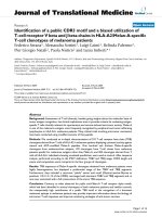
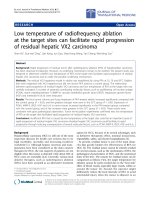
Intra-domain handoff process
The intra-domain handoff process of ADA in BT mode
is shown in Figure 2, where the broken line indicates
that the packet is sent in parallel with the previous one
and the gray bol d line indicates that the pa cket is the
same as in HMIPv6. In Figure 2 and the following flow
diagrams, we indicate the source address of some pack-
ets by brackets. For example, (LCoA) data means that
the source address of the data is LCoA.
When the MN moves within the same MAP domain,
it should send (in parallel) a LBU message to the MAP
and a CBU-L message to the CMP to register its new
LCoA. In this case, the RCoA remains unchanged.
When receiving the BA from the MAP, the MN can
resume its communication with the CN through the
MAP and the CMP. After receiving the BA from the
CMP, the MN can communicate with the CN through
the CMP without the transfer of the MAP.
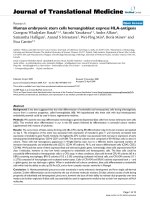
Inter-domain handoff process
The inter-domain handoff process of ADA in BT mode
is shown in Figure 3. The RA used to detect move-
ment will also inform the MN whether it is still in the
same MAP domain. If a change in the advertised
MAP’s address is received, the MN needs to configure
two new CoAs: an RCoA on the MAP’ slinkandan
LCoA. Then the MN will send the MAP an LBU to
bind its RCoA to LCoA. At the same time, a CBU-L
will be sent to the CMP to register the MN’ snew
LCoA. When receiving the BA from the CMP, the MN
can resume its communication with the CN through
the CMP. After receiving the BA from the MAP, the
MN will register its RCoA with the CMP by sending it
aCBU-R.
Route optimization mode
As the CMP is located close to the CN, ADA can pro-
vide an effi cient route e ven in the bidirectional tunnel-
ing mode. Thus, although ADA supports the route
optimization mode, it is only recommended for commu-
nications with a large amount of traffic.
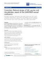
Connection initiation process
As shown in Figure 4, the connection initiation process
of ADA in the RO mode is an extension to the BT
mode. In Figure 4, the CMP discovery and bootstrap-
ping processes have been omitted. After bootstrapping,
the MN can communicate with the CN through the
CMP in BT mode. At the same time, the MN will send
a CBU-R to the CMP to bind the MN’sDHoAtoits
RCoA. Simultaneously, the MN sends (in parallel) a
home test init (HoTI) message through the CMP to the
CN and a care-of test init (CoTI) message directly to
the CN. The CN will respond with home test (HoT)
and care-of test (CoT), respectively. Upon successfully
completing this return routability (RR) procedure, a BU
will be sent to the CN to register the MN’sLCoA.
Meanwhile, when the MN receives the BA from the
CMP for CBU-R, it will initiate another RR procedure.
In this RR procedure, the MN sends a HoTI message
through the MAP and the CMP to the CN and a CoTI
Figure 2 Intra-domain handoff process of ADA in BT mode. Figure 3 Inter-domain handoff process of ADA in BT mode.
Liu et al. EURASIP Journal on Wireless Communications and Networking 2011, 2011:25
/>Page 6 of 16
messag e through the MAP to the CN. After successfully
completing this RR procedure, a BU will be sent
through the MAP to the CN to register the MN’s RCoA.
Intra-domain handoff process
The intra-domain handoff process of ADA in the RO
mode is shown in Figure 5.
In this case, the MN should register its new LCoA
with its MAP and CMP. After receiving the BA from
the MAP, the MN can resume its communication wit h
the CN through the MAP. Simultaneously, the MN will
send a HoTI message through the MAP to the CN and
a CoTI message directly to the CN. Because the RCoA
registered with the CN remains unchanged, this RR pro-
cedure does not need the participation of the CMP.
ThisRRprocedurewillbefollowedbysendingaBUto
the CN to register the MN’s LCoA.
Inter-domain handoff process
AsshowninFigure6,whenanMNmovesintoanew
MAP domain, it should register its new LCoA with its
MAP and CMP, respectively. When receiving the BA
from the CMP, the MN can resume its communication
with the CN through the CMP. At the same time, the
MN can initiate an RR procedure through the CMP to
register its LCoA with the CN.
After registering with the MAP, the MN should regis-
ter its new RCoA w ith its CMP. Upon receiving the BA
from the CMP, the MN will initiate an RR procedure
through the MAP and the CMP to register its RCoA
with the CN.
Performance analysis
Analytical framework
In this section, we develop an analytical model to evalu-
ate the mobile IP-based protocols. In our model CNs
are fixed nodes and multihomed environments are not
considered.
As shown in Figure 7, there are M domains connected
to the backbone, and each domain is denoted as D
i
(1 ≤
i ≤ M). Assume that the HA is located in D
H
(1 ≤ H ≤
M), the CN is located in D
C
(1 ≤ C ≤ M), and H ≠ C.
Thetransmissiondelayassumptions for a single
packet are as follows. We assume that packet sizes are
equal. (The different packet size case can be analyzed in
an analogous manner.) The transmission de lay in the
backbone between any two domain entries is assumed
to be a small value δ, since the transmission delay in the
fiber backbone is very low. The transmission delay
between D
i
to its backbone entry is d
i
,anditsexpecta-
tion is d. The transmission delay between any two
(
L
C
o
A
)
B
U
BA
MN MAP(LMP) CMP CN
(
L
C
o
A
)
D
a
t
a
(
D
H
o
A
)
D
a
t
a
Connect with
CN by CMP
(
L
Co
A
)
C
o
T
I
H
o
T
C
o
T
Ho
T
(
L
C
o
A
)
H
o
T
I
(
D
H
o
A
)
H
o
T
I
(
L
C
o
A
)
CB
U-
R
(
R
C
o
A
)
C
o
T
I
(
L
Co
A
)
Ho
T
I
(
R
C
o
A
)
Ho
TI
(
D
Ho
A
)
Ho
T
I
(
LC
o
A)
Co
T
I
H
o
T
C
o
T
H
o
T
C
o
T
H
o
T
Connect with
CN directly
(
L
Co
A
)
B
U
(
R
C
o
A
)
B
U
Figure 4 Connection initiation process of ADA in RO mode.
MN MAP(LMP) CMP
CN
Connect with
CN by MAP
Connect with
CN directly
(
L
C
o
A
)
B
U
(
L
C
o
A
)
C
o
T
I
H
o
T
C
o
T
H
o
T
(
L
C
o
A
)
H
o
T
I
(
R
C
o
A
)
H
o
TI
B
A
R
A
LB
U
C
B
U
-
L
B
A
(
LC
o
A
)
D
a
t
a
(
R
C
o
A)
D
a
t
a
Figure 5 Intra-domain handoff process of ADA in RO mode.
B
A
Connect with
CN by CMP
Connect with
CN directly
(
L
C
o
A)
H
o
T
I
(
DH
o
A
)
H
o
T
I
(
L
Co
A
)
BU
(
L
Co
A
)
C
o
T
I
H
o
T
C
o
T
H
o
T
B
A
MAP(LMP) CMP CN
R
A
L
B
U
C
B
U
-
L
B
A
(L
C
o
A
)
D
a
t
a
(
D
H
o
A
)
D
a
t
a
C
B
U
-
R
MN
(
L
C
o
A
)
H
o
T
I
(
R
C
o
A
)
H
o
T
I
(
D
H
o
A
)
H
o
T
I
(
L
C
o
A
)
C
o
T
I
H
o
T
C
o
T
H
o
T
C
o
T
H
o
T
(
L
C
o
A
)
B
U
(
R
C
o
A
)
B
U
(
R
C
o
A
)
C
o
T
I
Figure 6 Inter-domain handoff process of ADA in RO mode.
Liu et al. EURASIP Journal on Wireless Communications and Networking 2011, 2011:25
/>Page 7 of 16
computers in D
i
is Δ
i
, and its expectation is Δ. d
i
and Δ
i
are independent.
The handoff process consists of three phases: (a)
handoff detection and triggering; (b) CoA configurat ion;
and (c) bindi ng update. Generally, the combined time of
the first two phases is approximately constant and its
expectation is denoted as r in this article.
Denot e the round trip times (RTTs) between MN and
HA,HAandCN,MN,andCNasRTT
MN-HA
,RTT
HA-
CN
,andRTT
MN-CN
, respe ctively. Let RTT
MN-HA-CN
represent the RTT from MN to HA, and then to CN.
Thus, there will be RTT
MN-HA-CN
=RTT
MN-HA
+
RTT
HA-CN
.
In addition, we introduce two metrics to reflect the
MN’s mobility. a is the handoff cycle and we assume
that there will be one handoff in an average time period
of a seconds. b is the indicator of the inter-domain
handoff frequency. We assume that there w ill be one
inter-domain handoff in an average number of b +1
handoffs. As far as applications are concerned, we
assume that for a given application, there will be g inter-
actions between the MN and the CN. We use the t otal
transmission time of the application traffic as one of the
evaluation metrics for different mobility protocols. In
the performance analysis, we do not consider the pro-
cessing time in each node.
Next, we derive the handoff latency, single interaction
delaybetweentheMNandtheCN,andthetotaltime
cost for specific application traffic in BT mode and in RO
mode for MIPv6, HMIPv6, CNLP, and ADA. Generally,
the handoff latency is defined as the time interval duri ng
which an MN cannot send or receive any packets during
handoff. According to this definition, the handoff latency
of the RO mode s hould be the same as that of the BT
mode because an MN will resume communication when
it finishes the binding update to its HA. In order to com-
pare performance of these protocols in RO mode, in this
section, we define the valid handoff latency in RO mode
as the gap between ‘the start ing point of L2 handoff’, and
‘the time that the MN has bound its new CoA with the
CN’.In‘Performance evaluation’ section, we use the gen-
eral definition of handoff latency for b oth BT mode a nd
RO mode in NS2 simulations.
Performance analysis of MIPv6
If the MN uses the BT mode to communicate with the
CN,itwillonlysendtheBUtotheHA.Ontheother
hand, if the MN uses the RO mode, after sending a BU
to the HA, it will initiate a RR procedu re through the
HA. Upon successfully completing the RR procedure,
and after receiving a successful BA from the HA, a BU
will be sent to the CN.
Bidirectional tunneling mode
The handoff latency expectation of MIPv6 in BT mode
is given by:
E
BT
MIPv6
(L)=ρ + E(RTT
MN-HA
)
= ρ +2E
(
Δ
N
+ d
N
+ δ + d
H
+ Δ
H
)
=4d +4Δ +2δ +
ρ
(1)
The delay expectation of a single interaction between
the MN and the CN of MIPv6 in BT mode is given by:
E
BT
MIP
v6
(D)=E(RTT
MN - HA - CN
)=8d +8Δ +4
δ
(2)
The total time expectation of the traffic with g interac-
tions between the MN an d CN is the sum of an infinite
geometric series. Since
E
BT
MIPv6
(L)
α
<
1
, its limit can be
given by:
E
BT
MIPv6
(T)=
γ · E
BT
MIPv6
(D)
1 −
E
BT
MIPv6
(L)
α
=
α · γ (8d +8Δ +4δ)
α − 4d − 4Δ − 2δ − ρ
(3)
The relevant deductions for obtaining Equation 3 are
provided in Appendix A.
Route optimization mode
Assume that every link uses the OSPF (open shortest
path first) algorithm to route packets. Thus, i n the RR
procedure, the transmission delay of HoTI and HoT will
be longer than that of CoTI and CoT. The binding
update process of MIPv6 in RO mode includes the bind-
ing update to the HA, RR procedure, and the binding
update to the CN. Without considering packet loss of
signaling traffic, the handoff latency expectation o f
MIPv6 in RO mode is given by:
E
RO
MIPv6
(L)=ρ + E
RO
MIPv6
(BU)
= ρ + E(RTT
MN - HA
+RTT
MN - HA - CN
+
1
2
RTT
MN - CN
)
= ρ + E(5d
N
+6d
H
+3d
C
+5Δ
N
+6Δ
H
+3Δ
C
+7δ)
=14d +14Δ +7δ +
ρ
(4)
Figure 7 Analytical model configuration.
Liu et al. EURASIP Journal on Wireless Communications and Networking 2011, 2011:25
/>Page 8 of 16
The delay expectation of a single interaction between
the MN and the CN of MIPv6 in RO mode is given by:
E
RO
MIP
v6
(D)=E(RTT
MN - CN
)=4d +4Δ +2
δ
(5)
The total time expectation of the traffic with g interac-
tions bet ween the MN a nd the CN of M IPv6 in RO
mode is:
E
RO
MIPv6
(T)=
γ · E
RO
MIPv6
(D)
1 −
E
RO
MIPv6
(L)
α
=
α · γ (4d +4Δ +2δ)
α − 14d − 14Δ − 7δ − ρ
(6)
The relevant deductions for obtaining Equation 6 are
analogous to the deducti ons for Equation 3 as shown in
Appendix A.
Performance analysis of HMIPv6
Bidirectional tunneling mode
HMIPv6 classifies handoff into intra-domain handoff
and inter-domain handoff. During intra-domain handoff,
theMNonlysendsaLBUtoregisterthenewLCoA
with its MAP. In this case, the RCoA remains
unchanged. During inter-domain handoff, after register-
ing with the new MAP, the MN must register its new
RCoA with its HA.
The expectation of intra-domain handoff latency of
HMIPv6 in BT mode is given by:
E
BT - INTRA
HMIPv6
(L)=ρ + E(RTT
MN - MAP
)
= ρ +2E
(
Δ
N
)
=2Δ + ρ
(7)
The expectation of inter-doma in handoff latency of
HMIPv6 in BT mode is given by:
E
BT - INTER
HMIPv6
(L)
= ρ + E(RTT
MN - MAP
)+E(RTT
MN-MAP-HA
)
=4d +8Δ +2δ +
ρ
(8)
The delay expectation of a single interaction between
the MN and the CN of HMIPv6 in BT mode is given
by:
E
BT
HMIP
v6
(D)=E(RTT
MN-MAP-HA-CN
)=8d +10Δ +4
δ
(9)
The total time expectation of the traffic with g interac-
tions between the MN and the CN of HMIPv6 in BT
mode is:
E
BT
HMIPv6
(T)
=
γ · E
BT
HMIPv6
(D)
1 −
E
BT - INTER
HMIPv6
(L)+β · E
BT - INTRA
HMIPv6
(L)
α(β +1)
=
αγ (β + 1)(8d +10Δ +4δ)
α
β
+ α − 2
β
Δ −
β
ρ − 4d − 8Δ − 2δ − ρ
(10)
The relevant deductions for obtaining Equation 10 are
provided in Appendix B.
Route optimization mode
The expecta tion of intra-domain handoff latency of
HMIPv6 in RO mode is given by:
E
RO - INTRA
HMIP
v6
(L)=ρ + E(RTT
MN - MAP
)=2Δ +
ρ
(11)
The expectation of inter-doma in handoff latency of
HMIPv6 in RO mode is given by:
E
RO - INTER
HMIPv6
(L)=ρ + E(RTT
MN - MAP
)+E
RO - INTER
HMIPv6
(BU
)
= ρ + E(RTT
MN - MAP
)+E(RTT
MN-MAP-HA
+RTT
MN-MAP-HA-CN
+
1
2
RTT
MN-MAP-CN
)
= ρ +2E(Δ
N
)
+ E(5d
N
+6d
H
+3d
C
+10Δ
N
+6Δ
H
+3Δ
C
+7δ)
=14d +21Δ +7δ +
ρ
(12)
The delay expectation of a single interaction between
theMNandtheCNofHMIPv6inROmodeisgiven
by:
E
RO
HMIP
v6
(D)=E(RTT
MN-MAP-CN
)=4d +6Δ +2
δ
(13)
The total time expectation of the traffic with g interac-
tions between the MN and the CN of HMIPv6 in RO
mode is:
E
RO
HMIPv6
(T)
=
γ · E
RO
HMIPv6
(D)
1 −
E
RO - INTER
HMIPv6
(L)+β · E
RO - INTRA
HMIPv6
(L)
α(β +1)
=
αγ (β + 1)(4d +6Δ +2δ)
α
β
+ α − 2
β
Δ −
β
ρ − 14d − 21Δ − 7δ − ρ
(14)
The relevant deductions for obtaining Equation 14 are
analogous to the deductions for Equation 10 as shown
in Appendix B.
Performance analysis of CNLP
In the analysis of CNLP, we assume that the ORHA is
located within the CN’ s domain and we only consider
mobile node-initiated sessions.
Bidirectional tunneling mode
The handoff latency expectation of CNLP in BT mode
is:
E
BT
C
NLP
(L)=ρ + E(RTT
MN - ORHA
)=4d +4Δ +2δ +
ρ
(15)
The delay expectation of a single interaction between
the MN and the CN of CNLP in BT mode is:
E
BT
CN
LP
(D)=E(RTT
MN - ORHA - CN
)=4d +6Δ +2
δ
(16)
Liu et al. EURASIP Journal on Wireless Communications and Networking 2011, 2011:25
/>Page 9 of 16
In CNLP, the MN needs to run an ORHA discovery
procedure before communicating with a new CN, thus the
total time expectation of the traffic with g interactions
between the MN and the CN of CNLP in BT mode is:
E
BT
CNLP
(T)=
γ · E
BT
CNLP
(D)+2E(RTT
MN - ORHA
)
1 −
E
BT
CNLP
(L)
α
=
α(γ (4d +6Δ +2δ)+8d +8Δ +4δ)
α − 4d − 4Δ − 2δ −
ρ
(17)
The relevant deductions for obtaining Equation 17 are
analogous to the deducti ons for Equation 3 as shown in
Appendix A.
Route optimization mode
The handoff latency expectation of CNLP in RO mode
is:
E
RO
CNLP
(L)=ρ + E
RO
CNLP
(BU)
= ρ + E(RTT
MN - ORHA
+RTT
MN - ORHA - CN
+
1
2
RTT
MN - CN
)
= ρ + E(5d
N
+5d
C
+5Δ
N
+7Δ
C
+5δ)
=10d +12Δ +5δ +
ρ
(18)
The delay expectation of a single interaction between
the MN and the CN of CNLP in RO mode is:
E
RO
C
NLP
(D)=E(RTT
MN - CN
)=4d +4Δ +2
δ
(19)
The total time expectation of the traffic with g interactions
between the MN and the CN o f CNLP in RO mode is:
E
RO
CNLP
(T)=
γ · E
RO
CNLP
(D)+2E(RTT
MN - ORHA
)
1 −
E
RO
CNLP
(L)
α
=
α(γ + 2)(4d +4Δ +2δ)
α − 10d − 12Δ − 5δ −
ρ
(20)
The relevant deductions for obtaining Equation 20 are
analogous to the deducti ons for Equation 3 as shown in
Appendix A.
Performance analysis of ADA
Bidirectional tunneling mode
The expectation of intra-domain handoff latency of
ADA in BT mode is given by:
E
BT - INTRA
ADA
(L)=ρ + E(RTT
MN - MAP
)
= ρ +2E
(
Δ
N
)
=2Δ + ρ
(21)
The expectation of inter-doma in handoff latency of
ADA in BT mode is given by:
E
BT - INTER
ADA
(L)
= ρ + E
(
RTT
MN - CMP
)
=4d +4Δ +2δ +
ρ
(22)
The delay expectation of a single interaction
between the MN and the CN of ADA in BT mode is
given by:
E
BT
ADA
(D)=E(RTT
MN - CMP - CN
)=4d +6Δ +2
δ
(23)
The total time expectation of the traffic with g interac-
tions between the MN and the CN of ADA in BT mode
is given by:
E
BT
ADA
(T)
=
γ · E
BT
ADA
(D)+2E(RTT
MN - CMP
)
1 −
E
BT - INTER
ADA
(L)+β · E
BT - INTRA
ADA
(L)
α(β +1)
=
α(β +1)(γ (4d +6Δ +2δ)+8d +8Δ +4δ)
α
β
+ α − 2
β
Δ −
β
ρ − 4d − 4Δ − 2δ − ρ
(24)
The relevant deductions for obtaining Equation 24 are
analogous to the deductions for Equation 10 as shown
in Appendix B.
Route optimization mode
The expecta tion of intra-domain handoff latency of
ADA in RO mode is given by:
E
RO - INTRA
ADA
(L)
= ρ + E(RTT
MN - MAP
)+ E(RTT
MN-MAP-CN
)+
1
2
E(RTT
MN - CN
)
=6d +10Δ +3δ +
ρ
(25)
The expectation of inter-doma in handoff latency of
ADA in RO mode is given by:
E
RO - INTER
ADA
(L)
= ρ + E(RTT
MN - CMP
)+ E(RTT
MN - CMP - CN
)+
1
2
E(RTT
MN - CN
)
=10d +12Δ +5δ +
ρ
(26)
The delay expectation of a single interaction
between the MN and the CN of ADA in RO mode is
given by:
E
RO
ADA
(D)=E(RTT
MN - CN
)=4d +4Δ +2
δ
(27)
The total time expectation of the traffic with g interac-
tions between the MN and the CN of ADA in RO mode
is given by:
E
RO
ADA
(T)
=
γ · E
RO
ADA
(D)+2E(RTT
MN - CMP
)
1 −
E
RO - INTER
ADA
(L)+β · E
RO - INTRA
ADA
(L)
α(β +1)
=
α(γ +2)(β + 1)(4d +4Δ +2δ)
α
β
+ α − 6
β
d − 10
β
Δ − 3
β
δ −
β
ρ − 10d − 12Δ − 5δ − ρ
(28)
The relevant deductions for obtaining Equation 28 are
analogous to the deductions for Equation 10 as shown
in Appendix B.
Liu et al. EURASIP Journal on Wireless Communications and Networking 2011, 2011:25
/>Page 10 of 16
Performance evaluation
Numerical results
Using the analytical framework proposed in ‘ Perfor-
mance analysis’ section, we evaluate and compare per-
formance of MIPv6, HMIPv6, CNLP, and ADA by
numerical analysis. The numerical analysis parameters
are shown in Table 1.
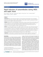
Figure 8 shows the change trend of the total transmis-
sion time E(T) of the traffi c with g interactions between
the MN and CN, where the handoff cycle is a. The
values of g range fro m 100 to 300 and increase in steps
of 50, while the values of a range from 10 to 40 s and
increase in steps of 10 s. In Figure 8, the four planes
from top to bottom indicate E( T)ofMIPv6,HMIPv6,
CNLP and ADA, respectively.
As can be seen from Figure 8, E(T) of ADA is slightly
shorter than that of CNLP and significantly shorter than
that of MIPv6 and HMIPv6. Mor e specifically, the aver-
age total transmission time for ADA is 49.9% shorter
than for MIPv6, 49.0% shorter than for HMIPv6 and
3.3% shorter than for CNLP.
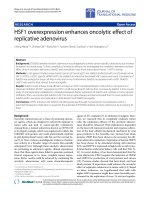
Figure 9 shows the change trend of the total handoff
latency (THL) as a function of g and a. THL indicates
the break-off time of an application caused by handoff
and directly influences user perceived QoS.
As can be seen from Figure 9, the average THL for
ADA is 64.8% shorter than for MIPv6, 49.4% shorter
than for HMIPv6 and 32.1% shorter than for CNLP.
Between the other three protocols, THL for HMIPv6 is
markedly shorter than for MIPv6. When g = 300 and a
= 10 s, THL for HMIPv6 is only 67.2% of that for
MIPv6. THL for CNLP is shorter than that for HMIPv6.
In fact, although the single time handoff latency for
HMIPv6 is shorter than that for CNLP, the total handoff
latency for CNLP is much shorter because its shorter
total transmission time will experience fewer handoffs.
Simulation results
We have transferred the NS2 MobiWan [29] extension
for MIPv6 to ns-2.31 [30] and implemented in it addi-
tional functions such as establishment of bidirectional
tunneling, the return routability procedure, and support
for the retransmission of BUs. We have also complete ly
implemented HMIPv6, CNLP, and ADA in NS2. The
simulation topology is the same as that used for the
numerical analysis in Figure 7. We take four wireless
domains (D
1
-D
4
) and one wired domain (D
5
) to connect
to the backbone. The HA/IRHA is located in D
1
,and
the CMP/ORHA and CN are located in D
5
.
As far as the MAP i s concerned, we have simulated
two extreme cases. In case 1, all wireless domains
belong to one MAP domain, which means that every
handoff is an intra-domain handoff. In case 2, there is
one MAP in each wireless domain and every handoff
will be an inter-domain handoff.
The MN takes a random rectilinear motion without
pause between four wireless domains (D
1
-D
4
) at a speed
of 2 m/s, and comm unicat es with the CN located in D
5
to download data by FTP. Each scenario is simulated for
10000 s and the results are shown in Figures 10, 11, 12
and 13 and Tables 2 and 3.
Figures 10 and 11 show segments of the TCP traces
forMIPv6,HMIPv6,CNLP,andADAduringone
handoff in BT mode and RO mode, respectively. The
x-axis is the time (s) and the y-axisisthenumberof
FTP packets received by the MN in one second. We
choose the segment of 50 s (from 5 s before the hand-
off to 45 s after the handoff) to compare the protocol
performance.
As can be seen from Figure 10, when there is no
handoff, the TCP throughput of ADA and CNLP in BT
mode is close to each other and significantly better than
that of MIPv6 and HMIPv6. When the MN experiences
one handoff, there will be a service disruption in TCP
for all four protocols. However, the TCP throughput of
ADA recovers fastest in these four protocols. During the
15 s after the intra-domain handoff, ADA will on aver-
age receive 3.87, 9.1, and 9.3 more packets every second
than CNLP, HMIPv6, and MIPv6. During the 15 s after
the inter-domai n handoff, ADA and CNLP will on aver-
age receive 5.47 more packets every second than
HMIPv6 and MIPv6. Actually, the intra- domain handoff
latency for HMIPv6 is shorter than for CNLP and for
MIPv6. However, the TCP throughp ut for CNLP is
higher than for HMIPv6 in this case because of its
shorter packet transmission delay in BT mode.
Table 1 Numerical analysis parameters.
Parameters Symbols Values
Handoff cycle a 10-40 s
Inter-domain handoff frequency b 10
Time expectation of handoff detection and CoA configuration r 1300 ms
Transmission delay expectation between one domain to its backbone entry d 150 ms
Transmission delay expectation between any two computers in one domain Δ 10 ms
Transmission delay in backbone between any two domain entries δ 5ms
Expected interactions between MN and CN g 100-300
Liu et al. EURASIP Journal on Wireless Communications and Networking 2011, 2011:25
/>Page 11 of 16
As shown in Figure 11, when there is no handoff, the
TCP throughputs of all four protocols in RO mode are
close to each other. When there is an intra-domain
handoff, the performance of ADA is close to HMIPv6
and better than CNLP and MIPv6. When there is an
inter-domain handoff, the performance of ADA is close
to CNLP and better than HMIPv6 and MIPv6.
In order to make further investigation to the data
interaction process during handoff, we calculate the
transmission delay (TD) of every packet in TCP-sink
and show the results in Fig ures 12 and 13. The x-axis is
the receiving time (s) of the packet and the y -axisisthe
transmission delay of the packet (ms).
As can be seen from Figures 12 and 13, t here are
obvious assembly effects in packe t transmission delay.
For example, the TD for ADA in BT mode is general ly
406 ms. However, a fter handoff, there will be some
packets with TD of 413 or 415 ms. If we follow the
trace of one packet, we will find that this phenomenon
occurs because the TCP-source may send two packets
simultaneously and this results in queuing in the trans-
mission link. In this case, the following packet will arrive
about 7 or 9 ms later than the previous one.
In Figure 12, we compare the packet transmission
delay for CNLP and ADA in BT mode. Performance of
HMIPv6 and MIPv6 in BT mode is significantly worse
than that of these two protocols and is therefore
omittedinthiscase.AsshowninFigure12,TDof
ADA and CNLP in BT mode is only about 406 ms
when there is no handoff. After the handoff, there will
be some packets experiencing higher transmission delay.
As far as the break-off time of TCP is concerned, ADA
breaks 2.54 s in intra-domain handoff and 5.88 s in
inter-domain handoff; while CNLP breaks 5.89 s for
both types of handoffs. As a result, ADA will recover
faster from intra-domain handoff than CNLP.
As shown in Figure 13, the packe t transmission delay
for CNLP and ADA in RO mode is shorter than in BT
mode. During intra-domain handoff, the break-off t ime
forADAandHMIPv6isshort,about2.42and2.53s,
respectively; while the break-off time of CNLP in this
case is about 5.60 s. During inter-domain handoff, the
break-off time for ADA and CNLP is about 5.62 and
5.60 s, respectively; while the break-off time of HMIPv6
in this case is about 6.89 s. As a result, there is a service
interruption in HMIPv6 and the MN needs to reset its
TCP connection instead of making fast retransmission
as in other protocols. During the interruption in
HMIPv6, only three packets are forwarded by the HA
with a transmission delay of 1413 ms.
In Tables 2 and 3, the average TCP throughput, aver-
age packet transmission delay, and average handoff
latency are calculated for MIPv6, HMIPv6, CNLP, and
ADA. In addition, the number of signaling packets for
one handoff has also been calculated to compare the
average handoff cost of these four protocols.
As shown in Tables 2 and 3, the signaling cost of
ADA will be relatively higher than the other three pro-
tocols. As shown in Table 2, in BT mode, ADA
increases by 2 to 4 packets the signaling cost for one
handoff compared to MIPv6 and CNLP. However, ADA
will achieve 418% higher TCP throughput, 70.7% shorter
transmission delay, and 96.6% shorter handoff latency
than MIPv6 in intra-domain handoff. It also can achieve
3.8% higher TCP throughput and 93.2% shorter handoff
Figure 8 Total transmission time of MIPv6, HMIPv6, CNLP, and
ADA in BT mode as a function of g and a.
Figure 9 Total handoff latency of MIPv6, HMIPv6, CNLP, and
ADA in BT mode as a function of g and a.
Liu et al. EURASIP Journal on Wireless Communications and Networking 2011, 2011:25
/>Page 12 of 16
latency than CNLP in this case. When compared with
HMIPv6, although ADA increases the signaling cost by
two packets, it will achieve 275% higher TCP through-
put, 71.1% shorter transmission delay, and 1.8% shorter
handoff latency in intra-domain handoff; 636% higher
TCP throughput, 71.1% shorter transmission delay, and
53.0% shorter handoff latency in inter-domain handoff.
Actually, the total signaling cost of ADA in the entire
NS2 simul atio n is only 6.25 to 9.38 kB for 200 handoffs
in BT mode and 15.6 to 18.8 kB for 200 handoffs in RO
mode. Such small signaling traffic can be ignored in
most network environments.
What should be noted is that in the NS2 simulation
topology, there is only one CMP/ORHA. In fact, the sig-
naling cost of ADA and CNLP will increase as the num-
ber of CMP/ORHA increases. However, t he number of
CNs that are communicating with one MN at the same
time and whose applications all need mobile IP support
is very limited. Thus, the number of CMP/ORHA that
an MN ho lds simul taneously is small. Since these
CMPs/ORHAs are located in different network domains,
the signaling packets will be sent to different destina-
tions, thereby further reducing the possibility of conges-
tion. More research will be conducted to implement
further system simplicity in the real system deployment.
Conclusions
In this article, we have proposed ADA, a distributed
mobile IP-compatible mobility management architec-
ture. In ADA, there are two asymmetric mobility agents
to serve each end-to-end communication. One mobility
agent is located close to the MN and the other is
located close to the CN. We apply ADA to MIPv 6 com-
munications and present the detailed protocol design.
ADA can significantly reduce handoff latency and pro-
vide an eff icient route for all CNs i ncluding those that
do not support route optimization. It also eliminates
congestion at the MN’s HA and home l ink, and reduces
the impact of any possible failures of the HA and home
link on the path to or from the MN. In addition, it
DE
Figure 10 TCP traces for MIPv6, HMIPv6, CNLP, and ADA in BT mode. (a) Intra-domain handoff; (b) inter-domain handoff.
(a) (b)
Figure 11 TCP traces for MIPv6, HMIPv6, CNLP, and ADA in RO mode. (a) Intra-domain handoff; (b) inter-domain handoff.
Liu et al. EURASIP Journal on Wireless Communications and Networking 2011, 2011:25
/>Page 13 of 16
prov ides an easy-to-use mechanism for MNs to manage
and control each traffic session with a different policy
based on practical requirements. Generally, sessions that
need to be maintained during the MN’ s mobility are
mainly client-server types where CNs act as servers.
ADA is well -suited for this case and can help such CNs
enhance their support for their clients’ mobility without
anychangetotheCN’ s implementation. It is a lso con-
venient for the CN-located network to monitor and
control in-bound and out-bound traffic and provide spe-
cific QoS support. ADA does not require modifications
at CNs and HAs, but only moderate modifications at
MNs. It is also backward compatible with Mobile IP
and can be incrementally deployed. Numerical and
sim ulation results both indicate that ADA achieves bet-
ter performance than MIPv6, HMIPv6 and CNLP.
Appendix A
The relevant deductions for obtaining Equation 3 are
given below. The relevant deductions for Equations 6,
17, and 20 can be obtained in an analogous way.
Assume the interaction number for a given application
is g. Thus the transmission time of the data packets for
MIPv6 in BT mode should be
γ · E
BT
MIP
v6
(D
)
. Based on
the definition of a,therewillbe
γ · E
BT
MIP
v6
(D)/
α
of
handoffs during this period. As a result, the total
(a) (b) (c)
Figure 12 Packet transmission delay for CNLP and ADA in BT mode. (a) CNLP; (b) ADA-Intra; (c) ADA-Inter.
DEF
GH
I
Figure 13 Packet transmission delay for HMIPv6, CNLP, and ADA in RO mode. (a) HMIPv6-Intra; (b) CNLP-Intra; (c) ADA-Intra; (d) HMIPv6-
Inter; (e) CNLP-Inter; (f) ADA-Inter.
Liu et al. EURASIP Journal on Wireless Communications and Networking 2011, 2011:25
/>Page 14 of 16
transmission time of this traffic for MIPv6 will be
increased by
(γ · E
BT
MIP
v6
(D)/α) · E
BT
MIP
v6
(L
)
.Ofcourse,
during the increased time, we also need to consider the
increased handoff and the new time cost brought by the
increased handoff. This is given by a standard infinite
geometric series and its sum should be:
E
BT
MIPv6
(T)=γ · E
BT
MIPv6
(D)+γ · E
BT
MIPv6
(D)
E
BT
MIPv6
(L)
α
+ γ · E
BT
MIPv6
(D)
E
BT
MIPv6
(L)
α
2
+
The common ratio in this infinite geometric series is
q =
E
BT
MIPv6
(L)
α
<
1
.Thusfromthefinitesumformulae,
we can get Equation 3:
E
BT
MIPv6
(T)=
γ · E
BT
MIPv6
(D)
1 −
E
BT
MIPv6
(L)
α
=
α · γ (8d +8Δ +4δ)
α − 4d − 4Δ − 2δ − ρ
(3A)
Appendix B
The relevant deductions for obtain ing Equation 10 are
given below. The relevant deductions for Equations 14,
24, and 28 can be obtained in an analogous way.
Based on the deduction i n Appendix A, the total
transmission time expectation of the traffic with g inter-
actions for HMIPv6 in BT mode is also the sum of infi-
nite geometric series:
E
BT
HMIPv6
(T)=γ · E
BT
HMIPv6
(D)
+ γ · E
BT
HMIPv6
(D)
E
BT
HMIPv6
(L)
α
+ γ · E
BT
HMIPv6
(D)
E
BT
HMIPv6
(L)
α
2
+
.
(B1)
The key problem is how to obtain the common ratio
in this infinite geometric series.
Based on the definition of b, the expectation of hand-
off latency for HMIPv6 in BT mode can be given by:
E
BT
HMIPv6
(L)=
E
BT - INTER
HMIPv6
(L)+β · E
BT - INTRA
HMIPv6
(L)
β
+1
(B2)
Based on (B.2), (B.1) can be expressed as:
E
BT
HMIPv6
(T)
=
γ · E
BT
HMIPv6
(D)
1 −
E
BT - INTER
HMIPv6
(L)+β · E
BT - INTRA
HMIPv6
(L)
α(β +1)
=
α · γ (β + 1)(8d +10Δ +4δ)
α
β
+ α − 2
β
Δ −
β
ρ − 4d − 8Δ − 2δ − ρ
(10A)
List of abbreviations
ADA: asymmetric double-agents; BT: bidirectional tunneling; BU: binding
update; CMP: correspondent mobile proxy; CNs: correspondent nodes; CoA:
care-of address; CoT: care-of test; CoTI: care-of test init; DHoA: distributed
home address; FA: foreign agent; GFA: gateway foreign agent; HA: home
agent; HoA_IR: home address for IP reachability; HoA_OR: home address for
optimized routing; HoTI: home test init; HoT: home test; IRHA: reachability
home agent; LCoA: on-link care-of address; LMP: local mobile proxy; MN:
mobile node; MIPv4: mobile IPv4; MAP: mobility anchor point; NGWN: next-
generation wireless networks; NAR: new access router; ORHA: optimized
routing home agent; PAR: previous access router; RCoA: regional care-of
address; RO: route optimization; RTTs: round-trip times; RR: return routability;
TD: transmission delay; TA: temporary home agent.
Acknowledgements
This work has been supported by the National Basic Research Program of
China (No. 2011CB302702), the National Natural Science Foundation of China
(No. 60803140, No. 60970133, No. 61070187, and No. 61003225) and the
Beijing Nova Program.
Author details
1
Institute of Computing Technology, Chinese Academy of Sciences, Beijing,
100190, People’s Republic of China
2
Collaborative Computing Lab, Lenovo
Corporate Research & Development, Beijing, 100085, People’s Republic of
China
3
Department of Electronic Engineering, Macquarie University, Sydney,
Table 2 The ns2 simulation results of MIPv6, HMIPv6,
CNLP and ADA in BT mode.
Type TCP
throughput
(kbps)
Transmission
delay of 1 pkt
(ms)
Handoff
latency
(ms)
Handoff
cost (pkt)
MIPv6 45.4 1389 1621 2
HMIPv6-
Intra
62.6 1408 56 2
HMIPv6-
Inter
30.8 1409 1705 4
CNLP 226.5 407 809 2
ADA-
Intra
235.0 407 55 4
ADA-
Inter
226.8 407 801 6
Table 3 The ns2 simulation results of MIPv6, HMIPv6,
CNLP and ADA in RO mode.
Type TCP
throughput
(kbps)
Transmission
delay of 1 pkt
(ms)
Handoff
latency
(ms)
Handoff
cost (pkt)
MIPv6 187.5 394 1621 8
HMIPv6-
Intra
237.2 407 57 8
HMIPv6-
Inter
176.2 414 1705 10
CNLP 239.3 387 797 8
ADA-
Intra
249.6 387 51 10
ADA-
Inter
239.5 387 798 12
Liu et al. EURASIP Journal on Wireless Communications and Networking 2011, 2011:25
/>Page 15 of 16
NSW, 2109, Australia
4
Graduate University of the Chinese Academy of
Sciences, Beijing, 100049, People’s Republic of China
Competing interests
The authors declare that they have no competing interests.
Received: 14 January 2011 Accepted: 30 June 2011
Published: 30 June 2011
References
1. C Makaya, S Pierre, An analytical framework for performance evaluation of
IPv6-based mobility management protocols. IEEE Trans. Wireless Commun.
7(3), 972–983 (2008)
2. AH Zahran, B Liang, A Saleh, Signal threshold adaptation for vertical
handoff in heterogeneous wireless networks. Mobile Netw. Appl. 11,
625–640 (2006)
3. E Fogelstroem, A Jonsson, C Perkins, Mobile IPv4 regional registration.
Internet Engineering Task Force, RFC 4857, Jun. 2007
4. A Valko, Cellular IP: a new approach to internet host mobility. ACM
SIGMOBILE Computer Comm. Rev. 29(1), 50–65 (1999)
5. A Misra, S Das, A Dutta, A McAuley, S Das, IDMP-based fast handoffs and
paging in IP-based 4G mobile networks. IEEE Commun. Mag. 40(3), 138–145
(2002)
6. R Ramjee, K Varadhan, L Salgarelli, SR Thuel, SY Wand, T La-Porta, HAWAII: a
domain-based approach for supporting mobility in wide-area wireless
networks. IEEE/ACM Trans. Netw. 10(3), 396–410 (2002)
7. J Xie, IF Akyildiz, A distributed dynamic regional location management
scheme for mobile IP. in Proceedings of IEEE INFOCOM 2002, pp. 1069–1078,
June 2002
8. WC Ma, YG Fang, Dynamic hierarchical mobility management strategy for
mobile IP networks. IEEE J. Selected Areas Commun. 22(4), 664–676 (2004)
9. CE Perkins, DB Johnson, Route optimization in mobile IP. Internet Draft
(Work in Progress), Internet Engineering Task Force, draft-ietf-
mobileipoptim-11.txt., Sept. 2001
10. D Johnson, C Perkins, J Arkko, Mobility support in IPv6. Internet Engineering
Task Force, RFC 3775, June 2004
11. C Perkins, IP mobility support for IPv4. Internet Engineering Task Force, RFC
3220, Jan. 2002
12. H Soliman, C Castelluccia, K ElMalki, L Bellier, Hierarchical mobile IPv6
(HMIPv6) mobility management. Internet Engineering Task Force, RFC 5380,
Oct. 2008
13. K Weniger, MIPv6 correspondent node-targeted location privacy and
optimized routing. Internet Draft (Work in Progress), Internet Engineering
Task Force, draft-weniger-mobopts-mip6-cnlocpriv-03., Nov. 2008
14. IF Akyildiz, J Xie, S Mohanty, A survey on mobility management in next
generation all-IP based wireless systems. IEEE Wireless Commun. 11(4),
16–28 (2004)
15. N Kara, Mobility management approaches for mobile IP networks:
performance comparison and use recommendations. IEEE Trans Mobile
Comput. 8(10), 1312–1325 (2009)
16. J Cao, L Zhang, H Chan, SK Das, Design and performance evaluation of an
improved mobile IP protocol. in Proceedings of IEEE INFOCOM 2004, pp.
319–329, Mar. 2004
17. R Koodli, Mobile IPv6 fast handovers. Internet Engineering Task Force, RFC
5268, June 2008.
18. YJ Lee, IF Akyildiz, A new scheme for reducing link and signaling costs in
mobile IP. IEEE Trans Comput. 52(6), 706–711 (2003)
19. R Zheng, Y Ge, JC Hou, SR Thuel, A case for mobility support with
temporary home agents. ACM SIGMOBILE Mob Comput Commun Rev. 6(1),
32–46 (2002)
20. Y Mao, B Knutsson, HH Lu, JM Smith, DHARMA: distributed home agent for
robust mobile access. in Proceedings of IEEE INFOCOM 2005, pp. 1196–1206,
Mar. 2005
21. X P’erez-Costa, M Torrent-Moreno, H Hartenstein, A performance
comparison of mobile IPv6, hierarchical mobile IPv6, fast handovers for
mobile IPv6 and their combination. ACM SIGMOBILE Mob Comput
Commun Rev. 7(4), 5–19 (2003)
22. Y Gwon, J Kempf, A Yegin, Scalability and robustness analysis of mobile
IPv6, fast mobile IPv6, hierarchical mobile IPv6, and hybrid IPv6 mobility
protocols using a large-scale simulation. in Proceedings of IEEE ICC 2004, pp.
7, 4087–4091, June 2004
23. X P’erez-Costa, R Schmitz, H Hartenstein, M Leibsch, A MIPv6, FMIPv6 and
HMIPv6 handover latency study: analytical approach. IST Mobile Wireless
Commun Summit. 100–105 (2002)
24. C Castelluccia, HMIPv6: a hierarchical mobile IPv6 proposal. ACM SIGMOBILE
Mob. Comput Commun. Rev. 4(1), 48–59 (2000)
25. S Pack, Y Choi, Performance analysis of fast handover in mobile IPv6
networks. IFIP Pers Wireless Commun. LNCS 2775, 679–691 (2003)
26. S Pack, Y Choi, A study on performance of hierarchical mobile IPv6 in IP-
based cellular networks. IEICE Trans Commun. E87-B(3), 462–469 (2004)
27. HY Jung, EA Kim, JW Yi, HH Lee, A scheme for supporting fast handover in
hierarchical mobile IPv6 networks. ETRI J. 27(6), 798–801 (2005)
28. G Giaretta, J Kempf, V Devarapalli, Mobile IPv6 bootstrapping in split
scenario. Internet Engineering Task Force, RFC 5026, Oct. 2007
29. MobiWan: NS-2 extensions to study mobility in Wide-Area IPv6 Networks.
/>30. The Network Simulator - ns-2, />doi:10.1186/1687-1499-2011-25
Cite this article as: Liu et al.: Low latency IP mobility management:
protocol and analysis. EURASIP Journal on Wireless Communications and
Networking 2011 2011:25.
Submit your manuscript to a
journal and benefi t from:
7 Convenient online submission
7 Rigorous peer review
7 Immediate publication on acceptance
7 Open access: articles freely available online
7 High visibility within the fi eld
7 Retaining the copyright to your article
Submit your next manuscript at 7 springeropen.com
Liu et al. EURASIP Journal on Wireless Communications and Networking 2011, 2011:25
/>Page 16 of 16