báo cáo hóa học: " Bit-depth scalable video coding with new interlayer prediction" docx
Bạn đang xem bản rút gọn của tài liệu. Xem và tải ngay bản đầy đủ của tài liệu tại đây (932.28 KB, 19 trang )
RESEARC H Open Access
Bit-depth scalable video coding with new inter-
layer prediction
Jui-Chiu Chiang
*
, Wan-Ting Kuo and Po-Han Kao
Abstract
The rapid advances in the capture and display of high-dynamic range (HDR) image/video content make it
imperative to develop efficient compression techniques to deal with the huge amounts of HDR data. Since HDR
device is not yet popular for the moment, the compatibility problems should be considered when rendering HDR
content on conventional display devices. To this end, in this study, we propose three H.264/AVC-based bit-depth
scalable video-coding schemes, called the LH scheme (low bit-depth to high bit-depth), the HL scheme (high bit-
depth to low bit-depth), and the combined LH-HL scheme, respectively. The schemes efficiently exploit the high
correlation between the high and the low bit-depth layers on the macroblock (MB) level. Experimental results
demonstrate that the HL scheme outperforms the other two schemes in some scenarios. Moreover, it achieves up
to 7 dB improvement over the simulcast approach when the high and low bit-depth representations are 12 bits
and 8 bits, respectively.
Keywords: scalable video coding, bit-depth, high-dynamic range, inter-layer prediction
1. Introduction
The need to transmit digital video/audio content over
wired/wireless channels has increased with the continu-
ing development of multimedia processing techniques
and the wide deployment of Internet services. In a het-
erogeneous network, users try to access the same multi-
media resource through different communication links;
consequently, in a compressed bitstream, scalability has
to be ensured to provide adaptability to various channel
characteristics.
To make transmission over heterogeneous networks
more flexible, t he concept of scalable video coding
(SVC) was proposed in [1-3]. Currently, SVC has
become an extension of the H.264/AVC [4] video-cod-
ing standard so that full spatial, temporal, and quality
scalability can be realized. Thus, any reasonable extrac-
tion from a scalable bitstream will yield a sequence with
degraded characteristics, such as smaller spatial resolu-
tion, lower frame rate, or reduced visual quality.
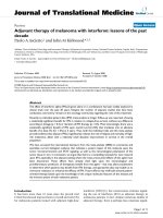
Figure 1 shows the coding architecture of the SVC
standard with two-layer spatial and quality scalabilities.
A low-resolution input video can be generated from a
high-resolution video by spatial downsampling and
encoded by the H.264/AVC standard to form the base
layer. Then, a quality-refined version of the low-resolu-
tion video can be obtained by combining the base layer
with the enhancement layer. The enhancement layer can
be realized by coarse grain scalability (CGS) or medium
grain scalability (MGS). Similar to the H.264/AVC
encoding procedure, for every MB of the cu rrent frame,
only the residual related to its prediction will be
encoded in SVC.
The H.264/AVC standard supports two kinds of pre-
diction: (1) intra-prediction, which removes spatial
redundancy within a f rame; and (2) inter-prediction,
which eliminates temporal redundancy among frames.
With regard to spatial scalability in SVC, in addition to
intra/inter-predictions, theredundancybetweenthe
lower and the higher spatial layers can be exploited and
removed by different types of inter-layer prediction, e.g.,
inter-layer intra-prediction, inter-layer motion predic-
tion, and inter-layer residual prediction. Hence, the cod-
ing efficiency of SVC will be better than that under
simulcast conditions, where each layer is encoded inde-
pen dently, since inter-layer prediction between the base
and the enhancement layers may yield a better rate-dis-
tortion (R-D) performance for some MBs.
* Correspondence:
Department of Electrical Engineering, National Chung Cheng University,
Chia-Yi, 621, Taiwan
Chiang et al. EURASIP Journal on Advances in Signal Processing 2011, 2011:23
/>© 2011 Chiang et al; licensee Springer. This is an Open Access article distributed under the terms of the Creative Commons Attribution
License (http://creativecommons. org/licenses/by/2.0), wh ich permits unrestricted use, distribution, and repr oduction in any medium,
provided the original work is properly cited.
Acquiring high-dynamic range (HDR) images has
become easier with the development of new capture
techniques. As a result, HDR images receive consider-
able attention in many practical applications [5,6]. For
example, in High-Definition Multimedia Interface 1.3,
the supported bit-depth has been extended from 8 to 16
bits per channel, so that v iewers perceive the displayed
content as more r ealistic. In 2003, the j oint video team
(JVT) called for proposals to enhance the bit-depth
scope of H.264/AVC video coding [7]. The supported
bit-depth in H.264/AVC is now up to 14 bits per color
channel. However, the bandwid th required to transmit
the encoded high bit-depth image/video content is
much larger. In addition, conventional display devices
cannot present the HDR video format, and so it is
necessary to design algorithms that can resolve such
problems. In addition to the three supported scalabil-
ities, it is possible to extend the technical feasibility of
the SVC standard to provide the bit-depth scalability.
The embedded scalable bitstream can be truncated
according to the bit-depth requirements of the specific
application. In contrast, a high-quality, high bit-depth
and high-resolution output is achievable by decoding
thecompletebitstreamforhigh-definition television
(HDTV) applications.
To cope with the increased size of high bit-depth
image/video data compared to those of conventional
LDR applications, it i s necessary to develop appropriate
compression techniques. Some approaches for HDR
image compression that concentrate on backward com-
patibility with conventional image standards can be
found in [8,9]. M oreover, to address the scalability issu e,
a number of bit-depth scalable video-coding algorithms
have been proposed in recent years, and many bit-depth-
related proposals have been submitted to JVT meetings
[10-14]. Similar to spatial scalability, the concept of inter-
layer prediction is applied in bit-depth scalability to
exploit the high correlation between bit-depth layers. For
example, an inter-layer prediction scheme realized as an
inverse tone-mapping technique was proposed in [10].
The scheme predi cts a high bit-depth pixel from the cor-
responding low bit-depth pixel through scaling plus off-
set, where the scale and offset values are estimated from
spatial neighboring blocks. Segall [15] introduced a bit-
depth scalable video-coding algorithm that is applied on
the macroblock (MB) level. In this scheme, the base layer
isalsogeneratedbytonemappingofthehighbit-depth
input and then encoded by H.264/AVC. For high bit-
depth input, in addition to int er/intra-predict ion, inter-
layer prediction is exploited to remove redundancy
between bit-depth layers where a prediction from the low
bit-depth layer is generated using a gain parameter and
an offset p aramete r. Moreover, the high and the low bit-
depth layers use the same motion information estimated
in the low bit-depth layer. In [11,16], Winken et al. pro-
posed a coding method that first converts a high bit-
depth video sequence into a low bit-dep th format, which
is then encoded by H.264/AVC as the base layer. Next,
the reconstructed base layer is processed inversely as a
prediction mechanism to predict the high bit-depth layer.
The difference between the original high bit-depth layer
and the predicted layer is treated as an enhancement
layer, and no inter/intra-prediction is performed for the
high bit-depth layer. In [17,18], those authors proposed
an implementation that considers spatial and bit-depth
scalabilities simultaneously. To improve the coding
Figure 1 The SVC coding architecture with two spatial layers [3].
Chiang et al. EURASIP Journal on Advances in Signal Processing 2011, 2011:23
/>Page 2 of 19
efficiency , Wu et al . [17] recommended that inverse tone
mapping should be realized before spatial upsampling.
Moreover, the residual of the low bit-depth layer should
be upsampled and utilized to predict the residual of the
high bit-depth layer [18]. This approach removes more
redundancy than the methods in [15,16]. In [19], an
MPEG-based HDR video-coding scheme was proposed.
First, the low dynamic range (LDR) frames, which are
tone-mapped versions of the HDR frames, are encoded
by MPEG and serve as references for the HDR frames by
appropriate processing. The residuals associated with the
original HDR frames are filtered to eliminate invisible
noise before quantization and entropy encoding. Finally,
the encoded residual is stored in the auxiliary portion of
the MPEG bitstream.
Most bit-depth scalable coding schemes use low bit-
depth information to predict high bit-depth information.
In addition to the inter-layer prediction from the low
bit-depth layer, we consider also to perform the inter-
layer prediction in the reverse direction in this article, i.
e., from the high bit-depth layer to the low bit-depth
layer [20]. The rationale for our approach is that the
information contained in the high bit-depth la yer should
be more accurate than that in the low bit-depth layer.
Thus, better coding efficiency can be expected when
reverse prediction is adopted. Our previous study [20]
can be seen as a preliminary and partial result of this
study. A more detail ed description of the proposed
schemes, as well as a more complete and rigorous per-
formance analysis of the proposed schemes will be
addressed in this article.
The rema inder of this article is organized as follows.
Section 2 reviews the construction of HDR images and
their properties, as well as several tone- and i nverse
tone-mapping methods. In Section 3, we introduce t he
proposed LH scheme, which is similar to most current
methods. We also describe the proposed HL scheme
and the combined LH-HL scheme in detail. Section 4
details the experimental results. Then, in Section 5, we
summarize our conclusions.
2. HDR images and tone-mapping technology
HDR technologies for the capture and display of images/
video content have grown rapidly in recent years. As a
result, HDR imaging has become increasingly important
in many applications, especially in the entertainment
field, e.g., HDTV, digital c inema, mixed reality r ender-
ing, image/video editing, and remote sensing. In this
section, w e introduce the concept of HDR image tech-
nology and some tone/inverse tone-mapping techniques.
2.1. HDR images
In the real world, the dynamic range of light perceived
by humans can be 14 orders of magnitude [21]. Even
with in the same scene, t he ratio of the brightest inten-
sity over the darkest inten sity perceived by humans is
about five orders of magnitude. However, the dynamic
range s upported by contemporary cameras and display
devices is much lower, which explains the visual quality
of images containing natural s cenes being not a lways
satisfactory.
There are two kinds of HDR images: images rendered
by computer graphics and images of real scenes . In this
article, we focus on the latter type, which can be cap-
tured directly. Such la tter type sensors for capturing the
HDR image have been developed in recent years, and
associated products are now available on the market.
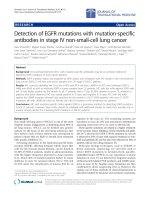
HDR images can also be constructed by conventional
cameras using several LDR images with varied exposure
times [22], as shown in Figure 2. A number of formats
can be used to store HDR images, e.g., Radiance RGBE
[23], LogLuv TIFF [24], and OpenEXR [25]. Currently,
the conventional display and printing devices do n ot
support HDR format, and it is difficult to render such
images on these devices. Tone-mapping techniques have
been developed to address the problem. We discuss sev-
eral of those techniques in this article.
2.2. Tone mapping
Bit truncation is the most intuitive way to transform
HDR images into LDR images, but it often results in
serious quality degradation. Thus, the key issue
addr essed by tone-mapping techniques is how to gener-
ate LDR images with smooth color transiti ons in conse-
cutive areas while maintaining the details of the original
HDR images as much as possible. Tone-mapping techni-
ques can be categorized into four different types,
namely, global operations, local operations, frequency
domain operations, and gradient domain operations
[21]. Global methods produce LDR images according to
some predefined tables or functions based on the HDR
images’ features, but the methods also generate artifacts.
The most significant artifacts result from distortion of
the detail o f the brightest or the darkest a rea. Although
such artifacts can be resolved by using a local operator,
local methods are less popular than global methods due
to their high complexity. In contrast, f requency domain
opera tions emphasize compression of the low-frequency
content in an image, while gradient domain techniques
try to attenuate the pixel intensity of areas with a high
spatial gradient. Next, we introduce the tone-mapping
algorithm used in our proposed bit-depth scalable cod-
ing schemes.
2.2.1. Review of the tone-mapping algorithm presented in
[26]
Thezonesystem[27]allowsaphotographertouse
scene measurements to create more realistic photos. We
adopt this concept in the tone-mapping technique
Chiang et al. EURASIP Journal on Advances in Signal Processing 2011, 2011:23
/>Page 3 of 19
employed in the proposed bit-depth scalable coding
schemes. Usually, photographers use the zone system to
map a real scene with a HDR into print zones. In the
first step, it is necessary to determine the key of the
scene, which indicat es whether the scene is bright, nor-
mal, or dark. For example, a room that is painted white
would have a high key, while a dim room would have a
low key. The key can be estimated by calculating the
log-average luminance [28] as follows:
¯
L
HDR
= exp
⎛
⎝
1
M
x,y
log
δ + L
HDR
(x, y)
⎞
⎠
,
(1)
where L
HDR
(x, y) is the HDR luminance at position (x,
y); δis a small value to avoid singularity in the log com-
putation; and M is the total number of pixels in the
image. Then, a scaled luminance value L
s
( x, y)canbe
computed as follows:
L
s
(x, y)=
c
¯
L
HDR
L
HDR
(x, y)
,
(2)
where c is a constant value determined by the user. For
scenes with a normal key, c i s usually se t at 0.1 8 because
¯
L
HDR
is mapped to the middle-gray area of the print
zone, and it corresponds to 18% reflectance of the print.
After that, a normalized LDR image can be obtained
by
L
LDR
(x, y)=
L
s
(x, y)
1+L
s
(x, y)
1+
L
s
(x, y)
L
2
white
,
(3)
where L
White
represents the smallest luminance
mapped to pure white, and the value of L
LDR
(x, y)is
between 0 and 1. The first component on the right-
hand side of (3) t ries to compress areas of high lumi-
nance. Thus, areas with low luminance are scaled line-
arly, while areas of high luminance are compressed to a
larger sc ale. The second component on the right-hand
side of the equation is for linear scaling after consider-
ing the normalized maximum-intensity of the HDR
image. For further details, readers may refer to [26].
Then, the final LDR image can be generated by mapping
L
LDR
(x, y) into the corresponding value within the LDR.
For example, the final LDR image
L
F
LDR
(x, y
)
can be
easily obtained by
L
F
LDR
(x, y) = round
L
LDR
(x, y) ×
2
N
L
− 1
,
(4)
where N
L
denotes the bit-depth of the LDR image.
2.3. Inverse tone mapping
In general, HDR images cannot be recovered completely
after inverse tone mapping of tone-mapped LDR images.
This is because inverse tone mapping is not an exact
inverse of tone mapping in the mathematical sense.
Consequently, the goal of inverse tone mapping is to
minimize the distortion of the reconstr ucted HDR
images after the inverse-mapping process. In [11,16],
those authors propose three simple and intuitive meth-
ods for inverse tone mapping, namely, linear scaling, lin-
ear interpolation, and lo ok-up table mapping. The look-
up table is compiled by minimizing the difference
between the original HDR images and the images after
tone mapping followed by inverse tone mapping. In
addition, some inverse tone-mapping techniques based
on scaling and offset are described in [10,15]. Specifi-
cally, HDR images are predicted by the addition of
Synthesize
Tone mapping
HDR Image
LDR image
Figure 2 The generation of HDR images from multiple LDR images [22].
Chiang et al. EURASIP Journal on Advances in Signal Processing 2011, 2011:23
/>Page 4 of 19
scaled LDR images with a suitable offset. In [29], an
invertible tone/inverse tone-mapping pair is proposed.
The associated tone-mapping algorithm i s based on the
μ-Law encoding algorithm [30], and its mathematical
inverse form can be derived. However, because of the
quantizatio n error generated in the encoding process, it
is impossible to reconstruct HDR images perfectly. In
this study, we adopt the look-up table-mapping process
proposed in [11,16] for inverse tone mapping.
3. Proposed methods
3.1. The LH scheme
To ensure that the generated bitstream is embedded and
be compliant with the H.264/AVC standard, most bit-
depth scalable coding schemes employ inter-layer pre-
diction, which uses the low bit-depth layer to predict
the high bit-depth layer [15-18]. The proposed LH (low
bit-depth to high bit-depth) scheme adopts this idea
with several modifications. We explain how it differs
from other methods later in the article.
The coding structure of the proposed LH scheme is
shown in Figure 3. The low bit-depth input is obtained
after tone mapping of the original high bit-depth input
and then encoded by H.264/AVC, as shown in the left-
hand side of Figure 3. In this way, the generated bit-
depth scalable bitstream allows for backward compatibil-
ity with H.264/AVC.
The right-hand side of Figure 3 shows the coding pro-
cedures for the high bit-depth layer. Like the low bit-
depth layer, the encoding process is implemented on the
MB level, but there are two differences. First, in addition
to intra/inter-predictions, the high bit-depth MB level
gets another prediction from the corresponding low bit-
depth MB by inverse tone mapping of the reconstructed
low bit-depth MB. This prediction, which we call intra-
prediction from low bit-depth (IPLB), can be regarded
as a type of inter-layer prediction and treated as an
additional intra-prediction mode with a blo ck size of 16
× 16, which is similar to inter-layer intra-prediction per-
formed in the spatial scalability of the SVC standard.
Residual Prediction
TM
Inter
Predictio
n
Intra
Prediction
T/Q
Entropy
Coding
MUX
Inter
Prediction
Intra
Prediction
IPLB
ITM
IQ/IT
High bit-depth input
-
-
-
-
Bit-depth scalable bitstream
ITM_R
T/Q
Recon./
Storage
IQ/IT
Residual Prediction
Recon./
Storage
Entropy
Coding
Figure 3 The coding architecture of the proposed LH scheme.
Chiang et al. EURASIP Journal on Advances in Signal Processing 2011, 2011:23
/>Page 5 of 19
Thus, two kinds of intra-prediction are available in the
proposed LH scheme: one explores the spatial redun-
dancy within a frame, while the other tries to remove
the redundancy between different bit-depth layers.
Furthermore, to improve the coding efficiency of
inter-coding, the residual of the low bit-depth MB is
inversely tone mapped and utilized to predict the resi-
dual of the high bit-depth MB. The process, called resi-
dual prediction can be regarded as another kind of
inter-layer prediction and can be realized in two ways.
The high bit-depth MB can perform motion estimation
and motion compensation before subtracting the pre-
dicted residual derived from the low bit-depth layer, or
it can subtract the predicted residual before motion esti-
mation and motion compensation, which is similar to
inter-layer residual prediction realized in the spatial
scalability of the SVC standard. The residual prediction
operation can be mathematically repressed as below:
Residual prediction 1 → MEMC
F
HBD
− ITM
R
ˆ
R
LBD
Residual prediction
2 → MEMC
F
HBD
− ITM R
ˆ
R
LBD
,
(5)
where F
HBD
and
ˆ
R
LBD
denote the high bit-depth layer
MB and t he reconstructed residual of the low bit-depth
layer MB, respectively. MEMC sta nds for the operation
of motion estimation, followed by motion compensation,
while ITM_R for inverse tone mapping of residual. Both
residual prediction methods try to reduce th e amount of
redundancy in residuals of the low and the high bit-
depth layers. Besides, contrary to IPLB mode where the
inverse tone mapping used is based on look-up table,
the inverse tone-mapping method used for the residual
is based on linear scaling and expressed as follows,
ITM R=LBDresidual ×
HBD input/LBD input
,
(6)
where LBD_residual denotes the residual of the low
bit-depth MB; HBD_input and LBD_input stand for the
intensities of high bit-depth pixel and of low bit-depth
pixel, respectively.
Basically, we utilize both IPLB prediction and residual
prediction based on the results of R- D optimization.
Note that there are four kinds of prediction in the pro-
posed LH scheme: intra-prediction, inter-prediction,
IPLB prediction, and residual prediction, which can be
used in two ways. Moreover, residual prediction coop-
erates with inter-prediction if doing so yields better cod-
ing efficiency, while IPLB competes with other types of
prediction. If inter-layer prediction (i.e., IPLB or residual
prediction) is not used, then t he high bit-depth layer is
enco ded by H.264/AVC. In this case, the coding perfor-
mance in such scalable coding scheme is the same as
that achieved by simulcast. Next, we summarize the
features of the proposed LH scheme, which distinguish
it from several current approaches.
1. IPLB: Similar to most bit-depth SVC schemes
[15-18], the high bit-depth MB can be predicted
from the corresponding low bit-depth MB by in verse
tone mapping. However, in [16], intra/inter-predic-
tion is not realized in the high bit-depth layer in
conjunction with inter-layer prediction.
2. Residual Prediction: Residual Prediction can be
applied in two ways, as indicated in Figure 3. The
high bit-depth MB can perform motion estimation
after subtracting the predicted residual derived from
the low bit-depth layer, or it can subtract the pre-
dicted residual after motion compensation. Residual
prediction is not used in the schemes proposed in
[15,16]. The residual prediction operation described
in [17,18] is performed only after motion compensa-
tion in the high bit-depth layer.
3. Motion information: In the proposed LH scheme,
both the low and the high bit-depth layers have their
own motion information including the MB mode
and motion vector (MV). This is contrary to the
approach in [15], where the high bit-depth MB uses
directly the motion information obtained in the cor-
responding low bit-depth MB.
3.1.1. Bitstream structure in the LH scheme
In the LH scheme, the bitstream is embedded; hence, a
reasonable truncation of the bitstream always ensures
successful reconstruction of low bit-depth images. Fig-
ure 4 sho ws a possible arrangemen t of the L H scheme’s
bitstream structure where the GOP (group of pictures)
size is 2. For t he sake of simplicity, P frame contains no
intra-MB in Figures 4, 6, and 7, although intra-MBs are
allowed in P frames depending on the R- D performance.
LBD_I represents the low bit-depth I-frame information;
while LBD_Motion_Info and LBD_P denote, respec-
tively, the motion information and all the associated
data for the low bit-depth P-frame. The bitstream gener-
ated by the LH scheme is backward, compatible with
H.264/AVC and can be extended to include higher bit-
depth information as an e nhancement layer. For exam-
ple, to reconstruct the high bit-depth frames, we can
use the following components: HBD_I, HBD_Motio-
n_Info, and HBD_P, which represent, respectively, the
information needed to reconstruct the high bit-depth I-
frame, related motion information of P-frame, and the
residual needed to reconstruct the P-frame. If the
enhancement layer is not available at the decoder, then
a rough high bit-depth video sequence may be generated
by look-up table mapping. On the other hand, a quality
refined high b it-depth video can be reconstructed if the
enhancement layer is available.
Chiang et al. EURASIP Journal on Advances in Signal Processing 2011, 2011:23
/>Page 6 of 19
3.2. The HL scheme
In this section, we propos e a new scheme called the HL
scheme which processes the high bit-depth layer first,
and then provides the low bit-depth layer with useful
information after suitable processing. The scheme
achieves a b etter R-D performance in some scenarios,
for example, if a display device supports t he high bit-
depth format and the user wants to view only the high
bit-depth video content or the user requests both bit-
depth versions simultaneously. The HL scheme tries to
achieve a good coding performance in such applications.
However, if the user only has a display device with low
bit-depth, then a truncated bitstream would still guaran-
tee successful reconstruction of a low bit-depth video.
First, we consider I-frame encoding in t he proposed
HL scheme. The high bit-depth I-frame is H.264/AVC
encoded directly. It is not necessary to encode and
transmit the corresponding low bit-depth layer, which
can be created by tone mapping of the reconstructed
high bit-depth I-frame at the decoder. Thus, the bit-
stream does not reserve a spe cific space for the low bit-
depth I-frame.
For the P-frame, the low bit-depth layer input is
obtained by tone mapping of the original high bit-depth
GOP GOP
Ξ
GOP GOP GOP
Ξ
GOP
LBD_I LBD_Motion_Info LBD_P HBD_I
Base layer Enhancement layer
HBD_Motion_Info
HBD_P
Figure 4 A possible bitstream structure in the proposed LH scheme.
Residual Prediction
TM ME
MC
MC
Recon./
Stora
g
e
Recon./
Stora
g
e
IQ/IT
T/Q TM_R
IQ/IT
ITM_R
Entropy
Coding
Entropy
Coding
MUX
Bit-depth scalable bitstream
-
-
-
High bit-depth input
T/Q
Figure 5 The coding architecture for inter-MBs in the proposed HL scheme.
Chiang et al. EURASIP Journal on Advances in Signal Processing 2011, 2011:23
/>Page 7 of 19
input. Note that, in the HL scheme, the high bit-depth
layer is processed before the corresponding low bit-
depth layer. Every MB in the high bit-depth layer is
intra-coded or inter-coded, depending on the optimiza-
tion of the R-D cost. If the high bit-depth MB is desig-
nated as intra-mode, then the remaining coding
procedure is exactly the same as that in H.264/AVC.
The associated low bit-depth MB can be obtained at the
decoder after tone mapping of the reconstructed high
bit-depth MB using the procedures adopted for I-
frames. On the other hand, if the high bit-depth MB is
designated as inter-mode, then the subsequent coding
procedures are different from those in H.264/AVC
inter-coding. Figure 5 illustrates the encoding architec-
ture for the inter-MB in the HL scheme. The encoding
process can be summarized by three steps:
Step 1: After perf orming motion est imation (ME) and
deciding the mode for the high bit-depth MB, the
derived motion information, which contains the MV
and MB modes of the high bit-depth MB, is transferred
to the low bit-depth layer and utilized b y the corre-
sponding low bit-depth MB.
Step 2: After performing motion compensation (MC),
the residual of the high bit-depth MB is tone mapped,
followed by discrete cosine transform (DCT), quantiza-
tion, and entropy encoding. Then, it becomes part of
the embedded bitstream of the corresponding low bit-
depth MB. As a result, the decoder can reconstruct the
low bit-depth MB directly using the motion information
of the high bit-depth MB to perform mot ion compensa-
tion, followed by a summation with the decoded
residual.
The tone mapping for the residual is different from
those used in textures. The tone-mapping method
adopted for residual data is based on linea r scaling and
expressed as follows:
LBD residual = TM R
(
HBD residual
)
=HBDresidual ×
(
LBD MC/HBD MC
)
(7)
HDR MC = ITM
(
LBD MC
)
(8)
where TM_R and ITM denote the tone mapping
for residual data and inverse tone mapping for t ex-
tures, respectively. LBD_MC stands for the low b it-
depth pixel intensity after performing motion com-
pensation using the MV derived in the high bit-
depth lay er MB.
Step 3: The reconstructed residual of the low bit-de pth
MB is converted back to the high bit-depth layer by
inverse tone mapping, similar to that performed in the LH
scheme. Then, only the difference between the residual of
the high bit-depth MB and the residual predicted from the
low bit-depth MB is encoded, under wh ich situat ion, a
better R-D performance is achieved in this way.
From the description above, the features of the HL
scheme can be summarized as follows:
GOP GOP
Ξ
GOP GOP GOP
Ξ
GOP
LBD_I HBD_Motion_Info LBD_P HBD_I
Base layer Enhancement layer
HBD_P
Figure 7 A possible bitstream structure in the proposed LH-HL scheme.
GOP GOP
Ξ
GOP GOP GOP
Ξ
GOP
HBD_I HBD_Motion_Info LBD_P HBD_P
Base layer Enhancement layer
Figure 6 A possible bitstream structure in the proposed HL scheme.
Chiang et al. EURASIP Journal on Advances in Signal Processing 2011, 2011:23
/>Page 8 of 19
1. The low bit-depth I-frame is not transmitted and
can be generated at the decoder by tone mapping of
the reconstructed high bit-depth layer I-frame.
2. Two kinds of inter-laye r prediction are employed
for inter-coding in the HL scheme.
a. The first kind of inter-layer predictio n is from
the high bit-depth layer to the low bit-depth
layer, where the motion information derived in
the high bit-depth layer is shared by the low bit-
depth layer. Moreover, the residual of the high
bit-depth layer is tone mapped to be the residual
of the low bit-depth layer.
b. The sec ond kind of inter-layer prediction is
from the low bit-depth layer to the high bit-
depth layer, where the quantized residual o f the
low bit-depth layer can be used for predicting
the residual of the high bit-depth layer. It is
called residual prediction in the HL scheme.
3.2.1. Bitstream structure in the HL scheme
The bitstream in the HL scheme is different fro m that in
the LH scheme, as shown in Figure 6, where the GOP
size is 2. The base layer consists of three components. It
starts by filling up information about the high bit-depth
I-frame, denoted as HBD_I, followed by information
about the P-frame f or both the high bit-depth and low
bit-depth layers. The low bit-depth MB and the corre-
sponding high bit-depth MB are reconstructed using the
same MV and MB modes, denoted as HBD_Motion_Info.
The residual of the high bit-depth layer is tone mapped
to the low bit-depth layer. After transformation, quanti-
zation- and entropy-encoding operations, it will form
LBD_P. HBD_P denotes the residual data used for recon-
structing the high bit-depth layer. Obviously, the entire
encoded HL bitstream is smaller than the bitstream in
the LH scheme because of the absence of low bit-depth
intra-c oded MBs and because both bit-depth layers share
motion information for inter-coded MBs.
Note that, although motion estimation is only per-
formed in the high bit-depth layer, the low bit-depth
layer in the HL schemes uses this motion information,
as well as the residual of the high bit-depth layer for
reconstruction. The motion information is put into the
base layer bitstream, inste ad of into the enhancement
layer bitstream. Moreover, the residual data in the ba se
layer comes from the tone mapping of the residual of
the high bit-depth layer. After transformation, quantiza-
tion and entropy coding, this residual is also put into
the base layer bitstream. Thus, there is no drift issue in
the HL schemes due to the embedded bitstream
structures.
3.3. Combined LH-HL scheme
As mentioned earlier, for I-frames, the bitstream of the
HL scheme only contains high bit-depth information.
Intuitively, this will result in bandwidth inefficiency if
the receiver uses a low bit-depth display device, espe-
cially in the case where a small GOP size is adopted and
the data in the I-frames dominate the bitstream. T o
improve the coding efficiency in such situation s, we
combine the HL scheme with the LH scheme to form a
hybrid LH-HL scheme in which the intra-MBs and
inter-MBs are enco ded by the LH scheme and the HL
scheme, respectively. It means that intra-mode-encoding
path in the LH scheme and inter-mode-encoding path
in the H L scheme are combined in the LH-HL scheme.
For every high bit-depth MB in the LH-HL scheme,
either intra-mode or inter-mode is chosen by comparing
the R-D cost. It means that the R-D cost of intra-coding
by the LH scheme and the R-D cost of inter-coding by
theHLschemewillbecompared.IftheR-D cost of
intra-coding by the LH scheme is smaller, then this MB
is encoded as intra-mode; otherwise, it is inter-mode
and encoded by the HL scheme. The combined LH-HL
scheme t ries to improve the cod ing performance of the
HL scheme in the above situation.
3.3.1. Bitstream structural in the LH-HL scheme
Figure7showsapossiblebitstreamstructureofthe
combined LH-HL sche me, where the GOP size is 2. For
each GOP in the base layer, three components provide
the information used for reconstr ucting t he low bit-
depth layer, i.e., LBD_I for low bit-depth I-frames,
HBD_Motion_Info and LBD_P for the low bit-depth P-
frame. Besides, HBD_I and HBD_P are used to ensure
the reconstruction of the high bit-depth I- and P-frames,
respectively.
Note that, the LH-HL scheme is H.264/AVC compati-
ble. First, intra-MB coding in LH-HL scheme is exactly
the same as that in LH scheme. For inter-MB in P
frame, the MV obtained in the high bit-depth layer MB
is used by the low bit-depth layer directly and put i nto
the base layer b itstream. Moreover, the residual data in
the base layer comes from the tone mapping of the resi-
dual of the high bit-depth layer. After transformation,
quantization, and entropy coding, this residual is also
put into the base la yer bitstream. In this way, the gener-
ated bit-depth scalable bitstream of the LH-HL scheme
allows backward compatibility with H.264/AVC, and
there is no drift issue involved.
3.4. Comparison of three proposed schemes
InTable1,wecomparethecodingstrategiesofthe
three proposed schem es for the low bit-depth layer and
the high bit-depth layer, denoted as LBD and HBD,
respectively. Here, intra-coding and inter-coding opera-
tions are the same as those defined in H.264/AVC; that
is, intra-coding and inter-coding include intra-prediction
and inter-prediction, respectively, followed by DCT,
quantization, and entropy coding. Note that, for the
Chiang et al. EURASIP Journal on Advances in Signal Processing 2011, 2011:23
/>Page 9 of 19
high bit-depth layer, residual prediction in the LH
scheme can be used either before or after motion esti-
mation. On the other hand, in the HL scheme, residual
prediction can only be used after motion estimation and
motion compensation. Moreover, HBD-based inter-co d-
ing requires that the residual of the high bit-depth MB
is tone mapped, followed by DCT, quantization, and
entropy coding before it can become part of the
embedded bitstream of the l ow bit-depth MB; and no
motion estimation is executed in the low bit-d epth
layer. Then, the reconstruction of the low bit-depth
layer is realized by using the MV of the high bit-depth
layer to find the referenced block in the previously
reconstructed low bit-depth frame, in conjunction with
the decoded residual.
Table2summarizestheinter-codingcomplexityof
the proposed three schemes. Compared to [15], the high
bit- depth MB in the LH scheme needs higher computa-
tion complexity due to multi-loop MC, once IPLB mode
is chosen. In the HL and the LH-HL schemes, the low
bit-depth layer needs no motion estimation because a
shared MV is provided by the high bit-depth layer.
Moreover, there i s no multi-loop MC issue in the hig h
bit-depth layer.
4. Experimental results
We extend H.264/AVC basel ine profi le to complete the
proposed bit-depth scalable video-coding scheme. The
used reference software is JM 9.3, which supports 12-bit
videoinput.Toevaluatetheperformanceofthepro-
posed algorithms, two 12-bit (high b it-depth) test
sequences, “Sunrise” (960 × 540) and “ Library” (900 ×
540), provided in [31] are used in the simulation. Both
sequences have low camera motion, and the color
format is 4:2:0. In our systems, the low bit-depth input
is 8 bits for each color channel, a nd the high b it-depth
input is 12 bits. The frame rate of both sequences is 30
Hz, and the 8-bit representa tions are acquire d by tone
mapping of the original 12-bit sequences. We employ
the tone -mapping method in [26] , and use look-up table
mapping [11,16] to realize the inverse tone mapping.
Note that the tone and inverse-tone mapping techniques
used in this article are the same for all the schemes.
Thus, we can avoid the influence of different techniques
on the coding efficiency. Both the high and low bit-
depth layers use the same quantization parameter (QP)
settings, so no extra QP scaling is needed to encode the
high bit-depth layer. Moreover, GOPs containing 1, 4, 8,
and 16 pictures are used for differentiating the coding
efficiency of I-frames and P-frames in proposed coding
schemes.
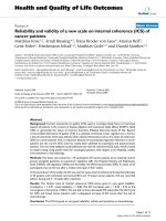
4.1. Intra-coding performance (GOP = 1)
The R-D performance of the proposed algorithm is
shown in Figures 8 and 9 when the GOP s ize i s 1. The
PSNR is calculated as follows:
PSNR = 10log
10
2
N
− 1
2
MSE
,
(9)
where N is the bit-depth, and MSE d enotes the mean
squared error between the reconstructed and the origi-
nal images. The perfor mances of 12-bit single-layer and
simulcast codings are also compared. In this case, the
HL scheme is equi valent to single-layer coding; and the
combined LH-HL scheme is the same as the LH scheme
as well as the approach in [15].
Figures 8 and 9 show that the HL and the LH
schemes achieve better coding efficiency than the simul-
cast scheme. Specifically, the HL scheme achieves up to
7 dB improvement o ver t he simulcast scheme in the
high bit-rate scenario. Table 3 summarizes the percen-
tages of IPLB mode employed in I-frames for the LH
scheme. The table shows that the percentages of IPLB
mode increase, as the QP value decreases. This indicates
that hig h bit-depth intra-MBs are likely to be predicted
from their low bit-dep th versions, ins tead of by conven-
tional intra-prediction, if the corresponding low bit-
Table 1 Comparison of the coding strategies of the proposed schemes
LBD intra-MB LBD inter-MB HBD intra-MB HBD inter-MB
[15] Intra-coding Inter-coding Intra-coding
IPLB
Inter-coding
LH scheme Intra-coding Inter-coding Intra-coding
IPLB
Inter-coding
Residual prediction
HL scheme Not applicable HBD-based inter-coding Intra-coding Inter-coding
Residual prediction
LH-HL scheme Intra-coding HBD-based inter-coding Intra-coding
IPLB
Inter-coding
Residual prediction
Table 2 Comparison of the inter-coding complexity of
the proposed schemes
[15] LH scheme HL scheme LH-HL scheme
LBD ME ME No ME No ME
MC MC MC MC
HBD ME ME ME ME
Single-loop MC Multi-loop MC Single-loop MC Single-loop MC
Chiang et al. EURASIP Journal on Advances in Signal Processing 2011, 2011:23
/>Page 10 of 19
depth MB is reconstructed w ell. As a result, the gener-
ated bitrate can be reduced.
4.2. Coding performance when GOP = 4, 8, and 16
Next, we consider the coding performance of the pro-
posed schemes when GOP is 4, 8, and 16. Figures 10
and 11 compare the performances of the schemes for
sequences “ Sunrise” and “Library, ” respectively. The
results demonstrate that the three proposed schemes
outperform the simulcast scheme. It is also clear that
the HL scheme outperforms the LH scheme, the com-
bined LH-HL scheme, as well as the approach proposed
in [15] by approximate ly 2 dB. Tables 4 and 5 detail the
statistical distributions of the inter-layer mode chosen
for M Bs in the high bit-depth layer in the LH scheme
and the HL scheme, respectively. Note that, for the HL
scheme, only the inter-frame is considered for the statis-
tics in Table 5 because of no coding of low bit-depth I-
frame. For the LH scheme, the statistics in Table 4
includes both I-frames and P-frames. For the LH
scheme, the high bit-depth MB can b e predicted from
the associated low bit-depth MB in two ways: (1) by
IPLB prediction, where the high bit-depth MB texture is
predicted by inverse tone mapping of the reconstructed
low bit-depth MB or (2) by residual prediction,where
the residual of the high bit-depth MB is predicted from
the residual of the low bit-depth MB. Obviously, the
probability of adopting residual prediction is higher in
40
45
50
55
60
65
70
75
80
0 50 100 150 200 25
0
12bit Y-PSNR (dB)
Bitrate (Mb
p
s)
Simulcast
LH, LH-HL, [15]
HL, Single Layer
Figure 8 Performance comparison for “12-bit Sunrise” (GOP = 1).
40
45
50
55
60
65
70
75
8
0
0 50 100 150 200 25
0
12b
i
t Y-PSNR (dB)
Bitrate (Mb
p
s)
Simulcast
LH, LH-HL, [15]
HL, Single Layer
Figure 9 Performance comparison for “12-bit Library” (GOP = 1).
Chiang et al. EURASIP Journal on Advances in Signal Processing 2011, 2011:23
/>Page 11 of 19
the HL scheme than in the LH scheme. After analyzing
the coding architecture of the three schemes, as well as
the statistics in Tables 4 and 5, we observe that two fac-
tors are responsible for the superior p erformance of the
HL scheme. First, the HL scheme does not need to
transmit the low bit-depth intra-MB, and the motion
information set is shared by both layers. Second, resi-
dual predictio n from the high bit-depth layer to the low
bit-depth layer is efficient and reliable.
As mentioned in Section 3, the proposed residual pre-
diction operation in the LH scheme can be applied in
two ways. Table 6 summarizes the statis tical distribution
of the predictions derived by the two methods. In the
table, residual prediction_1 means that the residua l from
the low bit-depth layer is used to predict the residual of
Table 3 Percentages of IPLB mode employed in I-frames
in the LH scheme
QP = 10 QP = 15 QP = 24 QP = 32 QP = 40
Sunrise (%) 79.19 70.48 65.43 42.35 19.23
Library (%) 73.41 67.63 52.65 34.64 15.85
40
45
50
55
60
65
70
75
80
0 50 100 150 200 250
12 bit Y-PSNR (dB)
Bitrate (Mbps)
Simulcast
LH
HL
LH-HL
Single Layer
[15]
(a)
40
45
50
55
60
65
70
75
80
0 50 100 150 200
12bit Y-PSNR(dB)
Bitrate (Mbps)
Simulcast
LH
HL
LH-HL
Single Layer
[15]
(b)
(
c
)
40
45
50
55
60
65
70
75
80
0 50 100 150 200
12bit Y-PSNR(dB)
Bitrate(Mbps)
Simulca
st
LH
HL
Figure 10 Performance comparison for “12-bit Sunrise": (a) GOP = 4, (b) GOP = 8, and (c) GOP = 16.
Chiang et al. EURASIP Journal on Advances in Signal Processing 2011, 2011:23
/>Page 12 of 19
the high bit-depth layer after motion estimation and
compensation. Residual prediction_2 means that t he
high bit-depth layer MB performs motion estimation
and compensation after subtracting the residual
predicted by the low bit-depth layer from the original
texture. As indicated in Table 6, residual prediction_1 is
more likely to be used in the high bit-depth layer.
Furthermore, it seems that residual prediction_2 can be
40
45
50
55
60
65
70
75
80
0 50 100 150 200
12bit Y-PSNR (dB)
Bitrate (Mbps)
Simulcast
LH
HL
LH-HL
Single Layer
[15]
(a)
40
45
50
55
60
65
70
75
80
0 50 100 150 200
˄˅˵˼̇ʳˬˀˣ˦ˡ˥ʳʻ˷˕ʼ
Bitrate(Mbps)
Simulcast
LH
HL
LH-HL
Single Layer
[15]
(b)
(
c
)
40
45
50
55
60
65
70
75
80
0 50 100 150 200
12bit Y-PSNR(dB)
Bitrate(Mbps)
Simulca
st
LH
HL
Figure 11 Performance comparison for “12-bit Library": (a) GOP = 4, (b) GOP = 8, and (c) GOP = 16.
Chiang et al. EURASIP Journal on Advances in Signal Processing 2011, 2011:23
/>Page 13 of 19
removed to reduce the coding comp lexity in the high
bit-depth layer without significant performance loss.
4.3 Coding performance of modified LH schemes
4.3.1. Modified LH scheme with shared MV
Contrary to the approach in [15] where motion informa-
tion in the low bit-depth layer is shared by MBs of both
bit-depth layers, the low bit-depth and the high bit-
depth layers in the LH scheme have their own motion
information. We know that if high bit-depth layer uses
directly the motion information provided by the low bit-
depth layer, the data of header can be reduced because
no motion information is embedded. However, the data
of residual may be increased due to inaccurate MV. To
verify the gain brought by separate motion information,
Table 7 lists the rate distortion pe rformance in terms of
Bjontegaard delta bitrate (BDBR) and Bjontegaard delta
PSNR (BDPSNR) [32] for the modified LH scheme
where motion information of the low bit-depth layer is
shared by the high bit-depth layer, with respect to the
original LH scheme. Moreover, the comparison between
the method in [15] and the LH is also expressed in
terms of Bjontegaard metric, as shown in Table 8.
Ontheotherhand,wealsoconductamodifiedLH
scheme where the motion information of the high bit-
depth layer is shared with the low bit-depth layer, and
the performance is presented in Table 9. This reveals
that the modified LH scheme with shared MV from
HBD performs worse than the original LH scheme. In
fact, the residual data for the low bit-depth layer have
been much increased in this modified scheme because
of inaccurate MV. From Tables 7, 8, 9 and 10, we can
conclude that the LH scheme outperforms the appro ach
in [15] because of two factors: 1) in addition to IPLB
mode, Residual Prediction is employed in the high bit-
depth layer, and 2) individual motion estimation speci-
fied for each bit-depth layer is used.
4.3.2. Modified LH scheme with PMV from LBD
To exploit the correlation of the MV in the high bit-
depth and the l ow bit-depth layers, we conduct ano ther
experiment where the MV of the low bit-depth MB is
served as the predicted motion vector (PMV) of the cor-
responding high bit-depth MB. Table 10 lists the rate
distortion performance in terms of Bjontegaard delta
bitrate (BDBR) and Bjontegaard delta PSNR (BDPSNR)
[32] for this modified LH scheme, with respect to the
original LH scheme. It seems that this new scheme has
similar R-D performance as that in t he original LH
scheme.
4.3.3. Modified LH scheme with single-loop MC
To avoid multi-loop motion compensat ion, we modify
the LH scheme to make IPLB mode applicable only for
those high bit-dept h MBs with intra-coded low bit-
depth MBs, such that the single-l oop motion compensa-
tion is achievable. The performances of the modified
scheme are shown in Table 11. As indicated in this
table, the PSNR loss under single-loop MC constraint is
in the range of 0.54-0.76 dB.
4.4. Coding performance when the QPs used in both
layers are different
In H.264/AVC standard, an additional QP scalar is
adop ted to modify the QP for inputs with bit-depth lar-
ger than 8 bit. The purpose is to constrain the bitstream
size. The adjusted QP is expressed as
QP
adjusted
= input QP + QS,
w
ith QS = 6 ×
(
bit - depth − 8
)
(10)
Table 4 Percentages of inter-layer prediction employed
by high bit-depth layer MBs in the LH scheme
GOP QP =
10
QP =
15
QP =
24
QP =
32
QP =
40
IPLB (%) 4 26.78 24.15 18.09 10.70 3.28
8 26.70 20.80 17.61 10.51 3.34
Residual prediction
(%)
4 66.21 71.55 65.79 63.67 59.43
8 66.01 71.38 65.94 63.51 59.13
Table 5 Percentages of inter-layer prediction employed
by high bit-depth layer MBs in the HL scheme
GOP QP =
10
QP =
15
QP =
24
QP =
32
QP =
40
Residual prediction
(%)
4 91.76 91.79 82.76 69.48 48.66
8 91.01 90.92 76.38 60.53 44.50
Table 6 Percentages of residual prediction used for high
bit-depth inter-MBs in the LH scheme
QP =
10
QP =
15
QP =
24
QP =
32
QP =
40
Residual prediction_1
(%)
65.17 69.99 63.59 61.01 56.08
Residual prediction_2
(%)
1.70 1.70 2.27 2.63 2.42
Table 7 Performance for the modified LH scheme (shared
MV of LBD) with respect to the LH scheme
Sunrise Library
GOP = 8
BDBR (%) 9.99 12.80
BDPSNR (dB) -1.27 -1.38
GOP = 16
BDBR (%) 11.45 14.00
BDPSNR (dB) -1.42 -1.48
Chiang et al. EURASIP Journal on Advances in Signal Processing 2011, 2011:23
/>Page 14 of 19
where input QP stands for the initial QP given by
user. In this case, the QP value for high bit-depth layer
is different from that used in the low bit-depth layer.
We co nduct another experiment to verify the cod ing
efficiency of the scheme where the QP value used in the
hig h bit-depth layer follows the rule expressed in Equa-
tion 10. Figures 12 and 13 present the coding perfor-
mances when QP scaling is carried out for GOP = 8
and G OP = 16, respectively. These tw o figures indicate
that all the three schemes with QP scaling perform
worse than those under the same QP setting. Moreov er,
the PSNR loss in the HL and the LH-HL schemes with
QP scaling are more serious compared to that in the LH
scheme.
Intuitively, a larger QP corresponds to a worse image
quality. Thus, compared w ith the same QP setting, the
prediction from the high b it-depth layer w ould become
less reliable for the low bit-depth layer, and the coding
efficiency will be degraded in the HL scheme. Moreover,
in the scheme with QP scaling, although the high bit-
depth layer can be predicted from a low b it-depth layer
with higher reconstructed quality (due to a smaller QP)
and results in a better coding efficiency in the high bit-
depth layer, the bitrate consumption in the low bit-
depth layer is higher than that for the scheme with the
same QP setting. It indicates that the bitrate overhead is
larger than the benefit brought by a more precise pre-
diction source in the low bit-depth layer.
4.5. Coding performance of low bit-depth video
Figures 14a and 15a show the performance of low bit-
depth representation f or sequence “Sunrise” when the
GOP sizes are 4 and 16, respectively, where the single-
layer coding for an 8-bit sequence is equivalent to the
proposed LH scheme. The figures show that the LH-HL
scheme outperf orms the other t wo sche mes under most
bitrates, because the LH-HL and t he LH schemes adopt
the same intra-coding method; hence, the figures
demonstrate that the inter-coding in the LH-HL scheme
achieves better R-D performance than that in the LH
scheme.
We know that coding efficiency depends mainly on
the data amount of re sidual after motion compensation.
For the inter-coding of the LH-HL scheme, the motion
information derived from the high bit-depth layer is
shared by the low bit-depth layer. Figures 14a and 15a
indicate that the shared MV from the high bit-depth
layer, in conjunction with the tone-mapped residual
from the high bit-depth layer results in a better recon-
structed inter-MB in the LH-HL scheme, compared to
that in the LH scheme. Besides, a primary reason
accounts for the superiority of the HL scheme over the
LH scheme at moderate-to-high bitrate: better recon-
structed low bit-depth intra-frames are offered. Table 12
illustrates the PSNR of the low bit-depth intra-frame for
the HL and the LH schemes; it implies that the HL
scheme offers better low bit-depth I-frames, which
echoes the statement described above. Figure 16 pre-
sents the PSNR over a number of frames for both bit-
depth layers in the HL scheme, when GOP size is 16
and QP is 32.
We are also interested in the performance o f low bit-
depth representation when the entire bitstream is
received perfectly. Figures 14b and 15b show the
Table 8 Performance for the method in [15] with respect
to the LH scheme
Sunrise Library
GOP = 8
BDBR (%) 7.47 11.28
BDPSNR (dB) -1.01 -1.22
GOP = 16
BDBR (%) 8.77 12.80
BDPSNR (dB) -1.18 -1.34
Table 9 Performance for the modified LH scheme (shared
MV of HBD) with respect to the LH scheme
Sunrise Library
GOP = 8
BDBR (%) 15.36 20.63
BDPSNR (dB) -1.91 -2.08
GOP = 16
BDBR (%) 16.43 21.73
BDPSNR (dB) -1.95 -2.15
Table 10 Performance for the modified LH scheme (PMV
from LBD) with respect to the LH scheme
Sunrise Library
GOP = 8
BDBR (%) 0.17 0.15
BDPSNR (dB) -0.02 -0.03
GOP = 16
BDBR (%) 0.13 0.40
BDPSNR (dB) -0.02 -0.05
Table 11 Performance for the modified LH scheme
(single-loop MC) with respect to the LH scheme
Sunrise Library
GOP = 8
BDBR (%) 5.53 5.23
BDPSNR (dB) -0.71 -0.54
GOP = 16
BDBR (%) 6.11 6.26
BDPSNR (dB) -0.76 -0.63
Chiang et al. EURASIP Journal on Advances in Signal Processing 2011, 2011:23
/>Page 15 of 19
performances when GOP sizes are 4 and 16, respec-
tively.WecanseethatthePSNRsforthe8-bitvideo
are the same in the two subfigures in Figures 14 and 15,
and the bitrate in subfigure (a) is much lower than that
in subfigure (b) because only the bitrate of the low bit-
depth layer is counted.
The HL scheme outperforms the LH scheme up to 6.2
dB and 4.5 dB in Figures 14b and 15b, respectively.
Thus, we conclude that if the whole bitstream can be
delivered successfully without a ny truncation, then the
HL scheme can provide both high bit-depth images and
low bit-depth images with better quality.
5. Conclusion
We have proposed three H.264/AVC-based bit-depth
scalable video-coding schemes. The LH scheme is simi-
lar to most existing approaches because the high bit-
depth layer is encoded by considering the inter-layer
prediction of the corresponding low bit-depth layer. The
scheme provides an embedded encoding architecture
25
30
35
40
45
50
55
60
65
0 102030405060708090
12bit Y-PSNR(dB)
Bitrate(Mbps)
LH
HL
LH-HL
LH with QP scaling
HL with QP scaling
Figure 12 Performance comparison for the proposed schemes with QP scaling (Sunrise, GOP = 8).
25
30
35
40
45
50
55
60
65
0 102030405060708090
12bit Y-PSNR(dB)
Bitrate(Mbps)
LH
HL
LH-HL
LH with QP scaling
HL with QP scaling
LH-LH with QP scaling
Figure 13 Performance comparison for the proposed schemes with QP scaling (Sunrise, GOP = 16).
Chiang et al. EURASIP Journal on Advances in Signal Processing 2011, 2011:23
/>Page 16 of 19
that is fully backward compatibl e with H.264/AVC. On
other hand, the proposed HL scheme yields b etter cod-
ing efficiency in the specified appl ications where only
the high bit-depth layer or both layers are requested in
the destination. The inter-layer prediction adopted in
the HL scheme can be directed from the high bit-depth
layer to the low bit-depth layer, as well as vice versa. To
resolve the backward compatibility problem in the HL
scheme,weproposeacombinedLH-HLschemein
which the LH scheme complements the HL scheme.
Our experimental results demonstrate the efficacy of the
proposed algorithms. In p articular, the HL scheme
achieves the best R-D performance if the decoder
requests high bit-depth content. We have proved th at
the proposed HL scheme is effective, when t he high bi t-
depth layer is processed first. Then, the low bit-depth
layer can be encoded by considering certain information,
such as the MV and the residual, provided by the high
bit-depth layer. In addition, the combined LH-HL
scheme o utperforms the LH scheme in all the simula-
tions, and these two schemes differ in the method of
inter-MB encoding. From the results, we conclude that
20
25
30
35
40
45
50
55
0 20406080
8bit Y-PSNR(dB)
Bitrate(Mbps)
HL
LH, 8-bit Single Layer
LH-HL
(a)
20
25
30
35
40
45
50
55
0 50 100 150 200
8bit Y-PSNR(dB)
Bitrate(Mbps)
HL
LH
LH-HL
(
b
)
Figure 14 Performance comparison for “8-bit Sunrise” (GOP = 4): (a) with bitstream truncation and (b) without bitstream truncation.
Chiang et al. EURASIP Journal on Advances in Signal Processing 2011, 2011:23
/>Page 17 of 19
(a)
(
b
)
20
25
30
35
40
45
50
55
˃ ˄˃ ˅˃ ˆ˃ ˇ˃ ˈ˃ ˉ˃
8bit Y-PSNR(dB)
Bitrate(Mbps)
HL
LH, 8-bit Single Layer
LH-HL
20
25
30
35
40
45
50
55
˃ ˈ˃ ˄˃˃ ˄ˈ˃ ˅˃˃
8bit Y-PSNR(dB)
Bitrate(Mbps)
HL
LH
LH-HL
Figure 15 Performance comparison for “8-bit Sunrise” (GOP = 16): (a) with bitstream truncation and (b) without bitstream truncation.
Table 12 PSNRs (dB) of intra-frames for the HL scheme
and the LH scheme
QP = 10 QP = 15 QP = 24 QP = 32 QP = 40
Sunrise
HL scheme 59.98 57.23 52.61 47.04 39.80
LH scheme 51.25 47.02 39.19 33.00 27.85
Library
HL scheme 57.02 54.25 48.65 42.53 34.12
LH scheme 51.14 46.98 39.59 33.54 28.40
30
35
40
45
50
55
60
65
0 1020304050
Y-PS NR(dB )
frame number
HL_LBD
HL_HBD
Figure 16 PSNR of each frame in the proposed HL schemes for
“Sunrise”.
Chiang et al. EURASIP Journal on Advances in Signal Processing 2011, 2011:23
/>Page 18 of 19
the information in the high bit-depth layer can be
exploited to remove r edundancy in both the low and
high bit-depth layers, a nd better R -D performance can
be ensured in this way.
Abbreviations
BDBR: Bjontegaard delta bitrate; BDPSNR: Bjontegaard delta PSNR; CGS:
coarse grain scalability; DCT: discrete cosine transform; GOP: group of
pictures; HBD: high bit-depth; HDR: high-dynamic range; HDTV: high-
definition television; HL scheme: high bit-depth to low bit-depth; IPLB: intra-
prediction from low bit-depth; ITM_R: inverse tone mapping of residual; JVT:
joint video team; LBD: low bit-depth; LDR: low-dynamic range; LH scheme:
low bit-depth to high bit-depth; MB: macroblock; MC: motion compensation;
ME: motion estimation; MEMC: operation of motion estimation: followed by
motion compensation; MGS: medium grain scalability; MSE: mean squared
error; MV: motion vector; PMV: predicted motion vector; PSNR: peak signal-
to-noise ratio; QP: quantization parameter; R-D: rate-distortion; SVC: scalable
video coding.
Competing interests
The authors declare that they have no competing interests.
Received: 1 November 2010 Accepted: 18 July 2011
Published: 18 July 2011
References
1. J Reichel, H Schwarz, M Wien, (Eds.), Scalable video coding-joint draft 9, in
Joint Video Team, Doc JVT-V201, Marrakech, Morocco (2007)
2. J Vieron, M Wien, H Schwar, Draft reference software for SVC, in Joint Video
Team, Doc JVT-AC203, Busan, Korea (October 2008)
3. H Schwarz, D Marpe, T Wiegand, Overview of the scalable video coding
extension of the H.264/AVC standard. IEEE Trans Circ Syst Video Technol.
17(9), 1103–1120 (2007)
4. T Wiegand, G Sullivan, G Bjontegaard, A Luthra, Overview of the H.264/AVC
video coding standard. IEEE Trans Circ Syst Video Technol. 13(7), 560–576
(2003)
5. A Segall, On the requirement for bit-depth and chroma format scalability,
in Joint Video Team, Doc JVT-Z036, Antalya, Turkey (January 2008)
6. Y Gao, Y Wu, Applications and requirement for color bit depth scalability, in
Joint Video Team, Doc JVT-U049, Hangzhou, China (October 2006)
7. G Sullivan, A Luthra, T Wiegand, Call for proposals for extended sample bit
depth and chroma format support in the advanced video coding standard,
in Joint Video Team, Doc JVT-G048, Pattaya II, Thailand (March 2003)
8. G Ward, M Simmons, JPEG-HDR: a backward-compatible, high dynamic
range extension to JPEG, in Proceedings of the 13th Color Imaging
Conference (November 2005)
9. M Okuda, N Adami, Two-layer coding algorithm for high dynamic range
images based on luminance compensation. J Vis Commun Image R. 17,
377–386 (2007)
10. S Liu, A Vetro, WS Kim, Inter-layer prediction for SVC bit-depth scalability, in
Joint Video Team, Doc JVT-X075, Geneva, Switzerland (June 2007)
11. M Winken, H Schwarz, D Marpe, T Wiegand, SVC bit depth scalability, in
Joint Video Team, Doc JVT-V078, Marrakech, Morocco (January 2007)
12. A Segall, Y Su, System for bit-depth scalable coding, in Joint Video Team,
Doc JVT-W113. San Jose, California, USA (April 2007)
13. Y Ye, H Chung, M Karczewicz, IS Chong, Improvement to bit depth
scalability coding, in Joint Video Team, Doc JVT-Y048, Shenzhen, China
(October 2007)
14. Y Yu, S Gordon, M Yang, Improving compression performance in bit depth
SVC with a prediction filter, in Joint Video Team, Doc JVT-Z045, Antalya,
Turkey (January 2008)
15. A Segall, Scalable coding of high dynamic range video, in Proceedings of
IEEE International Conference On Image Processing, San Antonio, USA, pp.
1–4 (2007)
16. M Winken, D Marpe, H Schwarz, T Wiegand, Bit-depth scalable video
coding, in Proceedings of IEEE International Conference on Image Processing,
San Antonio, USA, pp. 5–8 (2007)
17. Y Wu, Y Gao, Y Chen, Bit depth scalable coding, in Proceedings of IEEE
International Conference on Multimedia and Expo., Beijing, China, pp.
1139–1142 (July 2007)
18. Y Wu, Y Gao, Y Chen, Bit-depth scalable coding based on macroblock level
inter-layer prediction, in Proceedings of IEEE Symposium Conference on
Circuits and Systems, Seattle, USA, pp. 3442–3445 (May 2008)
19. R Mantiuk, A Efremov, K Myszkowski, HP Seidel, Backward compatible high
dynamic range MPEG video compression, in Proceedings of ACM SIGGRAPH,
Boston, USA, pp. 713–723 (2006)
20. JC Chiang, WT Kuo, Bit-depth scalable video coding using inter-layer
prediction from high bit-depth layer, in Proceedings of IEEE International
Conference on Acoustics, Speech and Signal Processing, Taipei, Taiwan, pp.
649
–652 (2009)
21. E Reinhard, S Pattanaik, G Ward, P Debevec, High Dynamic Range Imaging:
Acquisition, Display, And Image-Based Lighting (Morgan Kaufmann, San
Francisco, CA, 2006)
22. P Debevec, J Malik, Recovering high dynamic range radiance maps from
photographs, in Proceedings of ACM SIGGRAPH, Los Angeles, USA, pp.
369–378 (1997)
23. G Ward, in Real Pixels, ed. by J. Arvo. Graphic Gems II (Academic Press, San
Diego, CA, 1991)
24. G Ward, The LogLuv encoding for full gamut, high dynamic range images.
JGT. 3(1), 15–31 (1998)
25. F Kainz, R Bogart, D Hess, The OpenEXR image file format, in SIGGRAPH
Technical Sketches, (2003)
26. E Reinhard, M Stark, P Shirley, J Ferwerda, Photographic tone reproduction
for digital images. ACM T Graphic. 23(3), 267–276 (2002)
27. A Adams, The Print: The Ansel Adams Photography Series (Little, Brown and
Company, New York, USA, 1983)
28. E Reinhard, Parameter estimation for photographic tone reproduction. JGT.
7(1), 45–51 (2003)
29. N Sugiyama, H Kaida, X Xue, T Jinno, N Adami, M Okuda, HDR image
compression using optimized tone mapping model, in Proceedings of IEEE
International Conference on Acoustic, Speech And Signal Processing, Taipei,
Taiwan, pp. 1001–1004 (2009)
30. B Smith, Instantaneous companding of quantized signals. Bell Syst Tech J.
36, 653–709 (1957)
31. A Segall, Donation of tone mapped image sequences, in Joint Video Team,
Doc. JVT-Y072, Shenzhen, China (October 2007)
32. G Bjontegaard, Calculation of average PSNR difference between RD-curves,
in document VCEG-M33.doc, ITU-T SG16/Q.6, Austin, TX (April 2001)
doi:10.1186/1687-6180-2011-23
Cite this article as: Chiang et al.: Bit-depth scalable video coding with
new inter-layer prediction. EURASIP Journal on Advances in Signal
Processing 2011 2011:23.
Submit your manuscript to a
journal and benefi t from:
7 Convenient online submission
7 Rigorous peer review
7 Immediate publication on acceptance
7 Open access: articles freely available online
7 High visibility within the fi eld
7 Retaining the copyright to your article
Submit your next manuscript at 7 springeropen.com
Chiang et al. EURASIP Journal on Advances in Signal Processing 2011, 2011:23
/>Page 19 of 19