Báo cáo hóa học: " Application of silver nanofluid containing oleic acid surfactant in a thermosyphon economizer" pdf
Bạn đang xem bản rút gọn của tài liệu. Xem và tải ngay bản đầy đủ của tài liệu tại đây (1.34 MB, 10 trang )
NANO IDEA Open Access
Application of silver nanofluid containing oleic
acid surfactant in a thermosyphon economizer
Thanya Parametthanuwat
1
, Sampan Rittidech
1*
, Adisak Pattiya
2
, Yulong Ding
3
and Sanjeeva Witharana
3
Abstract
This article reports a recent study on the application of a two-phase closed thermosy phon (TPCT) in a
thermosyphon for economizer (TPEC). The TPEC had three sections of equal size; the evaporator, the adiabatic
section, and the condenser, of 250 mm × 250 mm × 250 mm (W × L × H). The TPCT was a steel tube of 12.7-mm
ID. The filling ratios chosen to study wer e 30, 50, and 80% with respect to the evaporator length. The volumetric
flow rates for the coolant (in the condenser) were 1, 2.5, and 5 l/min. Five working fluids investigated were: water,
water-based silver nanofluid with silver concentration 0.5 w/v%, and the nanofluid (NF) mixed with 0.5, 1, and 1.5
w/v% of oleic acid (OA). The operating temperatures were 60, 70, and 80°C. Experimental data showed that the
TPEC gave the highest heat flux of about 25 kW/m
2
and the highest effectiveness of about 0.3 at a filling ratio of
50%, with the nanofluid containing 1 w/v% of OA. It was further found that the effectiveness of nanofluid and the
OA containing nanofluids were superior in effectiveness over water in all experimental conditions came under this
study. Moreover, the presence of OA had clearly contributed to raise the effectiveness of the nanofluid.
Introduction
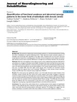
Two-phase closed thermosyphon (TPCT) as illustrated
in Figure 1 is essentially a gravity-assisted wickless heat
pipe, which utilizes the heat of evaporation and conden-
sation of the working fluid. Contrary to the conventional
heat pipe that uses the capillary force to return the
liquid to evaporator, the TPCT uses gravity to return
the condensate. Since the evaporator of a T PCT is
located in the lowest position, the gravitational force
will support the capillary force [1-3]. The TPCT has a
number of advantages such as simple structure, very
small thermal resistance, high efficiency, and low manu-
facturing costs. It has, therefore, been widely used in
various applications such as in industrial hea t recovery,
electronic component cooling, turbine blade cooling,
and solar heating systems [4-6]. The TPCT could be
modified to suit many more applications such as heat
exchangers and economizers. The first successful design
of economizer was used to increase efficiency of boilers
for stationary steam engines. It consisted of an array of
vertical cast iron tubes connected to two tanks of water
above and below, i n-between which the exhaust gases
from the boilers passed.
An economizer is a type of heat exchanger that can
be classified into four types: tubular heat exchanger
type (double pipe, shell and tube, and c oil tube), plate
heat exchanger type (gasketed, spiral, plate coil, and
lamella), extended surfac e heat exchanger type (tube-
fin and plate-fin), and regenerator type (fixed matrix
and rotary) [7-9]. Nada et al. [10] used a TPCT in a
solar collector with a shell and tube heat exchanger
and observed a uniform temperature distribution [10].
The performance of a TPCT depends upon the aspect
ratio (length to diameter) and the filling ratio (volume
of fluid to volume of evaporator). Another application
of the TPCT is in the energy recovery systems in air
conditioning plants in tropical countries. There, the
inlet air is pre-cooled by the cold exhaust stream
before it enters the refrigeration equipment [11-13].
Lukitobudi et al. [14] studied the heat exchange from
hot water to air using a TPCT, and Atipong et al. [15]
studied oscillating heat pipe in a wire-on-tube heat
exchanger. The results obtained by both groups
showed that after the heat recovery, the effectiveness
and heat transfer of the evaporator and condenser
increased by about 48%. Mostafa et al. [16] reported
that the economizer in the TPCT imposed limitation
* Correspondence:
1
Heat-Pipe and Thermal Tools Design Research Unit (HTDR), Division of
Mechanical Engineering, Faculty of Engineering, Mahasarakham University,
Thailand
Full list of author information is available at the end of the article
Parametthanuwat et al. Nanoscale Research Letters 2011, 6:315
/>© 2011 Parametthanuwat et al; licensee Springer. This is an Open Access article distributed under the terms of the Creative Commons
Attribution License (http://crea tivecommons.org/licenses/by/2.0), which pe rmits unrestricted use, distribution, and re prod uction in
any medium, provide d the origin al work is properly cited.
to the heat transfer due to the lower quality of the
working fluid accumulated inside. When nanofluids
were used as working fluids, they increased the ther-
mal and heat transfer capacities. Nanofluids are cre-
ated by suspending ultra-fine metallic or nonmetallic
particles typically of several tens o f nanometers in size,
in base fluids such as water, oil, and ethylene glycol.
Nanofluids were known to have enhanced the thermal
conductivity and convective heat transfer. However, to
obtain a sizable enhancement in thermal conductivity,
the particle volume concentration needs to be signifi-
cantly large, in the order of 0.5 vol% or above [17,18].
The distinct features of nanofluids are their stronger
temperature-dependent thermal conductivity than the
base fluid [19,20]. The thermal conductivity also
depends upon the concentration of the added surfac-
tant. In some instances, the nanofluids were unstable
and the nanoparticles found to have precipitated. A
surfactant improves the stability of a nanofluid by uni-
form dispersion of particles [21-23]. A surfactant can
adsorb gas in a liquid-gas interface and decrease the
interfacial tension. Some surfactants may flocculate in
the bulk solution [24,25].
The TPEC used in this study was a special type that
uses nanofluids in the thermosyphon to transfer heat
from evaporator to condenser without external energy
requirement. The primary objective of this study is to
design and test the TPEC that will increase the heat
transfer to water. The heat will be helpful to increase
effectiveness of the TPEC. This TPEC was designed
using a correlation of Kutateladza number (Ku).
TPEC design, experimental apparatus, and analysis
TPEC design
An economizer kit was designed using the Kutateladza
number (Ku) to predict the heat transfer of a TPCT.
The TPEC had three sections of equal size; the evapora-
tor, the adiabatic section, and the condenser, of 250 mm
× 250 mm × 250 mm (W × L × H). The thermosyphon
14
Condenser section
Evaporator sectio
n
Adiabatic section
Vapor flow
L
iquid flow by gravity force
Heat source
Heat sink
Pool
Figure 1 Schematic of the two-phase closed thermosyphon.
Table 1 System design conditions
Section of economizer Condition design
Length was 250 mm
Evaporator section Hot water flow was 80°C
Volumetric flow rate was 5 l/min
Adiabatic section Length was 250 mm
Length was 250 mm
Condenser section Cool water flow was 25°C
Volumetric flow rate was 1 l/min
Parametthanuwat et al. Nanoscale Research Letters 2011, 6:315
/>Page 2 of 10
was made with steel tubes of 12.7-mm ID. The details of
the economizer are shown in Table 1. Equation 1 was
used to calculate the heat transfer rate of the system.
Q
s
y
stem
=
Q
convevtion
+
Q
conductio
n
(1)
Then Equation 2 was used to calculate the convection
heat transfer rate of system.
Q
convevtion
=
•
m
C
p
(
T
out
− T
in
)
(2)
Now it becomes:
Q = f
(
•
m
, T
out
, T
in
)
The tube heat conduction loss was analyzed by Engi-
neering Sciences Data Unit Data Item No. 80013 (ESDU
81038) method [8]. The wall heat c onduction transfer
rate loss was calculated using Fourier’ law [26] as fol-
lows:
Q
conduction
= kA
T
(3)
Thus,
Q =
f (
k, A, T
)
The aim of this research was to find a correlation to
predict the heat transfer of the TPCT for a given num-
ber of tubes order to apply for TPEC. Ku is related to
the aspects ratio (
L
e
d
i
) that represents the distance of
physical motion for the working fluid (liquid and vapor).
The dimensionless groups encountered are: Prandtl
number, Pr (The ratio of m omentum diffusivity t o the
thermal diffusivity of liquid. It represents convection
heat transfer in a tube that occurs when the vapor bub-
ble moves from the evaporat or section to the condenser
section.), Bond number, Bo (The ratio of buoyancy force
to the surface tension force. Bo can be used to explain
boiling phenomena inside the evaporator section and
the state of vapor bubbles in nucleate boiling.), Jacob
number, Ja (The ratio of latent heat to sensible heat of
the working fluid. It represents the phase change of the
working fluid). Note that if all the groups have values
lower than 1; there will be no occurrence of phase
change. Peclet number, Pe,istheratioofbulkheat
transfer rates to conductive heat transfer rates. Conden-
sation Number, Co, is the liquid density ratio and hence
the gravitational component and homogeneous theory
for the momentum component (heat flux divided by the
product of mass flux and latent heat of vaporization).
The higher t he value of Co, the easier for the conden-
sate to return to the evaporator section. Drag coefficient,
Cd, is proportional to gravitational to internal forces
that predict momentum heat transfer rates dependent
on the physical motion. Archimedes number, Ar,
determines the motion of fluid and solids due to density
differences. Ar is depende nt on dimension to predicti on
the boiling phenomenon approaches boiling inside.
Ohnesorge number, Z, is proportional to viscous force to
inertial force with surface tension. Z is generally used in
momentum heat transfer rates and atomization. The
above-stated dimensionless numbers were correlated
with Ku in the form of Equat ion 4 to calculate the con-
vection heat transfer capacity of one tube.
Ku =0.04
Le
d
4.8
Pr
4.8
Bo
5.6
Ja
4.2
Pe
4.4
Co
5.6
Cd
3
Ar
0.8
Z
1.2
0
.
13
(4)
Thus,
q = f
L
e
d
i
, Pr, Bo, Ja, Pe, Co, Cd, Ar, Z
= Ku ×
ρ
v
h
fg
ρl − ρ
v
ρ
2
v
1
4
(5)
From Equations 4 and 5, the heat flux of the TPCT at
a vertical position can be evaluated from the Equation 6:
q =0.04
Le
d
4.8
Pr
4.8
Bo
5.6
Ja
4.2
Pe
4.4
Co
5.6
Cd
3
Ar
0.8
Z
1.2
0.13
×
ρ
v
h
fg
ρl − ρ
v
ρ
2
v
1
4
(6)
The calculations showed that the number of tubes for
TPEC is 12.
Experimental apparatus
This section describes experimental setup, the para-
meters of the study, and the procedure. The experimen-
tal plan is given in Table 2.
The nanofluid was produced by suspending metal or
metal oxide nanoparticles in a base fluid such as wat er.
The preparation involved several steps such as changing
the pH value of the suspension, using surfactant activa-
tors, and using ultrasonic vibration. For this study, the
nanofluid was sonicated for 5 h in ultrasonic bath. Silver
nanopowder (<100 nm particle size, 99.9% metals basis)
Table 2 Controlled and variable parameters
The tubes were arranged in a staggered
Operating temperature of 60,70 and 80°C
The controlled
parameters
Silver nanofluid concentration of 0.5 w/v%
Volumetric flow rate was 5 l/min in evaporator
section
Cool water flow was 25°C in condenser section
Working fluid = pure water, silver nanofluid
concentration of 0.5 w/v% and silver nanofluid
concentration of 0.5 w/v% mixed oleic acid
surfactant
The variable
parameters
Concentration of oleic acid surfactant were 0.5, 1,
1.5 w/v%
Volumetric flow rate were 1, 2, 5 l/min in
condenser section
Filling ratio = 30, 50, and 80% (by total length of
evaporator)
Parametthanuwat et al. Nanoscale Research Letters 2011, 6:315
/>Page 3 of 10
and oleic acid were obtained from Sigma-Aldrich Inc,
Milwaukee, Wisconsin: USA. The silver nanoparticles
were suspended in DI water with concentrations of
0.5 w/v% [16]. After that, the silver nanoparticles were
suspended into de-ionized water with concentrations of
0.5 w/v% mixed with oleic acid su rfactant concentration
of 0.5, 1, and 1.5 w/v%, respectively. The nanofluids
were stable for a long time.
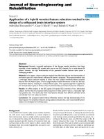
The TPCT in economizer was 12 tubes b y stand
upright the copper tube over thermal from hot bath.
After that, the TPCT were connected together with cop-
per pipe. The copper pipe was breached to insert a valve
mechanism that was used to evacuate and subsequently
charge the TPCT with the working fluids. The charging
procedure, as shown in Figure 2, consists of attaching a
vacuum pump to the valve.
Initially, the TPCT should be evacuated to about
0.010mmHg.Thetimerequired to achieve this level
depends on the pump capacity. Before filling the tube
with the working fluid, the system was leak-checked
with a vacuum gauge. This is done by closin g valve V
1
,
while leaving V
2
,V
3
,andV
4
open. Then to fill the
working fluid to the TPCT, open V
1
and close V
3
. After
the correct inventory of liquid was allowed into the
TPCT, V
1
was closed. Now valve V
3
was opened and
the vacuum pump was activated. While doing so the
valve V
4
was closed and the copper tube was dissected
and a welding cap was placed on it. Now the TPCT was
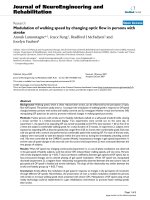
ready for experiment. Figure 3 shows the schematic dia-
gram of the experimental apparatus which consists of a
TPEC and peripheral devices. T he evaporator section is
the heat source with a hot bath. The condenser section
is the heat sink with a cold bath. The heat was supplied
by circulating water through the evaporator. The hot
water flow rates were controlled to achieve ± 4°C tem-
perature in the adiabatic section
The evaporator, the a diabatic, and the condenser sec-
tions of the TPEC were of equal aspect ratios. Thirteen
thermocouples were connected through a data logger
(Yokogawa DX200 with ±0.1°C accuracy, 20 channel
input and -200 to 1100°C measurement temperature
range). The type K thermocouples (OMEGA with ±0.1°
C accuracy) were attached to the inlet and the outlet of
the heating and cooling jackets as well as to the TPEC.
Altogether there were five temperature measuring points
on the condenser, five on the evaporator, and three on
the adiabatic section. A hot bath (TECHNE TE-10D
with an operating range of -40 to 120°C and ±0.1°C
accuracy) was used to pump hot water into the heating
jacket in the evaporator section and the cold bath
Figure 2 Schematic of initially the TPCT is filling working fluid.
Parametthanuwat et al. Nanoscale Research Letters 2011, 6:315
/>Page 4 of 10
(EYELA CA -1111, volume 6.0 l with an operating, tem-
perature range of -20 to 30°C and ±2°C accuracy) was
used to pump the cooling water into the cooling jacket
in the condenser section. The inlet temperature of the
cooling water was maintain ed at 20°C and a floating
Rota meter (Blue point S-4-103 for a flow rate of 0.5-5
l/min) was used to measure the f low rate of water dur-
ing the experiments. In order to calculate the heat trans-
fer rate of the TPEC, Equation 2) was used. Equa tion 7
was subsequently used to determine the calculation
error [16].
Q =
∂Q
∂
•
m
×
•
m
2
+
∂Q
∂T
out
× T
out
2
+
∂Q
∂T
in
× T
in
2
0.
5
(7)
The effectiveness analysis
To analyze the performance of the TPEC, the effective-
ness (ε) was calculated by the Number of Transfer Unit
Method (ε - NTU). The NTU is based on the heat
exchanger effectiveness defined as the ratio of actual
heat transfer in a heat exchanger to the maximum pos-
sibleamountofheatthatcouldbetransferredwithan
infinite area [26].
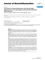
Figure 4a shows the fluid flow diagram and Figure 4b
shows the typical temperatu re profiles for a counter-
flow TPEC. For this scheme, the effectiveness can be
written as [27]:
ε =
C
c
(
Tc
o
− Tc
i
)
C
min
(
Th
i
− Tc
i
)
(8)
where the minimum heat capacity is defined as:
C
min
=
•
m
C
p
min
(9)
and the NTU is:
NTU =
UA
C
min
(10)
Thus,
ε = f
NTU,
C
min
C
max
The effectiveness of a counter flow heat exchanger is:
ε =
1 − exp
−NTU −
1 −
C
min
C
max
1 −
C
min
C
max
exp −
NTU
1 −
C
min
C
max
(11)
The experimental conditions are given in Table 2.
Figure 3 Schematic diagram of experimental apparatus.
Parametthanuwat et al. Nanoscale Research Letters 2011, 6:315
/>Page 5 of 10
Result and discussion
Effect of operating temperature on heat flux
Dependence of the operating temperature on the heat
flux of TPCE filled with the silver nanofluid mixed with
oleic acid (NF + OA) is shown in Figure 5. Also shown
are the data for water. In all cases the NF + OA shows
superior performance than pure water. The maximum
heat flux of 12 kW/m
2
has occurs with the OA 1 w/v%
nanofluid at the operating temperature of 80°C. From
this it can be seen that when the temperature was
increased from 60 to 80°C, the heat flux had increased
by different proportions. At this temperature interval,
the pool b oiling occurred that resulted high heat trans-
fer rates. Nanoparticles present in the liquid can
increase the surface area for heat absorption. As a
consequence the liquid will raise its temperature quicker
and start to boil. In the case of NF + OA, the OA will
stabilize the nanoparticles by uniformly distributing
them. This may cause increase in the thermal conduc-
tivity of the liquid, which in turn helps to raise the
liquid temperature.
Effect of filling ratios on heat flux
Figure 6 shows the effect of filling ratios on heat flux.
The maximum heat flux of 12 kW/m
2
has occurred at
the filling ratio o f 50% with the NF + OA 1 w/v%. This
is approximately 60% higher than water. Filling ratios of
30 and 80% presumably caused dry out and flooding of
the evaporator [1,5,13] which made the 50% filling ratio
as the most favorable.
Condenser section
Evaporator
section
Adiabatic section
(
a
)(
b
)
12
ih
T
,
Figure 4 (a) Flow diagram of experimental apparatus. (b) Temperature distribution for a counter flow TPEC [27].
0
2
4
6
8
10
12
14
60 70 80
Operating temperature(
o
C)
Heat flux (kW/m
2
)
Water
NF
NF+OA 0.5%w/v
NF+OA 1%w/v
NF+OA 1.5%w/v
Figure 5 Relationship between operating temperature and
heat flux. Volumetric flow rate = 1 l/min, filling ratio = 50%.
0
2
4
6
8
10
12
14
30 50 80
Fillin
g
ratios(%)
Heat flux(kW/m
2
)
Water NF
NF+OA 0.5%w/v NF+OA 1%w/v
NF+OA 1.5%w/v
Figure 6 Relationship between filling ratios and heat flux.
Volumetric flow rate = 1 l/min, operating temperature = 80°C.
Parametthanuwat et al. Nanoscale Research Letters 2011, 6:315
/>Page 6 of 10
Effect of volumetric flow rate on heat flux
Relationship between the volumetric flow rate and the
heat flux of TPEC at 80°C is shown in Figure 7. The
heat flux has i ncreased with the volumetric flow rate
suggesting that the thermosyphon efficiency increasing
with the same. Consider the case of 1 w/v% nanofluid,
where at 5 l/min, the resulting heat flux was 25 kW/m
2
.
The increase of the maximum heat flux with the volu-
metric flow rate can be attributed to the increase of the
operating temperature. As the operating temperature
increases, the system approaches boiling.
Effect of concentration on effectiveness
The experimental data for effe ctiveness versus the con-
centration of oleic acid surfactant in nanofluid are pre-
sented in Figure 8. The maximum effectiveness of 0.3
has occurred at OA concentration of 1 w/v%, which was
better than OA concentrations of 0, 0.5, and 1.5 w/v%.
This behavior could possibly be caused by the change in
viscosity. When the OA concentration was smaller or
larger than 1 w/v%, it was either insufficient to stabilize
the nanofluid or introduced excessive oil to the surface
that suppressed bubble movement. The possible influ-
ence of surface tension is explained in the following
section.
Effect of operating temperature on effectiveness
The experimental data and theoretical predictions for
the effect of operating temperature on the effectiveness
of TPEC are demonstrated in Figure 9. The maximum
effectiveness of 0.3 has occurred with the OA concen-
tration of 1 w/v% and at 80°C. The effectiveness
increased with the operating temperature. This is due to
the onset of boiling in the TPCT and also due to the
reduction of surface tension that made the bubbles
easier to move upwards. In particular the addition of
OA further reduced the surface tension that would
cause early boiling. Figure 9 further shows that at 80°C,
the effectiveness of water was 80% lower than the the-
ory, whereas the effectiveness of NF + OA 1 w/v% was
only 40% lower. Hence, the NF + OA has performed
better than water. This demonstrates the benefit of NF
+ OA as a working fluid in TPCT.
Effect of filling ratios on effectiveness
Figure 10 presents the experimental data for the effec-
tiveness versus filling ratios. The maximum effectiveness
of 0.3 has occurred at the filling ratio of 50% with the
nanofluid mixed with OA 1 w/v%. The OA molecule
has long chain length that helps to stabilize the nano-
fluid. From this data it suggests that 1 w/v% of OA is
the optimal concentration.
0
5
10
15
20
25
30
12.55
Volumetric flow rate
(
liter/min
)
Heat flux(kW/m
2
)
Water
NF
NF+OA 0.5%w/v
NF+OA 1%w/v
NF+OA 1.5%w/v
Figure 7 Relationship between volumetric flow rate and heat
flux. Operating temperature = 80°C, filling ratio = 50%.
0
0.1
0.2
0.3
0.4
0.5
00.511.5
Concentration
(
%w/v
)
Effectiveness
Volume tric flow ra te 1 lite r/min
Volumetric flow rate 2.5 liters/min
Volume tric flow ra te 5 lite rs /min
Figure 8 Relationship between concentration (%w/v) and
effectiveness. Operating temperature = 80°C, filling ratio = 50%.
0
0.1
0.2
0.3
0.4
0.5
0.6
60 70 80
O
p
eratin
g
tem
p
erature(
o
C)
Effectiveness
Water
NF
NF+OA 0.5%w/v
NF+OA 1%w/v
NF+OA 1.5%w/v
Theory of effectiveness-NTU
Figure 9 Relationship between operating temperature and
effectiveness. Volumetric flow rate = 1 l/min, filling ratio = 50%.
Parametthanuwat et al. Nanoscale Research Letters 2011, 6:315
/>Page 7 of 10
Effect of volumetric flow rate on effectiveness
It can be seen from Figure 11 that the effectiveness of
TPEC has strong dependence on the volumetr ic flow
rate. The maximum effectiveness obtained from experi-
mentswas0.3thatoccurredat1l/min,forwhichthe
theoretical prediction was 0.5. When the flow rate was
increased, the amount of water in the condenser also
increased that caused the reduction of the effectiveness.
This observation agrees with Equation 8.
Conclusions
A TPEC was designed using a correlation of Kutateladza
number (Ku) for the prediction of heat transfer of the
TPCT. Experiments were conducted on the TPEC using
various working fluids to study the effects of various
parameters on the heat flux and the effectiveness. It was
found that pure water gave the lowest values for heat
flux, whereas the silver nanofluid and the silver nano-
fluid containing oleic acid gave the higher heat fluxes.
In particular, the silver nanofluid containing 1 w/v%
oleic acid exhibited the best performance in all experi-
ments. Moreover 80°C operating temperature, 50% fill-
ing ratio, 5 l/min volumetricflowratewereprovedto
be the optimum working conditions that yielded the
maximum heat flux from this TPEC. Furthermore, it
was found that the highest value for effectiveness was
also displayed by the silver nanofluid containing 1 w/v%
oleic acid at 80°C operating temperature, 50% filling
ratio, and 1 l/min volumetric flow rate.
List of symbols
A Total heat transfer area, surface area of eva porator
(m
2
)
C Capacity rate (kJ(s°C)
-1
)
C
p
Specific heat capacity constant pressure, (J(kg °C)
-1
)
D Diameter (m)
h
fg
Latent heat of vaporization, (kJ · kg
-1
)
k Thermal conductivity (W/mK)
L Length of thermosyphon (mm)
L
c
Characteristic length (m)
•
m
Mass flow rate (kg · s
-1
)
NF Silver nanofluid
NF + OA Silver nanofluid with oleic acid
NF + OA 0.5 w/v% Silver nanofluid with oleic acid
concentration 0.5 w/v%
NF + OA 1 w/v% Silver nanofluid with oleic acid con-
centration 1 w/v%
NF + OA 1.5 w/v% Silver nanofluid with oleic acid
concentration 1.5 w/v%
OA Oleic acid
Q Heat transfer rate (W)
q Heat flux (kW/m
2
)
T
out
Outlet temperature at condenser section (°C)
T
in
Inlet temperature at condenser section (°C)
T
v
Operating temperature (°C)
ΔT Temperature difference (°C)
U Overall heat transfer coefficient (W · m
-2
·K)
V Velocity (m · s
-1
)
Greek symbols
r Density (kg · m
-3
)
μ Viscosity (Pa · s)
s Surface tension (N · m
-1
)
ε Effectiveness of economizer
Subscripts
a Adiabatic
c Condenser, cold fluid
e Evaporator
h Hot fluid
iin
l Liquid
max Maximum
0
0.1
0.2
0.3
0.4
0.5
0.6
30 50 80
Fillin
g
ratios(%)
Effectiveness
Water
NF
NF+OA 0.5%w/v NF+OA 1%w/v
NF+OA 1.5%w/v
Figure 10 Relationship between filling ratios and effectiveness.
Volumetric flow rate = 1 l/min, operating temperature = 80°C.
0
0.1
0.2
0.3
0.4
0.5
0.6
12.55
Volumetric flow rate
(
liter/min
)
E
ff
ect
i
veness
Water
NF
NF+OA 0.5%w/v
NF+OA 1%w/v
Figure 11 Relationship between volumetric flow rate and
effectiveness. Operating temperature = 80°C, filling ratio = 50%.
Parametthanuwat et al. Nanoscale Research Letters 2011, 6:315
/>Page 8 of 10
min Minimum
o out
v Vapor
Ar, Archimedes number =
Ar =
g × ρ
s
× L
3
μ
2
(
ρ
s
− ρ
f
)
Bo, Bond number =
D
g
ρ
l
− ρ
v
σ
1
2
Co, Condensation number =
h
k
μ
2
gρ
2
1
3
Ja, Jacob number =
h
fg
C
p
,l
T
v
Ku, Kutateladza number =
⎡
⎢
⎢
⎢
⎢
⎢
⎢
⎣
q
ρ
v
h
fg
ρ
l
− ρ
v
ρ
2
v
1
4
⎤
⎥
⎥
⎥
⎥
⎥
⎥
⎦
Aspect ratio =
L
e
d
i
Pr, Prandtl number =
μ
1
C
p,l
k
1
Pe, Peclet number =
L.VρC
p
k
Cd, Drag number =
g
(ρ − ρ
f
)L
ρ
V
2
Z, Ohensorge number =
μ
(
g ρ L σ
)
1/3
Abbreviations
NF: nanofluid; OA: oleic acid; TPEC: thermosyphon for economizer; TPCT:
two-phase closed thermosyphon.
Acknowledgements
Financial support from the Thailand Research Fund through the Royal
Golden Jubillee Ph.D. Program (Grant No. PHD/0340/2550) to TP and SR is
acknowledged. TP, SR were also supported generously by the Faculty of
Engineering, Mahasarakham University, Thailand and Institute of Particle
Science & Engineering, University of Leeds, United Kingdom.
Author details
1
Heat-Pipe and Thermal Tools Design Research Unit (HTDR), Division of
Mechanical Engineering, Faculty of Engineering, Mahasarakham University,
Thailand
2
Bio-Energy Research Laboratory (BERL), Division of Mechanical
Engineering, Faculty of Engineering, Mahasarakham University, Thailand
3
Institute of Particle Science & Engineering, University of Leeds, Leeds, UK
Authors’ contributions
TP conducted the experiments. SR helped and supervised TP for
experiments. AP and YD supervised and facilitated the work in their
respective institutions. SW revised and edited the manuscript. All authors
read and approved the final manuscript.
Competing interests
The authors declare that they have no competing interests.
Received: 13 October 2010 Accepted: 7 April 2011
Published: 7 April 2011
References
1. Payakaruk T, Teedtoon P, Ritthidech S: Correlation to predict heat transfer
characteristic of an inclined closed two-phase thermosyphon at normal
operating conditions. Appl Therm Eng 2000, 20:781-790.
2. Ristoiu D, Ristoiu T, Coama C, Cenan D: Experimental investigation of
inclination angle on heat transfer characteristics of closed two-phase
thermosyphon. 5th General Conference of the Balkan Physical , August 25-
29:1643-1646
3. Khandekar S, Joshi YM, Mehta B: Thermal performance of closed two-
phase thermosyphon using nanofluids. Therm Sci 2008, 47:695-667.
4. Jiao B, Qiu LM, Zhang XB, Zhang Y: Investigation on the effect of filling
ratio on the steady-state heat transfer performance of a vertical two-
phase closed thermosyphon. Appl Therm Eng 2008, 28:1417-1426.
5. Paramatthanuwat T, Boothaisong S, Rittidech S, Booddachan K: Heat
transfer characteristics of a phase closed thermosyphon using de
ionized water mixed with silver nano heat mass transfer. Heat Mass
Transf 2010, 46:281-285.
6. Milanez FH, Mantenli MBH: Thermal characteristics of a thermosyphon
heated enclosure. Int J Therm Sci 2006, 45(5):504-510.
7. da Silva AK, Mantelli MBH: Thermal applicability of two-phase
thermosyphons in cooking chambers experimental and theoretical
analysis. Appl Therm 2004, 24(9):717-733.
8. Reay D, Kew P: Heat pipe, Theory, Design And Application, Fifth edition,
Butterworth-Heinemann. Jordan Hill, Oxford, UK; 2006.
9. Mantelli MBH, Lopes A, Martins GJ, Zimmerman R, Baungartner R,
Landa HG: Thermosyphon kit for conversion of electrical bakery ovens to
gas. Proceedings of the 8th International Heat Pipe Symposium Japan; 2006,
193-198.
10. Nada SA, El-Ghetany HH, Hussein HMS: Performance of a two-phase
closed thermosyphon solar collector with a shell and tube heat
exchanger. Appl Therm Eng 2004, 24(13):1959-1968.
11. Parametthanuwat T, Rittidech S, Booddachan K: Thermosyphon installation
for energy thrift in a smoked fish sausage oven (TISO). Energy 2010,
35:2836-2842.
12. Fernando H, Mantenli MBH: Thermal characteristics of a thermosyphon
heated enclosure. Int J Therm Sci 2005, 45:504-5108.
13. Noie-Baghban SH: Heat transfer characteristics of a two phase closed
thermosyphon. Appl Therm Eng 2005, 25:495-506.
14. Lukitobudi AR, Akbarzadeh A, Jhonson PW, Hendy W: Design, construction
and testing of a thermosyphon heat exchanger for medium
temperature heat recovery in bakeries. Heat Recovery Systems CHP 1995,
15:481-491.
15. Atipong N, Sanparwat V, Nat V, Tanongkiat K: Use of oscillating heat pipe
technique as extended surface in wire-on-tube heat exchanger for heat
transfer enhancement. Int
Commun Heat Mass 2010, 37:287-292.
16. Mostafa A, Abd Ei-Baky , Mousa M: Heat pipe heat exchanger for heat
recovery in air conditioning. Appl Therm Eng 2007, 27:795-801.
17. Parametthanuwat T, Rittidech S, Pattiya A: A correlation to predict heat-
transfer rates of a two-phase closed thermosyphon (TPCT) using silver
nanofluid at normal operating conditions. Int J Heat Mass Transf 2010,
539(21-22):4960-4965.
18. Kwak K, Kim C: Viscosity and thermal conductivity of copper oxide
nanofluid dispersed in ethylene glycol. Korea-Australia Rheol J 2005,
17(2):35-40.
19. Kang SW, Wei WC, Tsai SH, Yang SY: Experimental investigation of silver
nano-fluid on heat pipe thermal performance. Appl Therm Eng 2006,
26:2377-2382.
20. Kim SJ, Bang IC, Buongiorno J, Hu LW: Study of pool boiling and critical
heat flux enhancement in Nanofluids. Bull Pol Ac Tech 2007,
55(2):211-216.
21. Lin YH, Kang SW, Chen HL: Effect of silver nano-fluid on pulsating heat
pipe thermal performance. Appl Ther Eng 2008, 28:1312-1317.
22. Li XF, Zhua DS, Wang XJ, Wanga N, Gaoa JW, Lia H: Thermal conductivity
enhancement dependent pH and chemical surfactant for Cu-H
2
O
nanofluids. Thermochimica Acta 2008, 469:98-103.
23. Qi Y, Kawaguchi Y, Lin Z, et al: Enhanced heat transfer of drag reducing
surfactant solutions with fluted tube-in-tube heat exchanger. Int J Heat
Mass Transf 2001, 44:1495-1505.
24. Hwang Y, Lee JK: Production and dispersion stability of nanoparticles in
nanofluids. Powder Technol 2008, 186(2):145-153.
Parametthanuwat et al. Nanoscale Research Letters 2011, 6:315
/>Page 9 of 10
25. Nakoryakov VE, Grigoryeva NI, Bufetov NS, Dekhtyar RA: Heat and mass
transfer intensification at steam absorption by surfactant additives. Int J
Heat Mass Transf 51:5175-5181.
26. Faghri A: Heat Pipe Science and Technology. Taylor & Francis,
Washington, DC;, 1 1995.
27. Incropera FP, Dewitt DP: Fundamental of Heat and Mass Transfer. 4 edition.
New York: Wiley; 1996.
doi:10.1186/1556-276X-6-315
Cite this article as: Parametthanuwat et al.: Application of silver
nanofluid containing oleic acid surfactant in a thermosyphon
economizer. Nanoscale Research Letters 2011 6:315.
Submit your manuscript to a
journal and benefi t from:
7 Convenient online submission
7 Rigorous peer review
7 Immediate publication on acceptance
7 Open access: articles freely available online
7 High visibility within the fi eld
7 Retaining the copyright to your article
Submit your next manuscript at 7 springeropen.com
Parametthanuwat et al. Nanoscale Research Letters 2011, 6:315
/>Page 10 of 10