Wang et al. Nanoscale Research Letters 2011, 6:367 potx
Bạn đang xem bản rút gọn của tài liệu. Xem và tải ngay bản đầy đủ của tài liệu tại đây (657.75 KB, 5 trang )
NANO EXPRESS Open Access
Freestanding HfO
2
grating fabricated by fast
atom beam etching
Yongjin Wang
1,2*
, Tong Wu
2
, Yoshiaki Kanamori
2
and Kazuhiro Hane
2
Abstract
We report here the fabrication of freestanding HfO
2
grating by combining fast atom beam etching (FAB) of HfO
2
film with dry etching of silicon substrate. HfO
2
film is deposited onto silicon substrate by electron beam
evaporator. The grating patterns are then defined by electron beam lithography and transferred to HfO
2
film by
FAB etching. The silicon substrate beneath the HfO
2
grating region is removed to make the HfO
2
grating suspend
in space. Period- and polarization-dependent optical responses of fabricated HfO
2
gratings are experimentally
characterized in the reflectance measurements. The simple process is feasible for fabricating freestanding HfO
2
grating that is a potential candidate for single layer dielectric reflector.
PACS: 73.40.Ty; 42.70.Qs; 81.65.Cf.
Keywords: HfO
2
film grating, fast atom beam etching
I. Introduction
As an excellent optical material, hafnium oxide (HfO
2
)
film presents high laser damage threshold, thermal and
chemical stability [1-3]. Since HfO
2
film is transparent
from visible to infrared range, it often servers as the
high refractive index material for fabricating multilayer
reflection mirror [4,5 ], or acts as the waveguiding layer
for the realization of guide mode resonant optical f ilter
[6]. These optical d evices are originated from the film
deposition techniques of HfO
2
material. On the other
hand, freestanding structures are greatly developed as
the promising candidates for producing resonant filter
[7,8] or in place of a traditional top distributed Bragg
reflector to reflect light within a cavit y [9-12]. As a sin-
gle layer dielectric mirror, freestanding structures are
often sandwiched with air on top and bottom. Com-
pared with multilayer reflection mirror, freestanding
structure is more compact and reflects light more effi-
ciently [13]. The high refractive i ndex contrast between
HfO
2
/air also endows the freestanding HfO
2
micro/nano
structures with the capacity to function as single layer
dielectric reflector or guide mode resonant filter. HfO
2
film is a hard material, and usually serves as etch stop
layer [14,15]. Recently, focused ion beam (FIB) milling
was developed to fabricate sub-micron HfO
2
gratings
[16]. In FIB milling, micro/nano structures could be
achieved on various material systems by physically
removing the sample material with a metal ion beam.
However, FIB milling is a single process and difficult to
be compatible with other fabrication processes for mass
production. Moreover, this etching technology is expen-
sive and time-consuming.
We demonstrate here a simple way to fabricate free-
standing HfO
2
grating by a combination of fast atom
beam (FAB) etching and dry etching of silicon. FAB
etching, which is capable of high anisotropy etching
because it uses neutral particles or atoms for dry etch-
ing, is used as a well-controlled, low-damage etching
technique to manufacture HfO
2
film [17,18]. To make
grating structures freely suspend, the silicon substrate
beneath the Hf O
2
grating region is removed in associa-
tion of anisotropic and isotropic dry etching of silicon.
Period- and polarization-dependent optical responses
are experimentally characterized in reflectance
measurements.
II. Fabrication
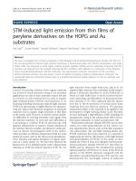
Figure 1 schematically illustrates the fabrication process
of freestanding HfO
2
gratings, which are implemented
on a silicon substrate. The process starts from the blank
* Correspondence:
1
Institute of Communication Technology, Nanjing University of Posts and
Telecommunications, Nanjing, Jiang-Su 210003, People’s Republic of China
Full list of author information is available at the end of the article
Wang et al. Nanoscale Research Letters 2011, 6:367
/>© 2011 Wang et al; licensee Springer. This is an Open Access article distributed under the terms of the Creative Commons Attrib ution
License ( which permits unrestricted use, distribution, and reproduction in any medium,
provided the original work is prope rly cited.
deposition of HfO
2
film on the silicon substrate with an
electron beam (EB) evapora tor (step a). A positive EB
ZEP520A resist is then spin-coated onto the HfO
2
layer,
and grating patterns are patterned in ZEP520A resist
using EB lithography (step b). Subsequently, the patterns
are transferred to Hf O
2
layer by FAB etching (step c).
FAB etching, which is generated by the neutralization of
ions extracted from direct-current SF
6
plasma (Ebara,
FAB-60 ml), is performed with a SF
6
gas of 5.6 sccm at
the high voltage of 2.0 KV and accelerated current of 20
mA. The HfO
2
gratings are th en released by a combina-
tion of anisotropic and isotropic dry etching of silicon,
which makes the HfO
2
grating freely suspend (step d).
The anisotropic etching of silicon is carried out to pro-
duce vertical silicon trenches and the isotropic etching
is used to release the Hf O
2
gratings laterally, where the
remained EB resist and HfO
2
film act as the etching
mask. The freestanding HfO
2
gratings are finally gener-
ated by removing the residual resist (step e).
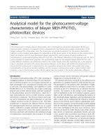
III. Experimental results and discussion
Figure 2(a) shows one scanning electron microscope
(SEM) image of the cross-section of the HfO
2
/Si plat-
form. The thickness of HfO
2
film is about 180 nm. The
FAB is made up of the energetic neutral beam flux with
high directionality and thus, the manufacturing method
is capable of high anisotropic etching of HfO
2
film.
There is no special requirement of etching mask, and
EB resist can serve as an etching mask. Fabricated free-
standing HfO
2
grating illustrated in Figure 2(b) consi sts
of 60-period grating with the grating length of 60 μm,
and air is the low refractive index materials on the bot-
tom and top. The grating period and the grating w idth
are expressed by P and W. The duty ratio D(= W/P)is
defined as the ratio of the grating width to the grating
period. Figures 2(c) and 2(d) illustrate the zoom-in SEM
images of the fabricated freestanding HfO
2
gratings,
where the grating period is 1040 nm and the grating
height is about 180 nm, the same as the HfO
2
film
thickness. Since the thickness of EB resist varies due to
the proximity effect in EB lithography, the HfO
2
gratings
generated in reality are trapezoidal pro files and deviate
from the designed rectangular elements. The corre-
sponding bottom grating widths W
b
are measured ~780
nm and ~670 nm, and the top grating widths W
t
are
about 500 nm and 440 nm, respectively.
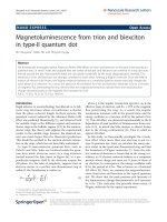
The simple process is scalable for fabricating sus-
pended HfO
2
nanostructures, and facilitates monolithic
integration of optoelectronic devices on various material
systems. Figure 3(a) shows freestanding circular HfO
2
grating, and the inset is the zoom-in SEM image of cir-
cular grating with the grating period of 500 nm, where
cross arms are connec ted to the freestanding circular
gratings. From the fabrication point of view, the under-
cut of silicon beneath the HfO
2
grating region tends to
be difficult when the duty ratio D increases. On the
other hand, the long HfO
2
grating beams are in the ten-
dency of being fragile, and the deflection and fracture of
HfO
2
grating beams take place when the duty ratio D
decreases. According to our experimental results, the
duty ratio D is feasible in the r ange of 0.3~0.7 to suc-
cessfully achieve freestanding HfO
2
gratings. Moreover,
anisotropic and isotropic dry etching of silicon will
result in rough silicon surface and large variation i n air-
gap between HfO
2
grating and silicon beneath HfO
2
grating region, which will degrade the optical perfor-
mance. In association of deposition and etching techni-
ques, this fabrication issue can be solved and such
freestanding HfO
2
nanostructures are possible to be
incorporated into other material system for serving as
Silicon
HfO
2
Resist
RIE
FAB
(a)
(b)
(c)
(d)(e)
Figure 1 Fabrication process of freestanding HfO
2
grating.
Wang et al. Nanoscale Research Letters 2011, 6:367
/>Page 2 of 5
the top mirror. Freestanding HfO
2
photonic crystals illu-
strated in Figure 3(b) are realized on a GaN-on-silicon
platform, and the inset is the zoom-in SEM image of
freestanding photonic crystal structures with the period
of 600 nm. Between HfO
2
film and GaN layer, one
sacrificial film is inserted. After removing the sacrificial
layer, HfO
2
photonic crystals are freely suspended and
the airgap is control led by the sacrificial layer thickness.
These results indicate that the proposed process is feasi-
ble to fabricate freestanding HfO
2
nanostructures.
It should be noted that the HfO
2
gratings are designed
by using rigorous coupled wave analysis (RCWA)
method with a commercial code. The generated HfO
2
gratings deviate much from the ideal elements used for
RCWA simulations (not shown here). The trapezoidal
grating profiles, roughness of the grating sidewalls, and
Figure 2 SEM images of fabricated freestanding HfO
2
grating. (a) cross section SEM image of HfO
2
/Si platform; (b) a fabricated freestanding
HfO
2
grating; (c) and (d) zoom-in SEM images of 1040 nm period HfO
2
gratings with the grating widths W
t
of 500 nm and 440 nm, respectively.
Figure 3 SEM images of fabricated freestanding HfO
2
nanostructures. (a) SEM image of a freestanding circular HfO
2
grating, the inset is the
zoom-in SEM image of circular grating with the grating period of 500 nm; (b) a freestanding HfO
2
photonic crystal slab on a GaN-on-silicon
platform, the inset is the zoom-in SEM image of HfO
2
photonic crystals with the grating period of 600 nm.
Wang et al. Nanoscale Research Letters 2011, 6:367
/>Page 3 of 5
variations in silicon surface beneath the grating region
degrade the optical performance and result in the spec-
tral shift. Moreover, the available spectral range is from
1460 nm to 1580 nm in our measurement system.
Hence, a variety of HfO
2
gratings with different grating
parameters are fabricated f or optical characterization.
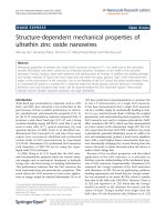
Figure 4(a) illustrates one optical micrograph of fabri-
cated HfO
2
gratings, where the upper two gratings are
with the grating widths W
t
of 440 nm. The color varies
as the grating width changes. The grating widths W
t
are
about 500 nm for t he bottom gratings, and the grating
periods are 1020 nm and 1040 nm, respectively. The
inset is the magnified view o f fabricated HfO
2
grating,
where the grating period P is 1020 nm and the grating
width W
t
is about 440 nm. A tunable laser (Agilent
81682A) is used as the ligh t source to characte rize the
optical response of the fabricated freestanding HfO
2
gratings in the telecommunication range. The polarized
light beam is incident onto the HfO
2
gratings by an
infrared objective lens with a numerical aperture of 0.25,
and an infrared CCD camera is installed on the setup to
acquire sample images. The reflected light is collected
and sent to an infrared spectrometer. The experimental
spectra are normalized to those of a commercial g old
mirror. Figure 4(b) illustrates t he reflectance spectra of
freestanding HfO
2
gratings, where the grating widths W
t
are a bout 440 nm. Taken 1040 nm period HfO
2
grating
as an example, a broad reflection band that is deter-
mined by the refractive index contrast is observed under
transverse electric (TE) polarization (TE is polarized in
the plane of the grating and pa rallel to the grating lines)
[19]. Two sharp reflection dips are found at 1486 nm
and 1562.7 nm with measured reflectance of 10.7% and
4.6%, respectively. Measured reflectances are over 70%
in the range of 1499.2 m~1539.5 nm. Since fabricated
HfO
2
gratings are configured with one-dimensional
symmetry, their optical responses are polarization
dependent, which are measured by rotating the sample
1460 1480 1500 1520 1540 1560 1580
0
20
40
60
80
100
Freestanding HfO
2
grating
Reflectance (%)
Wavelength (nm)
P:1020nm-TE
P:1040nm-TE
P:1020nm-TM
P:1040nm-TM
(b)
Figure 4 Optical characterizations of fabricated freestanding HfO
2
gratings. (a) optical micrograph of freestanding HfO
2
gratings; (b) the
reflectance spectra of freestanding HfO
2
gratings in the telecommunication range.
Wang et al. Nanoscale Research Letters 2011, 6:367
/>Page 4 of 5
with an angle of 90° with respect to initial measurement.
The ref lection band shifts and the shape changes under
transverse magnetic (TM) polarization (TM is polarized
in the plane of the grating and perpendicular to the
grating lines). The linear grating reflector is useful for
controlling the polarization on a vertical cavity surface
emitting device. A blue-shift is observed in reflectance
spectra with decreasing t he grating period. As the grat-
ing period decreases from 1040 nm to 1020 nm, t he
broad reflection band shifts to shorter wavelength.
These results indicate that freestanding HfO
2
grating is
a promising candidate for single layer dielectric
reflector.
IV. Conclusions
In summary, freestanding HfO
2
gratings are realized by
a combination of FAB etching of HfO
2
film and dry
etching of silicon substrate. Period- and polarization-
dependent optical responses of fabricated HfO
2
gratings
are experimentally characterized in the reflectance mea-
surements. The simple process is feasible for fabricating
freestanding HfO
2
grating that is a potential candidate
for single layer dielectric reflector.
Acknowledgements
This work was partially supported by the JSPS Research Project (19106007
and P09070) and NJUPT Research Project (NY211001).
Author details
1
Institute of Communication Technology, Nanjing University of Posts and
Telecommunications, Nanjing, Jiang-Su 210003, People’s Republic of China
2
Department of nanomechanics, Tohoku University, Sendai 980-8579, Japan
Authors’ contributions
YW carried out the device design and fabrication, performed the optical
measurements, and drafted the manuscript. TW carried out HfO
2
film
evaporation. YK participated in its design and optical characterization. KH
conceived of the study, and participated in its design and coordination. All
authors read and approved the final manuscript.
Competing interests
The authors declare that they have no competing interests.
Received: 17 December 2010 Accepted: 28 April 2011
Published: 28 April 2011
References
1. Alvisi M, Scaglione S, Martelli S, Rizzo A, Vasallelli L: “Structural and optical
modification in hafnium oxide thin films related to the momentum
parameter transferred by ion beam assistance”. Thin Solid Films 1999,
354:19.
2. Gilo M, Croitoru N: “Study of HfO
2
films prepared by ion-assisted
deposition using a gridless end-hall ion source”. Thin Solid Films 1999,
350:203.
3. Wang Y, Lin Z, Cheng X, Xiao H, Zhang F, Zou S: “Study of HfO
2
thin films
prepared by electron beam evaporation”. Appl Surf Sci 2004, 228:93.
4. Liu S, Jin Y, Cui Y, Ma J, Shao J, Fan Z: “Characteristics of high reflection
mirror with an SiO
2
top layer for multilayer dielectric grating”. J Phys D:
Appl Phys 2007, 40:3224.
5. Chen R, Sun HD, Wang T, Hui KN, Choi HW: “Optically pumped ultraviolet
lasing from nitride nanopillars at room temperature”. Appl Phys Lett 2010,
96:241101.
6. Priambodo PS, Maldonado TA, Magnusson R: “Fabrication and
characterization of high-quality waveguide-mode resonant optical
filters”. Appl Phys Lett 2003, 83:3248.
7. Crozier KB, Lousse V, Kilic O, Kim S, Fan S, Solgaard O: “Air-bridged
photonic crystal slabs at visible and near-infrared wavelengths”. Phys Rev
2006, B73:115126.
8. Hsu C, Liu Y, Wang C, Wu M, Tsai Y, Chou Y, Lee C, Chang J: “Bulk-
micromachined optical filter based on guided-mode resonance in
silicon-nitride membrane”. J Lightwave Technol 2006, 24:1922.
9. Aritaa M, Ishida S, Kako S, Iwamoto S, Arakawa Y: “AlN air-bridge photonic
crystal nanocavities demonstrating high quality factor”. Appl Phys Lett
2007, 91:051106.
10. Boutami S, Benbakir B, Leclercq J, Viktorovitch P: “Compact and
polarization controlled 1.55 μm vertical-cavity surface-emitting laser
using single-layer photonic crystal mirror”. Appl Phys Lett 2007, 91:071105.
11. Huang MCY, Zhou Y, Chang-Hasnain CJ: “A surface-emitting laser
incorporating a high-index-contrast subwavelength grating”. Nature
Photon 2007, 1:119.
12. Chung I, Mørk J: “Silicon-photonics light source realized by III-V/Si-
grating-mirror laser”. Appl Phys Lett 2010, 97:151113.
13. Willner AE: “All mirrors are not created equal”. Nature Photon 2007, 1:87.
14. Shih KK, Chieu TC, Dove DB: “Hafnium dioxide etch-stop layer for phase-
shifting masks”. J Vac Sci Technol B 1993, 11:2130.
15. Britten JA, Nguyen HT, Falabella SF, Shore BW, Perry MD, Raguin DH: “Etch-
stop characteristics of Sc
2
O
3
and HfO
2
films for multilayer dielectric
grating applications”. J Vac Sci Technol A 1996, 14(5):2973.
16. Chaganti K, Salakhutdinov I, Avrutsky I, Auner G, Mansfield John: “Sub-
micron grating fabrication on hafnium oxide thin-film waveguides with
focused ion-beam milling”. Opt Express 2006, 14:1505.
17. Ono T, Orimoto N, Lee S, Simizu T, Esashi M: “RF-plasma-assisted fast atom
beam etching”. Jpn J Appl Phys 2000, 39:6976.
18. Wang Y, Kanamori Y, Ye J, Sameshima H, Hane K: “Fabrication and
characterization of nanoscale resonant gratings on thin silicon
membrane”. Optics Express 2009, 17:4938.
19. Chen L, Huang MCY, Mateus CFR, Chang-Hasnain CJ, Suzuki Y: “Fabrication
and design of an integrable subwavelength ultrabroadband dielectric
mirror”. Appl Phys Lett 2006, 88:031102.
doi:10.1186/1556-276X-6-367
Cite this article as: Wang et al.: Freestanding HfO
2
grating fabricated by
fast atom beam etching. Nanoscale Research Letters 2011 6:367.
Submit your manuscript to a
journal and benefi t from:
7 Convenient online submission
7 Rigorous peer review
7 Immediate publication on acceptance
7 Open access: articles freely available online
7 High visibility within the fi eld
7 Retaining the copyright to your article
Submit your next manuscript at 7 springeropen.com
Wang et al. Nanoscale Research Letters 2011, 6:367
/>Page 5 of 5