Báo cáo hóa học: " Growth and characterization of gold catalyzed SiGe nanowires and alternative metal-catalyzed Si nanowires" pot
Bạn đang xem bản rút gọn của tài liệu. Xem và tải ngay bản đầy đủ của tài liệu tại đây (2.18 MB, 9 trang )
NANO EXPRESS Open Access
Growth and characterization of gold catalyzed
SiGe nanowires and alternative metal-catalyzed
Si nanowires
Alexis Potié
1,3*
, Thierry Baron
1*
, Florian Dhalluin
1
, Guillaume Rosaz
1
, Bassem Salem
1
, Laurence Latu-Romain
1
,
Martin Kogelschatz
1
, Pascal Gentile
2
, Fabrice Oehler
2
, Laurent Montès
3
, Jens Kreisel
4
, Hervé Roussel
4
Abstract
The growth of semiconductor (SC) nanowires (NW) by CVD using Au-catalyzed VLS process has been widely
studied over the past few years. Among others SC, it is possible to grow pure Si or SiGe NW thanks to these
techniques. Nevertheless, Au could deteriorate the electric properties of SC and the use of other metal catalysts
will be mandatory if NW are to be designed for innovating electronic. First, this article’s focus will be on SiGe NW’s
growth using Au catalyst. The authors managed to grow SiGe NW between 350 and 400°C. Ge concentration (x)in
Si
1-x
Ge
x
NW has been successfully varied by modifying the gas flow ratio: R = GeH
4
/(SiH
4
+ GeH
4
). Characterization
(by Raman spectroscopy and XRD) revealed concentrations varying from 0.2 to 0.46 on NW grown at 375°C, with R
varying from 0.05 to 0.15. Second, the results of Si NW growths by CVD using alternatives catalysts such as
platinum-, palladium- and nickel-silicides are presented. This study, carried out on a LPCVD furnace, aimed at
defining Si NW growth conditions when using such catalysts. Since the growth temperatures investigated are
lower than the eutectic temperatures of these Si-metal alloys, VSS growth is expected and observed. Different
temperatures and HCl flow rates have been tested with the aim of minimizing 2D growth which induces an
important tapering of the NW. Finally, mechanical characterization of single NW has been carried out using an AFM
method developed at the LTM. It consists in measuring the deflection of an AFM tip while performing approach-
retract curves at various positions along the length of a cantilevered NW. This approach allows the measurement
of as-gro wn single NW’s Young modulus and spring constant, and alleviates uncertainties inherent in single point
measurement.
Introduction
Owing to their novel and promising potential applica-
tions for upcoming technologies, semiconductor (SC)
nanowires ( NW) have been the object of an increasing
interest during the past few years. Indeed, numerous
publications show the diversity of applications these
nanostructures are destined to: electronic devices [1-3],
optoelectronics and photonics [4-6], sensors [7,8], solar
cells [ 9-11], etc. The existing NW synthesis methods are
numerous, and each one has its own advantages and
drawbacks. Top-down approach uses well-mastered
lithography and etching techniques to build nanostruc-
tures from an existing substrate. The technologies used
allow the design of advanced devices [12], but this
approach is l imited by its advantages: the limits of litho-
graphy and etching techniques and the use of an exist-
ing crystalline material which makes it difficult to vary
composition, specifically for 3D and back-end integra-
tion. Bottom-up approach, which will be the focus of
this study, allows the growth of a crystalline nanostruc-
ture on any substrate at low temperatures. The materi al
is supplied by external means and can be varied to mod-
ify the nanostructure’s composition, and the dimension
of the object can be very small. H owever, the localiza-
tion of the nanostructures and the CMOS compatibility
of these techniques constitute serious challenges. One of
the most-cited methods is the so-called vapour-liquid-
solid growth first reported by Wagner and Ellis in 1964
[13]. This method is based on a catalyzed deposition of
* Correspondence: ;
1
LTM/CNRS-CEA-LETI, 17, rue des martyrs, 38054 Grenoble, France.
Full list of author information is available at the end of the article
Potié et al. Nanoscale Research Letters 2011, 6:187
/>© 2011 Potié et al; license e Springer. This is an Open Access a rticle distributed under the terms of the Creative Commons Attribution
License ( which permits unrestricted use, distribution, and reproduction in any m edium,
provided t he original work is properly cited.
the SC precursor on a liquid metal droplet, which allows
the gro wth rate to be orders of magnitude higher in one
directionthanintheothers.InthecaseofSiandGe
SCs, gold is often used as an efficie nt catalyst. The phy-
sical properties of Si and Ge make it possible to synthe-
size a wide range of composition alloys as well as a
variety of structures using Si, Ge, and SiGe alloy. The
SiGe alloy a llows band gap engineering and improved
car rier mobility with applications in high-speed electro-
nics or optoelectronics [14,15] because of the CMOS
compatibility of the alloy. Furthermore, it is possible to
synthesize SiGe NW to combine the properties of this
alloy to the numerous promising 1D ap plications for 3D
electronics. However, it is mandatory to control the
alloy composition of such structures. Synthesis by che-
mical vapor deposition (CVD) has already bee n demon-
strated by different groups in the p ast [16-19]. In this
study, SiGe NW synthesis down to 350°C with a Ge
concentration ranging from 0 to 50% is reported.
However, it is i mportant to keep in mind that the cat-
alyst material is expected to be more or less incorpo-
rated into the NW during growth. Gold is known to
create deep traps in th e band gap decreasing the carrier
mobility and lifetime in Si and Ge, and be responsible
for serious problems of contamination for the CMOS
technology. Si NW growths using al ternative metal cata-
lysts have already been reported previously with Pt [20],
Al [21], Cu [22], Ti [23], P d [24], Mn [25], and Fe [26].
The temperatures needed are much higher with those
metals than for gold because of the physical properties
of the alloy catalyst particles. The eutectic temperatures
of alloy involving such metals are much higher than for
gold. In most of the cases, the catalyst island remains
solid during the growth (VSS process) which also
implies high growth temperatures. Uncatalyzed growth
rate dramatically increases with temperature inducing
an important tapering of the NW. In this study, the
growth of Si NW catalyzed by PtSi, NiSi, and Pd
2
Si is
reported. The use of gaseous HCl as a me ans to prevent
Si deposition on the sidewalls of the NW responsible for
the tapering effect is introduced. Finally, as NW are also
destined to be components for NEMS [27], AFM-based
mechanical characterization has also been carried out
on Si and GaN NW for comparison.
SiGe NW growth
First, the growt h of SiGe NW using go ld as cata lyst is
reported. Gold is particularly suitable for SiGe growth
because the proportions and temperatures of the eutec-
tic metal/SC alloy needed are approximately the same
for Au/Si and Au/Ge (80 and 70% Au, 360°C) [28].
With this eutectic temperature being much lower than
those of the silicides, the NW are synthesized via the
VLS process: the liquid metal/SC alloy droplets on the
substrate act as preferred sites for the adsorption and
decomposi tion of the gaseous precursor. When the alloy
droplets are saturated with the SC atoms, they precipi-
tate at the l iquid/solid interface to form the NW. NW’s
structural properties have been characterized by scan-
ning electron microscopy (SEM), transmission electron
microscopy (TEM), and X-ray diffraction (XRD).
The samples of SiGe NW desc ribed in this study were
grown in a reduced-pressure CVD system on Si (111)
substrates. A 2-nm Au layer is deposited by evaporation
after a proper cleaning step. The substrate is then
loaded into the deposition chamber and annealed at
650°C for several minutes in order to dewet the gold
layer and form the Au/Si droplets. Then, the tempera-
ture is cooled down to the deposition temperature. In
this study, the reactor temperature is varied from 325 to
450°C. The total pressure is fixed at 4.5 Torr, and the
flow of the Hydrogen carrier gas (H
2
)ismaintainedat
1900 sccm. Si and Ge are provided, respectively, by pure
silane (SiH
4
)andgermane(GeH
4
5% in H
2
). The N W’s
morphology, dimensions, and density are characterized
by SEM. Their crystalline quality and orientation are
determined by means of TEM images. The composition
x of the Si
1-x
Ge
x
alloy NW is determined using XRD
applying the Vegard’s law a nd Raman spectroscopy. To
deter mine x according to this technique, the shift of the
Si-Si peak is used. Indeed, an SiGe Raman spectrum dis-
plays different peaks corresponding to the Ge-Ge, Ge-Si,
or Si-Si bonds. In this case, the Si-Si peak from the
SiGe NW is shifted to the left of the Si-Si peak from the
substrate. The shift between those two peaks allows us
to determine the percentage of Ge in the alloy [29].
First, the composition of the SiGe NW has been stu-
died as a function of the temperature and of the gas
ratio: R = P
GeH4
/(P
SiH4
+ P
GeH4
), where P
X
is the partial
pressure of the precur sor X. The germane partial pres-
sure is fixed at 10 mTorr, and the silane partial pressure
is varied from 55 to 194 mTorr (R varies from 0.15 to
0.048).
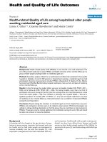
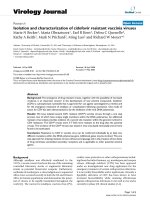
The influence of temperature has been studied for a
constant R =0.15(P
SiH4
= 55 mTo rr). Figure 1 show s
the SEM images of the NW gr own for 40 min at tem-
peratures varying from 325 to 450°C. As one can see, at
high temperatures, the uncatalyzed growth becomes too
important and inhibits the growth of NW above 400°C,
whereas temperatures below 350°C lead to a very slow
growth (poor density and small length). As the process
windowforSiGeNWseemstobeshallow,thegrowth
temperature for the rest of the study will be restricted
between 350 and 400°C.
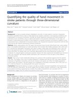
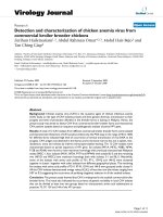
To change the Ge compositio n of the NW, the gas
ratio R is varied at a constant temperature of 375°C.
Figure 2 shows NW grown with R =0.15andR =0.09
and their respective Raman spectra. It was observed
Potié et al. Nanoscale Research Letters 2011, 6:187
/>Page 2 of 9
that the NW diameters vary from 20 to 60 nm, what-
ever be the growth conditions. The growth speed
increases linearly from 15 to 75 nm min
-1
when R
decreases from 0.15 to 0.048. This increase can be
imputed to the increase of the SiH
4
partial pressure
and thus of the silane deposition rate. DRX and
Raman measurements revealed that the Ge concentra-
tion (x)oftheSi
1-x
Ge
x
NW has been successfully var-
iedfrom0.2to0.46withR varying from 0.048 to 0.15,
respectively (Fig ure 2d).
Finally, the Ge concentration as a function of the tem-
perature (350, 375, 400°C) has been studied for R = 0.09
and 0.15 (P
SiH4
= 55 and 100 mTorr). The alloy compo-
sition shows little variation according t o growth tem-
perature for R =0.09.ForR = 0.15, it reaches 0.52 at
350°C, compared to 0.46 at 375 and 400°C. It is known
that activation energy for the decomposition is larger for
silane than for germane [16]. The increase in Ge com-
position has already been observed [30], which could be
explained by a lessened decomposition of the silane at
Figure 1 SEM images of Au-catalyzed SiGe NW grown for 40 min at various temperatures with R =0.15. S traight NW growth with a
good density occurs between 350 and 400°C. For higher temperatures, 2D growth becomes too important thus decreasing NW density. At T =
325°C, the temperature seems too low to get a satisfying density. The scale bars are 400 nm.
Figure 2 SEM images, Raman spectra and Ge fraction of SiGe NW. SEM images of SiGe NW grown during 40 min at 375°C with (a) R = 0.15
and (b) R = 0.09. (c) Raman spectra collected from samples (a,b). Arrows are pointing at the Si-Si peaks in SiGe used for calculating the Ge
fraction. The inset highlights the peaks’ shift between two different compositions (Raman shift = 488 cm
-1
for R = 0.15 and 499 cm
-1
for R =
0.09). (d) Representation of the Ge composition of the SiGe NW as a function of R.
Potié et al. Nanoscale Research Letters 2011, 6:187
/>Page 3 of 9
low temperature whereas germane decomposition is not
affected.
Silicide catalyst for Si NW growth
In the next section, it will be shown that silicon NW
can be grown by CVD using fully CMOS-compatible
catalysts: PtSi, Pd
2
Si, and NiSi. These silicides are cho-
sen because they are already present in the CMOS fabri-
cation processes. Silicon NW have been grown on Si
(100) by CVD using SiH
4
as the silicon gas precursor,
and H
2
as the carrier gas. The growth temperature var-
ied between 500 and 800°C and growths were carried
out with or without gaseous hydrochlori c acid (HCl).
The total pressure is maintained at 15 Torr unless
otherwise stated.
PtSi catalyst
PtSi islands, used as the catalys t [20], have been synthe-
sized according to the now described method. Before
NW growth, the (100)-Si substrate has been covered
with a thin (few nanometres) Pt layer obtained by physi-
cal vapor deposition. PtSi was formed by thermal
annealing under inert a tmosphere at high temperature,
and unreacted Pt was removed chemically after the
annealing step. The sample wa s then transferred from
the silicide furnace into the CVD reactor after an HF-
last cleaning step. Annealing is then adjusted to obtain
particles <100 nm. For instance, mean size is 45 nm dia-
meter by 5 nm height. XRD measurements after anneal-
ing show that the islands are crystalline PtSi with two
main growth directions [101] and [200].
After island’s formation, SiH
4
in H
2
is introduced into
the deposition chamber and the growth is studied as a
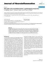
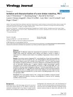
function of the temperature. As one can see in Figure 3,
the NW grown at low temperature have a constant dia-
meter along their length whereas growth at highe r tem-
peratures results in highly tapered NW. This effect
could b e explained by uncatalyzed growth on the side-
walls of the NW. The vertical growth rate was estimated
at 190 nm min
-1
, and the la teral growth rate at 6 nm
min
-1
(T = 700°C; silane partial pressure P
SiH4
=60
mTorr). Another explanat ion would be the incorpora-
tion of the catalyst into the NW resulting in a diminu-
tion of its diameter during growth. This phenomenon
might not be predominant because the diameter of the
NW tip is the same as the initial catalyst island (45 nm).
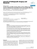
Since the temperatures investigated are less than the
PtSi/Si e utectic temperature (979°C), NW are expected
to grow via the vapour-solid-solid (VSS) mechanism.
During th e VSS growth, the catalyst remains solid at the
topoftheNWandenhancestheadsorptionand
decomposition of the precursor. Figure 4 shows a TEM
image of the PtSi catalyst at the top of a Si NW, which
supports the previous hypothesis. Indeed, the catalyst
particle is clearly crystalline. Unlike Au, PtSi does not
form a spherical cap on the top of the NW. It remains
strongly faceted or flat suggesting that catalyst does not
melt - otherwise, surface tension force s would favor a
spherical profile.
It is possible to grow silicon NW with PtSi between
500 and 800°C but uncatalyzed deposition rate at such
temperatures becomes a serious issue responsible for
the grow th of a thick lay er and for an important tape r-
ing of the NW.
To improve the growth selectivity, HCl gas is intro-
duced into the deposition chamber along with SiH
4
.
Figure 5 shows four NW samples grown without HCl
and with three different HCl partial pressures (P
HCl
=
40, 100, and 160 mTorr). The NW are more or le ss
cone shaped, and the mean aperture angle (formed by
the sidewalls of the NW) has been measured on each
sample. The mean aperture angle decreases from 14.4°
without HCl to 2.7° with P
HCl
= 160 mTorr. The aper-
ture a ngle is a measurement of the tape ring of th e
NW. One can see that the tapering effect is reduced
when P
HCl
increases, which is most probably due to a
Cl surface coverage that inhibits the Si deposition on
the sidewalls [31].
Figure 3 SEM images of PtSi-catalyzed Si NW grown for 30 min at various temperatures: (a) 500°C, (b) 700°C, (c) 800°C. P
SiH4
is held constant at
60 mTorr. The NW grown at 700 and 800°C show a tapered shape, whereas the diameter of the NW grown at 500°C is constant (45 nm).
Potié et al. Nanoscale Research Letters 2011, 6:187
/>Page 4 of 9
10 nm
5 nm
Figure 4 TEM image of a silicon NW (T = 800°C, P
SiH4
=60mTorr,P
HCl
= 60 mTorr, 30 min) with PtSi catalyst at the top.Theimage
shows a clearly faceted catalyst, suggesting that it remains solid during growth.
Figure 5 SEM images of PtSi-catalyzed Si NW grown at 800°C for 10 min with different HCl partial pressures: (a) no HCl, (b) P
HCl
=40,
(c) P
HCl
= 100, (d) P
HCl
= 160 mtorr. Mean aperture angles (A) have been measured at the tip of the NW for each sample: (a) A = 14.4°, (b) A =
6.6°, (c) A = 3.4°, and (d) A = 2.7°. The aperture angle decreases when P
HCl
increases, which implies that the tapering effect is considerably
reduced using gaseous HCl.
Potié et al. Nanoscale Research Letters 2011, 6:187
/>Page 5 of 9
NiSi catalyst
NiSi islands have also been used to catalyze the growth
of Si NW. The islands formation method and the
experimental protocol are the same as for PtSi. XRD
measurements after annealing of the NiSi thin la yer
show that the islands are orthorhombic NiSi.
As for PtSi-catalyzed NW, the influence of P
HCl
and
temperature on the NiSi-catalyzed NW morphology has
been studied. First, P
HCl
hasbeenvariedfrom0to160
mTorr, P
SiH4
, with temperature and deposition time
being held constant. Figure 6 shows SEM image s of the
NW. As one can see, the length and density of the NW
increase with P
HCl
.FromP
HCl
= 100 mTorr, straight
NW can be observed.
Second, temperature has been varied from 500 to 800°
C, at constant HCl and silane partial pressures (respec-
tively, 160 and 100 mTorr) and fixed deposition time
(results not shown). It is observed that NW growth
occurs from 600°C, and the length and density of the
NW increase with the temperature. Straight NW can be
observed from 700°C.
Pd
2
Si catalyst
Finally, the growth of Si NW using Pd
x
Si
y
island cata-
lysts is reported. The catalyst islands have been formed
in the same fashion as presented above, and the experi-
mental protocol remains identical.
The effect of temperature on the NW growth with a
high P
HCl
/P
SiH4
ratio (P
HCl
/P
SiH4
= 3.3) was investigated.
Figure 7 shows NW grown at 600, 700, and 800°C. The
NW growth occurs from 700°C and the density of
straight NW increases with the temperature, as well as
the tapering effect. Another NW growth has been car-
ried out at lower pressure, for a comparable P
HCl
/P
SiH4
ratio, but at lower HCl and SiH
4
partial pressures. As
can be seen in Figure 7d, the low total pressure com-
bine d with the high P
HCl
/P
SiH4
ratio allows avoiding the
tapering of the NW and keeping high density and
length.
The SEM images of the catalyst (Figure 7d inset) sug-
gest that it remains solid during growth. Indeed, the
cylindrical-faceted shape is completely different from
the semi-spherical shape typical of Au catalysts af ter a
VLS growth. XRD diffraction measurements performed
after the NW growth show that the catalyst particle at
the NW tip are hexagonal Pd
2
Si. As expected accor ding
to the SEM images, there are no preferential d irections
for the NW growth.
It has been seen that the use of alternative catalysts
such as Pt, Ni, and Pd silicides for the growth of Si NW
requires high temperatures. Indeed, the growth occurs
through VSS process which consumes much more
energy than VLS, mainly because of the diffusion
through or at the surfac e of a solid catalyst. Worki ng at
temperatures above 700°C implies an important uncata-
lyzed growth rate. It has been shown that this uncata-
lyzed growth can considerably be lowered by using
gaseous HCl allowing the growth of less- or non-tapered
NW.Moreover,thepresenceofHClinthegasphase
increases the NW vertical growth rate. This could be
explained by an increased probability of silane mole-
cules’ decomposition on the catalyst because of an
important Cl coverage of the surface. The possibilities of
interactions between HCl and catalysts leading to an
Figure 6 SEM images of NiSi-catalyzed NW grown at 800°C for 10 min with different HCl partial pressures: (a) no HCl, (b) P
HCl
= 40, (c)
P
HCl
= 100, (d) P
HCl
= 160 mTorr. The lengths of straight NW are 4 μm for (c) and 8 μm for (d).
Potié et al. Nanoscale Research Letters 2011, 6:187
/>Page 6 of 9
increase of the NW growth rate are not rejected, but
this would require a more thorough study.
Mechanical characterization
Among the numerous NW’s potential applications, elec-
tromechanical systems have attracted an increasing
interest for the past few years [27]. The manipulation
and e xploitation of NW for such device requires accu-
rate knowledge of their mechanical properties at the sin-
gle object level. An AFM multipoint-bending protocol
allowing as-grown single NW characterization has been
developed by Gordon et al. [32]. It consists in measuring
the deflection of an AFM cantilever while performing
approach-retract curves at various positions along the
length of a cantilevered NW. This approach allows the
measurement of single NW’s Young modulus and spring
constant , and al levi ates uncertai ntie s inherent in singl e
point measurement. This AFM-based mechanical testing
has been carried out on Si and GaN NW grow n with
Au catalyst or without catalyst, respectively.
Cantilevered NW are imaged in tapping mode and
approach-retract cycles are performed at different loca-
tions along the NW length (Figure 8). During these
cycles, the NW is deformed by the AFM tip, deflection
of which is recorded as an i ndirect measurement of the
actual NW deflection. The force-di stance curves repre-
sent the force applied by the tip (f
tip
) as a function of
the z-axis piezo movements. Owing to theses curves, it
is possible to calculate the NW spring constant at each
measurement location. The NW Young’ s modulus can
be obtained from the differential equation which
describes w(x), the NW deflection along its length as a
function of f, and the force applied at x = a, in the limit
of small deflections.
EI
dw
dx
fa x
2
2
⎛
⎝
⎜
⎜
⎞
⎠
⎟
⎟
=−()
(1)
where E is the Young ’s modulus, and I = πr
4
/4 is the
moment of inertia.
A stress-strain relation, w here an effecti ve wire spring
constant (k
wire
) can be defined, is given by solving Equa-
tion (1) using appropriate boundary conditions:
f
rE
a
wk w=
⎛
⎝
⎜
⎜
⎞
⎠
⎟
⎟
=
3
4
4
3
wire
(2)
Therefore,
ka
rE
wire
()
=
⎛
⎝
⎜
⎜
⎞
⎠
⎟
⎟
−
−
13
4
13
3
4
/
/
(3)
With the radius of the NW r being deducted from the tap-
ing mode scan of the NW, a linear fit of k
wire
-1/3
,asafunc-
tion of the forcing location a, allows the calculation of E.
Si NW grown along the (111) direction have been
tested (results not shown). As expected [32], the
Figure 7 SEM images of PdSi-catalyzed NW. (a-c) are grown at P
tot
= 15 Torr, and a ratio P
HCl
/P
SiH4
= 3.3 (200 mTorr/60 mTorr) for 10 min at
different temperatures: (a) T = 600°C, (b) T = 700°C, (c) T = 800°C. NW shown on (d) are grown at P
tot
= 3 Torr, and at a ratio P
HCl
/P
SiH4
= 4 for
15 min at 800°C. In this condition, there is no tapering of the NW. The inset in Figure 4d shows a SEM image of the catalyst after growth. The
cylindrical-faceted shape is typical of VSS growth.
Potié et al. Nanoscale Research Letters 2011, 6:187
/>Page 7 of 9
measure d Young’s moduli are comparable to the bulk Si
young modulus along the (111) direction. Figure 9
shows the Young modulus of GaN NW with r ranging
from 100 to 300 nm determin ed according to th is
method. GaN NW grow along the c-axis ([0001] direc-
tion) [33], and the doted line on the graph represents
the bulk’sYoung’s modulus along the same direction.
As one can see, E tends to decrease when the radius
increases and becomes much lower than the bulk modu-
lus above r = 150 nm. The same behavior has already
been reported for GaN [34] and for ZnO NW [35].
A possible explanation could be a diminution of the
defect inside the crystal with the diminution o f the dia-
meter. As can be seen in ref [33], the section of GaN
NW can be irregular from one NW to another which
could explain the wide dispersion of t he Young’smod-
uli. Moreover, the NW’ s cross section becomes more
and more i rregular, and the crystalline quality decreases
as the NW diameter inc reases [33]. This could explain
such a decrease of the GaN NW’s Young’s moduli when
the NW diameters increase. This aspect constitutes the
main limit of this method; this is why NW with a
regular cylindrical diameter are required to obtain reli-
able results.
Conclusion
This article reviewed different metal-mediated methods
to synthesize Si and SiGe NW. First, gold-assisted synth-
esis of SiGe NW from 350 to 400°C o n Si(111) sub-
strates has been presented. The possibility to obtain a
wide range of composition (0 to 50% Ge in SiGe) by
varying the gas flow ratio was shown. Second, the
growth of silicon NW with silicides catalysts, such as
PtSi, NiSi, and Pd
2
Si was reported. Those catalysts pre-
sent an altern ative to gol d for the growth of N W with
optimized electrical properties. The NW are grown
through the VSS process which requires working at high
temperatures. The uncatalyzed growth rate, classically
important under these conditions, is inhibited by using
gaseous HCl. It allows Cl s urface coverage that impedes
the precursor adsorption and decomposition thus pre-
venting the NW to be tapered. Finally, AFM-based
mechanical characterization of single GaN NW is pre-
sented. It is shown that the apparent NW ’sYoung’s
Figure 8 Single NW mechanical characterization. (a) AFM tapping-mode image of a GaN NW. (b) Principle of mechanical measurement on a
single NW where w is the NW deflection when a force f is applied at a position a. The cantilever deflection is measured as an indirect
measurement of w.
Figure 9 Young’s moduli of GaN NW as a function of the NW radius. The error bar is estimated according to the following formula: ΔE/E =
3|Δa/a|+4|Δr/r|. The dashed line represents the GaN bulk modulus in the [0001] direction.
Potié et al. Nanoscale Research Letters 2011, 6:187
/>Page 8 of 9
modulus seems to increase when the NW’ s diameter
decreases. This could be explained by a reduction of the
defect in small diameter NW and by an irregular cross
section of the NW when the diameter increases.
Abbreviations
CVD: chemical vapor deposition; NW: nanowires; SC: semiconductor; SEM:
scanning electron microscopy; TEM: transmission electron microscopy; XRD:
X-ray diffraction.
Author details
1
LTM/CNRS-CEA-LETI, 17, rue des martyrs, 38054 Grenoble, France.
2
CEA/
INAC/SiNaPS, 17, rue des martyrs, 38054 Grenoble, France.
3
IMEP-LAHC,
Grenoble Institute of Technology, MINATEC, BP 257, 3 parvis Louis NEEL
38016 Grenoble, France.
4
LMGP, CNRS, Grenoble Institue of Technology, 3
parvis Louis Néel, 38016 Grenoble, France.
Authors’ contributions
AP carried out the SiGe NW growth,SEM characterization, analysis and
interpretation of the data and drafted the manuscript. TB conceived the
study and carried out its coordination,the analysis and interpretation of the
data, participated to the growth of NW, and revised the manuscript. FD
carried out the growth of Si NW, SEM characterization, analysis and
interpretation of the results. PG, FO, participated to the growth of Si and
SiGe NW. BS and GR carried out the substrates preparation prior to growths
and participated to the SEM characterization of the NW. LLR carried out the
TEM analysis, MK carried out the AFM measurements, LM participated to the
revision of the manuscript, JK carried out the Raman measurements, HR
carried out the XRD measurements. All authors read and approved the final
manuscript.
Competing interests
The authors declare that they have no competing interests.
Received: 20 September 2010 Accepted: 1 March 2011
Published: 1 March 2011
References
1. Thelander C, Mårtensson T, Björk MT, Ohlsson BJ, Larsson MW,
Wallenberg LR, Samuelson L: Single electron transistor in heterostructure
nanowires. Appl Phys Lett 2003, 83:2052.
2. Cui Y, Zhong Z, Wang D, Wang WU, Lieber CM: High performance silicon
nanowire field effect transistors. Nano Lett 2003, 3:149.
3. Cui Y, Lieber CM: Functional nanoscale electronic devices assembled
using silicon nanowire building blocks. Science 2001, 291:851.
4. Duan X, Huang Y, Cui Y, Wang J, Lieber CM: Indium phosphide nanowires
as building block for nanoscale electronic and optoelectronic devices.
Nature 2001, 409:66.
5. Qian F, Gradečak S, Li Y, Wen CY, Lieber CM: Core/multishell nanowire
heterostructures as multicolor, high efficiency light-emitting diodes.
Nano Lett 2005, 5:2287.
6. Duan X, Huang Y, Agarwal R, Lieber CM: Single-nanowire electrically
driven lasers. Nature 2003, 421:241.
7. Kamins TI, Sharma S, Yasseri AA, Li Z, Straznicky J: Metal-catalyzed,
bridging nanowires as vapour sensors and concept for their use in a
sensor system. Nanotechnology 2006, 17:S291.
8. Cui Y, Wei Q, Park H, Lieber CM: Nanowire nanosensor fir highly sensitive
and selective detection of biological and chemical species. Science 2001,
293:1289.
9. Law M, Greene LE, Johnson JC, Saykally R, Yang P: Nanowire dye-
sensitized solar cells. Nat Mater 2005, 4:455.
10. Baxter JB, Aydil ES: Nanowire-based dye-sensitized solar cells. Appl Phys
Lett 2005, 86:053114.
11. Law M, Greene LE, Radenovic A, Kuykendall T, Liphard J, Yang P: ZnO-
Al2O3 and ZnO-TiO2 core-shell nanowire dye-sensitized solar cells. J
Phys Chem B 2006, 110:22652.
12. Dornel E, Ernst T, Barbé SC, Hartmann JM, Delaye V, Aussenac F, Vizioz C,
Borel S, Maffini-Alvaro V, Isheden C, Foucher J: Hydrogen annealing of
arrays of planar and vertically stacked Si nanowires. Appl Phys Lett 2007,
91:233502.
13. Wagner RS, Ellis WC: Vapor-Liquid-Solid mechanism of single crystal
growth. Appl Phys Lett 1964, 4:89.
14. Haller EE: Germanium: From its discovery to SiGe devices. Mater Sci
Semicond Process 2006,
9:408-422.
15. Berbezier I, Ronda A: SiGe nanostructures. Surf Sci Rep 2009, 64:47-98.
16. Lew KK, Pan L, Dickey EC, Redwing JM: Vapor-Liquid-Solid growth of
silicon-germanium nanowires. Adv Mater 2003, 15:2073-2076.
17. Kim CJ, Yang JE, Lee HS, Jang HM, Jo MH: Fabrication of Si1-xGex alloy
nanowire field effect transistor. Appl Phys Lett 2007, 91:033104.
18. Kawashima T, Imamura G, Fujii M, Hayashi S, Saitoh T, Komori K: Raman
and electron microscopic studies of Si1-xGex alloy nanowires grown by
chemical vapor deposition. J Appl Phys 2007, 102:124307.
19. Whang SJ, Lee SJ, Yang WF, Cho BJ, Kwong DL: Study on the synthesis of
high quality single crystalline Si1-xGex nanowire and its transport
properties. Appl Phys Lett 2007, 91:072105.
20. Baron T, Gordon M, Dhalluin F, Ternon C, Ferret P, Gentile P: Si nanowire
growth and characterization using a microelectronics-compatible
catalyst: PtSi. Appl Phys Lett 2006, 89:233111.
21. Wang Y, Schmidt V, Senz S, Gösele U: Apitaxial growth of silicon
nanowires using an aluminium catalyst. Nat Nanotechnol 2006, 1:186-189.
22. Wen CY, Reuter MC, Tersoff J, Stach EA, Ross FM: Structure, growth
kinetics, and ledge flow during Vapor-Liquid-Solid growth of copper-
catalyzed silicon nanowires. Nano Lett 2010, 10:514-519.
23. Kamins TI, Williams RS, Basile DP, Hesjedal T, Harris JS: Ti-catalyzed Si
nanowires by chemical vapor deposition: Microscopy and growth
mechanisms. J Appl Phys 2001, 89:1008-1016.
24. Hofmann S, Sharma R, Wirth CT, Cervantes-Sodi F, Ducati C, Kasama T,
Dunin-Borkowski RE, Drucker J, Bennett P, Robertson J: Ledge-flow-
controlled catalyst interface dynamics during Si nanowire growth. Nat
Mater 2008, 7:372-375.
25. Lensch-Falk JL, Hemesath ER, Perea DE, Lauhon JL: Alternative catalysts for
VSS growth of silicon and germanium nanowires. J Mater Chem 2009,
19:849-857.
26. Zhang ZY, Wu XL, Yang LW, Huang GS, Siu GG, Chu PK: Catalytic growth
of α-FeSi2 and silicon nanowires. J Cryst Growth 2005, 280:286-291.
27. Husain A, Hone J, Postma HWCh, Huang XMH, Drake T, Barbic M, Scherer A,
Roukes ML: Nanowire-based very-high-frequency electromechanical
resonator. Appl Phys Lett 2003, 83:1240.
28. Takeda S, Fujii H, Kawakita Y, Tahara S, Nakashima S, Kohara S, Itou M:
Structure of eutectic alloys of Au with Si and Ge. J Alloys Compd
2008,
422:149-153.
29. Alonso MI, Winer K: Raman spectra of c-Si1-xGex alloys. Phys Rev B 1989,
39:10056.
30. Lew KK, Pan L, Dickey EC, Redwing JM: Effect of growth conditions on the
composition and structure of Si1-xGex nanowires grown by Vapor-
Liquid-Solid growth. J Mater Res 2008, 21:2876.
31. Oehler F, Gentile P, Baron T, Ferret P: The effects of HCl on silicon
nanowire growth: surface chlorination and existence of a ‘diffusion-
limited minimum diameter’. Nanotechnology 2009, 20:475307.
32. Gordon M, Baron T, Dhalluin F, Gentile P, Ferret P: Size effects in
mechanical deformation and fracture of cantilevered silicon nanowires.
Nano Lett 2009, 9:525-529.
33. Koester R, Hwang JS, Durand C, Le Si Dang D, Eymery J: Self-assembled
growth of catalyst free GaN wires by metal-organic vapour phase
epitaxy. Nanotechnology 2010, 21:015602.
34. Chen Y, Stevenson I, Pouy R, Wang L, MCIlroy DN, Pounds T, Grant
Norton M, Eric Aston D: Mechanical elasticity of vapour-liquid-solid
grown GaN nanowires. Nanotechnology 2007, 18:135708.
35. Chen CQ, Shi Y, Zhang YS, Zhu J, Yan YJ: Size dependence of Young’s
modulus in ZnO nanowires. Phys Rev Lett 2006, 96:075505.
doi:10.1186/1556-276X-6-187
Cite this article as: Potié et al.: Growth and characterization of gold
catalyzed SiGe nanowires and alternative metal-catalyzed Si nanowir es.
Nanoscale Research Letters 2011 6:187.
Potié et al. Nanoscale Research Letters 2011, 6:187
/>Page 9 of 9