Báo cáo hóa học: " Research Article Performance Evaluation of Uplink Delay-Tolerant Packet Service in IEEE 802.16-Based Networks" potx
Bạn đang xem bản rút gọn của tài liệu. Xem và tải ngay bản đầy đủ của tài liệu tại đây (912.78 KB, 12 trang )
Hindawi Publishing Corporation
EURASIP Journal on Wireless Communications and Networking
Volume 2011, Article ID 549492, 12 pages
doi:10.1155/2011/549492
Research Article
Performance Evaluation of Uplink Delay-Tolerant
Packet Service in IEEE 802.16-Based Networks
Zsolt Saffer,
1
Sergey Andreev,
2
and Yevgeni Koucheryavy
2
1
Department of Telecommunications, Budapest University of Technology and Economics (BUTE),
Magyar tud
´
osok k
¨
or
´
utja 2, 1117 Budapest, Hungary
2
Department of Communications Engineering, Tampere University of Technology (TUT),
Korkeakoulunkatu 10, 33720 Tampere, Finland
Correspondence should be addressed to Zsolt Saffer, saff
Received 15 November 2010; Accepted 11 February 2011
Academic Editor: Boris Bellalta
Copyright © 2011 Zsolt Saffer et al. This is an open access article distributed under the Creative Commons Attribution License,
which permits unrestricted use, distribution, and reproduction in any medium, provided the original work is properly cited.
We provide an analytical model for efficient dynamic capacity allocation in IEEE 802.16 wireless metropolitan area network,
where the nonreal-time traffic can utilize the bandwidth unused by the real-time traffic. We investigate the uplink delay of the
nrtPS service flow as a function of the capacity allocations for the rtPS (ertPS) and UGS service flows. Unicast polling is applied
for the bandwidth reservation of the nrtPS and rtPS (ertPS) packets. Our analysis accounts for both reservation and scheduling
delay components. The nrtPS packets arrive according to Poisson process. The model enables asymmetric capacity allocation, as
well as asymmetric nrtPS traffic arrival flows. The analytical model is applied for investigating the influence of the real-time traffic
on the delay of the nrtPS service flow. We discuss also the determination of several traffic parameters under different constraints,
which have potential applications in network control.
1. Introduction
IEEE 802.16 standards family defines an air interface for
Broadband Wireless Access (BWA) system. As the result
of a recent revision, the contemporary core standard IEEE
802.16-2009 [1] consolidates the IEEE 802.16-2004 standard
with several amendments. According to [2], this wireless
interface is recommended for Wireless Metropolitan Area
Networks (WMANs). The high-speed air interface specified
by the IEEE 802.16 standards family enables multimedia ser-
vices and provides support for several traffictypestoensure
the wide range of Quality-of-Service (QoS) requirements of
end users.
The standardization of metropolitan-scale wireless access
is an ongoing activity performed by the IEEE 802.16 Working
Group for BWA with the support of WiMAX Forum [3]. The
uplink data packet scheduler, which is out of scope of the
IEEE 802.16-2009 standard, has a major impact on ensuring
QoS requirements of the end users. As a consequence,
numerous research papers deal with the problem of schedul-
ing, like [4–6], in which various frameworks are built and
analyzed to guarantee a specified level of QoS. For instance,
the work in [7]proposedanefficient QoS architecture, based
on priority scheduling and dynamic bandwidth allocation.
In [8], authors compare and contrast the performance
of various reservation schemes in the framework of the
simplified model. For a good summary on QoS in the context
of IEEE 802.16, we refer to the online paper [9].
The majority of the analytical works in the literature
do not account for both the reservation and the scheduling
components of the delay. The importance of accounting for
both components to evaluate the overall delay of access-
control systems was emphasized by an early fundamental
theoretical work by Rubin [10], as well as by our previous
papers [11, 12]. For a more practical approach, we refer to
[13], in which the realistic performance measures of IEEE
802.16 system are considered by various techniques. In [13,
14], the overall system delay is approximated and verified. In
our previous work [15], we established an analytical model
for the exact overall delay of the nrtPS service flow with
unicast polling in the IEEE 802.16 system. Other polling
techniques were studied in [16].
2 EURASIP Journal on Wireless Communications and Networking
VoIP
VoD
`
Subscriber station (SS)
Subscriber station (SS)
IP/ATM network
LAN LAN
`
VoIP
VoD
Base station (BS)
Subscriber station (SS)
Figure 1: IEEE 802.16 general architecture.
In this paper, we continue the works in [14, 15, 17]
by extending the analytical model to perform an efficient
dynamic capacity allocation, in which the nonreal-time
(delay-tolerant) traffic of each Subscriber Station (SS) can
utilize a portion of the spare bandwidth remaining after
the capacity allocation for the real-time (delay-critical)
traffic flows at every SS. Thus, the model incorporates the
effect of the capacity allocation for the real-time polling
service (rtPS), extended real-time polling service (ertPS), and
unsolicited grant service (UGS) flows on the overall delay of
the non real-time polling service (nrtPS) flow. The variable
nrtPS capacity of the individual SS is allowed to depend
on real-time capacities of every SS. The nrtPS capacity
of each SS is determined by means of priorities among
them for their non real-time traffic flows. This prioritization
allows the realization of different service levels—probably for
different prices—in terms of capacity utilization for non real-
time traffic. This ensures a guaranteed portion of the total
available nrtPS capacity for each SS also in the case when non
real-time traffic is saturated at one or more other SSs. The
analytical approach leads to a queueing model with batch
packet service. The expression for the mean packet delay is
given in terms of model probabilities, which are computed
from the equilibrium distribution of a properly identified
embedded Markov chain.
The analytical model is applied to the performance
evaluation of the uplink nrtPS traffic in the IEEE 802.16-
based network. Beside providing numerical examples, we
study the modeled influence of the real-time traffic on the
delay of the nrtPS service flow. We discuss how to take into
accountanupperboundonmeandelayofthenrtPSservice
flow at the SSs in determining the maximum of the sum
of the real-time capacities at every SS. Finally, we introduce
a cost model, which takes into account the QoS on delay
constraint and on the real-time capacity parameters. The
different aspects of this performance analysis have potential
applications in network control, since they facilitate the
setting of the capacity parameters to the requirements of the
actual application scenario.
The rest of the paper is structured as follows. Section 2
gives a brief summary of the channel allocation schemes in
IEEE 802.16. In Section 3, we provide the analytical model
including the details of the capacity allocation and the uplink
scheduling. The analysis of the queueing model follows in
Section 4. We determine the mean overall packet delay of
the nrtPS service flow in Section 5.InSection 6,wegive
numerical examples for the performance analysis. Finally the
conclusion in Section 7 closes the paper.
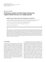
2. Channel Allocation Schemes in IEEE 802.16
The mandatory centralized point-to-multipoint (PMP) IEEE
802.16 architecture (see Figure 1) comprises a Base Station
(BS) and one or more SSs in its vicinity. The packets are
exchanged between BS and SSs via separate channels. The
downlink (DL) channel is used for the traffic from the BS
to the SSs, and the uplink (UL) channel is used in the reverse
direction.
The standard defines two mechanisms of multiplexing
the DL and the UL channels: Time Division Duplex (TDD)
and Frequency Division Duplex (FDD). In FDD mode, the
DL and the UL channels are assigned to different subband
frequencies. In TDD mode, the channels are differentiated
by assigning different time intervals to them, that is, MAC
frame is divided into DL and UL parts. The border between
these parts may change dynamically depending on the SSs
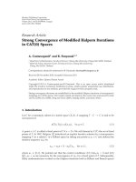
bandwidth requirements. The SSs access the UL channel
by means of Time-Division Multiple Access (TDMA). The
structure of the MAC frame in TDD/TDMA mode is shown
in Figure 2.
The current IEEE 802.16-2009 standard, as well as its
future version IEEE 802.16 m [18], specifies Orthogonal
EURASIP Journal on Wireless Communications and Networking 3
Frame
UL-MAP indicates the starting time slot of each uplink burst
UL-MAP
DL-MAP
Preamble
Uplink (UL) subframeDownlink (DL) subframe
Reservation
interval (RI)
Bandwidth request
(BW-req)
.
.
.
SS
1
transmission
interval
SS
N
transmission
interval
Figure 2: IEEE 802.16 MAC frame structure in TDD/TDMA mode.
Frequency-Division Multiple Access (OFDMA) at the physi-
cal layer.
3. Analytical Model and Notations
In the considered model, all the five service flow types are
allowed at each SS (see Figure 3), each one with a dedicated
Connection ID (CID) and a Service Flow ID (SFID). For
UGS, rtPS, and ertPS packet service, the QoS guarantees
are ensured by means of the necessary capacity allocations.
The nrtPS and Best Effort (BE) service flows utilize spare
bandwidth, where the nrtPS service flow is prioritized over
the BE traffic. In the evaluation of the nrtPS packet service
delay, we account also for the effects of the UGS, rtPS, and
ertPS service flows.
3.1. Restrictions of the Model. We impose several limitations
on the IEEE 802.16 model.
(R.1) The operational mode is PMP, and TDD/TDMA
channel allocation scheme is used. Our TDD/TDMA
modelderivedinthispapercanbeappliedforboth
OFDMA-based versions (IEEE 802.16-2009 and IEEE
802.16 m).
(R.2) Only theuplink traffic is considered, as well as unicast
polling is used for nrtPS, rtPS, and ertPS services.
(R.3) The uplink packet scheduler at the BS keeps an
individual buffer for each SS to serve the nrtPS
packets.
(R.4) The BE traffic is assumed to be saturated.
(R.5) Piggybacking is not used.
3.2. General Model. There are N SSs and 1 BS in the system,
which together comprise N + 1 stations. Each SS maintains
separate buffers of infinite capacity for the uplink packets
of different service flows. The nrtPS packets arrive at SS i
according to the Poisson arrival process with arrival rate λ
i
for i = 1, , N. Hence, the overall nrtPS packet arrival rate
is λ
=
N
i
=1
λ
i
. We call the nrtPS packets arriving to SS i as
i-packets.
The arrival processes at the different SSs are mutually
independent. The packet length is fixed and equals η
−1
bit, which includes data information and the header with
packing/fragmentation overhead. The transmission rate of
each channel is β bps. Therefore, the transmission time of
adatapacketisτ
= (ηβ)
−1
. All time durations are measured
in seconds.
T
f
denotes the duration of each frame. While all the SSs
are allowed to transmit in the uplink of one frame, they
may be grouped by the reservation mechanism to reduce
the polling overhead [14, 19]. Accordingly, in one frame
only SSs belonging to one group are polled and are allowed
to send their bandwidth request (BW-Req) messages. Then,
the nonoverlapping groups are polled in consecutive frames.
P denotes the number of SSs in each group, and, hence,
the number of groups is L
= N/P. The same SSs group is
polled in every Lth frame. The minimal period between two
consecutive pollings of the same SSs group is called a polling
cycle. Thus, the length of a polling cycle is LT
f
. The SSs
grouping model is shown in Figure 4.
The duration of the DL and the UL sub-frames are T
d
and
T
u
,respectively.T
ri
stands for the duration of the reservation
interval, and T
ud
is the maximum available duration of the
uplink data transmission in a frame. Therefore, T
u
is given
by T
u
= T
ri
+ T
ud
.
The transmission time of a BW-Req is α.Hence,T
ri
= Pα
and T
ud
can be expressed as T
ud
= T
u
− Pα.
3.3. Capacity Allocation. As the packet transmission time is
fixed, we measure the capacity in the number of packets. Let
C
u
i
denote the fixed capacity assigned for SS i in a frame for
the uplink UGS trafficfori
= 1, , N. Similarly, R
i
stands
for the variable capacity assigned for SS i in a frame for the
uplink rtPS and ertPS transmissions together. The range of
the discrete-time random variable R
i
is, thus, given by
R
min
i
≤ R
i
≤ R
max
i
, i = 1, ,N.
(1)
Let H be the total remaining uplink capacity for the nrtPS
packet service of all the SSs after allocating the necessary
capacity for the above three real-time traffic flows. Thus, H
can be expressed as
H
=
T
ud
τ
−
N
i=1
C
u
i
−
N
i=1
R
i
.
(2)
Let 0
≤ ω
i
≤ 1 denote the fixed priority weight of SS i for
the nrtPS capacity allocation for i
= 1, , N. The variable
4 EURASIP Journal on Wireless Communications and Networking
Subscriber station (SS)
Applications
CID/SFID classification
UGS
Packet
scheduler
Data packet
Connection request
Data
traffic
rtPS
CID
CID
CID
CID
CID
CID
CID
CID
CID
CID
ertPS nrtPS BE
UL-MAP
BW-request
Connection response
Admission control
undefined by IEEE 802.16
Base station (BS)
Uplink packet scheduling
algorithm undefined by
IEEE 802.16
Figure 3: IEEE 802.16 QoS architecture.
Polling cycle = L frames
Transmission
intervals
Transmission
intervals
Transmission
intervals
DL
sub-
frame
RI SS
1
··· SS
N
DL RI SS
1
··· SS
N
··· DL RI SS
1
··· SS
N
P polling
slots
P polling
slots
P polling
slots
kth frame (k + 1)th frame (k + L)th frame
Figure 4: The SSs grouping model.
capacity available for SS i in a frame for the uplink nrtPS, H
i
,
is given by
H
i
=ω
i
H, i = 1, , N,
N
i=1
ω
i
= 1,
(3)
where
d stands for the integral part of d.Thus,H
i
is given
in the dependency of the total allocated capacity for the UGS,
rtPS, and ertPS services of all the SSs. Using (2)and(3)leads
to the following range of H
i
:
H
min
i
≤ H
i
≤ H
max
i
,where
H
min
i
=
⎢
⎢
⎢
⎣
ω
i
⎛
⎝
T
ud
τ
−
N
i=1
C
u
i
−
N
i=1
R
max
i
⎞
⎠
⎥
⎥
⎥
⎦
≥
1,
H
max
i
=
⎢
⎢
⎢
⎣
ω
i
⎛
⎝
T
ud
τ
−
N
i=1
C
u
i
−
N
i=1
R
min
i
⎞
⎠
⎥
⎥
⎥
⎦
, i = 1, ,N.
(4)
Expression (4) shows that the capacity available for
the nrtPS traffic is given by an upper-limited discrete-time
random variable, whose value is at least one. This ensures
that the nrtPS traffic can not be blocked by the UGS, rtPS,
and ertPS trafficflows.
Finally, the BE service flow utilizes the remaining capac-
ity, which is not used by the nrtPS traffic. This together with
the restriction (R.4) ensures an efficient capacity utilization,
in which the total available nonreal-time capacity (H)is
always utilized. The described capacity allocation scheme is
illustrated in Figure 5.
Summarizing, our general capacity allocation scheme
enables asymmetric capacity allocation for the UGS, rtPS,
and ertPS services, as well as asymmetric nrtPS trafficflows.
3.4. Model Assumptions. Let Y
i
denote the number of
actually transmitted nrtPS packets of SS i in a frame. In
statistical equilibrium, the mean number of transmitted
nrtPS packets equals the mean number of arriving nrtPS
packets per frame at each SS. This yields
E
[
Y
i
]
= λ
i
T
f
, i = 1, ,N.
(5)
The number of transmitted nrtPS packets is upper-
limited by the capacity available for them
Y
i
≤ H
i
, i = 1, ,N.
(6)
EURASIP Journal on Wireless Communications and Networking 5
DL
subframe
RI
UGS
traffic
(e)rtPS
traffic
nrtPS
(BE)
traffic
···
UGS
traffic
(e)rtPS
traffic
nrtPS (BE)
traffic
C
u
1
R
1
H
1
C
u
N
R
N
H
N
w
1
Hw
N
H
Figure 5: The capacity allocation scheme.
Below, we formulate the assumptions of our model.
(A.1) Using (5), (6), (3), and (2) implies that the following
relation holds for the arrival rate of each SS i below
the stability boundary:
λ
i
T
f
<E
⎡
⎣
⎢
⎢
⎢
⎣
ω
i
⎛
⎝
T
ud
τ
−
N
i=1
C
u
i
−
N
i=1
R
i
⎞
⎠
⎥
⎥
⎥
⎦
⎤
⎦
,
i
= 1, , N.
(7)
This relation ensures the stability of the model.
(A.2) The BS uplink scheduler processing delay is negligi-
ble.
(A.3) The channel propagation time is negligible.
(A.4) The transmission channels are error free.
3.5. Uplink Scheduling. ABW-ReqsentbytheSSi represents
the aggregated request for all nrtPS packets, which are
accumulated in its outgoing buffer during the last cycle,
that is, since the previous BW-Req sending. We leave the
process of bandwidth requesting for rtPS and ertPS packets
out of scope of this paper. Furthermore, we assume that
the BS knows the number of rtPS and ertPS packets at
each SS in every frame and thus it can take them into
account calculating the actual available capacity for the nrtPS
packets H
i
. We note that the actual uplink transmission
requirements represented by the rtPS and ertPS requests are
always granted, since they are below the available capacity.
The fixed priority weights assigned to the SSs enable
mutually independent uplink scheduling for the nrtPS
service flows of the individual SSs. Thus, for the service of the
aggregated BW-Req for the nrtPS packets, the BS maintains
an individual BS grant buffer with infinite capacity for each
SS. Let i-polling slot stands for the (((i
− 1) mod P)+1)th
polling slot within the reservation interval of the frame,
in which the group of SS i is polled. At the end of the i-
polling slot, the BS immediately processes the requests for
the nrtPS packets from SS i, if any, and serves the individual
BS grant buffer of SS i. We refer to the end of the i-polling
slot as i-reservation epoch. The BS grant buffer of SS i is
also served at the epochs following an i-reservation epoch
by T
f
,2T
f
, ,(L − 1)T
f
time. Hence, all these epochs,
including also the i-reser vation epochs,arecalledi-scheduling
epochs. The positions of the considered epochs are marked in
Figure 6.
Receiving a request for the nrtPS packets from SS i at an
i-reservation epoch, an individual BS grant is assigned to each
nrtPS data packet of that request, and then these BS grants
are placed into the corresponding individual BS grant buffer
of SS i according to their order in the request. Let the number
of the BS grants in the buffer of SS i be S
i
= 0,1, During
the service of the individual BS grant buffer of SS i at an i-
scheduling epoch, the BS takes the available BS grants from
that buffer up to the available capacity for the nrtPS service
flow of SS i (H
i
) and schedules them for transmission in the
UL-MAP of the following frame. Their number equals the
number of i-packets transmitted in the next frame, Y
i
.
Thus, the number of scheduled BS grants is given by
Y
i
= min
(
S
i
, H
i
)
,
(8)
where min(a, b) stands for the smallest value of the set (a, b).
An example of the BS uplink scheduling is illustrated in
Figure 7.
The features of the considered uplink scheduling process
can be summarized as follows.
(F.1) The capacity requirements of the UGS, rtPS, and
ertPS service flows are always satisfied.
(F.2) The capacity allocation enables priorities for the
nrtPS service flows (ω
i
at SS i for 1, , N). This
corresponds to a weighted round-robin scheduling
of the dynamically variable capacity, which remains
available after ensuring the service of the real-time
trafficflows.
(F.3) The scheduling mechanism ensures efficient capacity
utilization, since the remaining capacity not used by
the nrtPS traffic flow at each SS is filled the BE traffic
at this SS.
4. Queueing System Analysis
The individual polling slot for each SS in a polling cycle and
the independent uplink scheduling for the individual SSs
together imply that the statistical behavior of the BS grant
buffer of a particular SS is independent from the behavior of
those of the other SSs. Therefore, we model the stochastic
behavior of the BS grant buffer of a particular SS by an
individual queueing system.
In this queueing system, the BS grants arrive to the BS
grant buffer of SS i at i-reservation epochs and they are served
at i-scheduling epochs.
4.1. The Contents of the BS Grant Buffer at i-Reservation
Epochs. Let N
i
() be the number of BS grants in the BS grant
6 EURASIP Journal on Wireless Communications and Networking
T
f
i-scheduling epochs
i-reservation
epoch
(L
− 1)T
f
DL
sub-
frame
RI SS
1
··· SS
N
DL RI SS
1
··· SS
N
··· DL RI SS
1
··· SS
N
i polling
slots
k-th frame (k + 1)th frame (k + L
− 1)th frame
Figure 6: Characteristic epochs of uplink scheduling.
SS
i
Individual BS grants buffer
Ta gg ed p a cke t
arrival
UL-MAP forming
nrtPS packets
transmission
DL
BW-req for 2 packets
UGS
traffic
(e)rtPS traffic
(BE) traffic
DL
UGS
traffic
(e)rtPS
traffic
nrtPS traffic
(BE)
traffic
DL
Tagged packet overall delay
Figure 7: Example BS uplink scheduling for a single SS.
buffer of SS i at the th i-reservation epoch for >0. The
sequence
{N
i
(), >0} is an embedded Markov chain on
the state space
{0, 1, }.Let[Π
i
]
j,k
denote the probability of
transition from state j to state k of the Markov chain, and
it is the ( j, k)th element of the
∞×∞probability transition
matrix Π
i
.
Let H
(m)
i
be the accumulated available capacity for the
i-packets during m consecutiveframesform
= 0, , L.
The distribution of H
(m)
i
is given as the m-times convolution
of the distribution of H
i
for m = 1, , L. The definition
of H
(0)
i
implies that it takes the value 0 with probability 1.
It immediately follows that the minimum and maximum
values of H
(m)
i
are mH
min
i
and mH
max
i
,respectively.
Let us consider the transition from state j to state k in the
above defined Markov chain. The probability that the actual
accumulated available capacity for the i-packets during a
polling cycle is n equals P(H
(L)
i
= n). Assuming that j ≥ n
implies that the number of remaining BS grants in the BS
grant buffer of SS i after its services during a cycle is j
− n,
which implies that k
≥ j − n. Thus, on one hand, n ≥ j − k
must hold and, on the other hand, k
− j + ni-packet arrivals
occur during this transition. Hence, this case contributes to
[Π
i
]
j,k
with the probability
j
n= j−k
P
H
(L)
i
= n
λ
i
LT
f
k− j+n
k − j + n
!
e
−λ
i
LT
f
.
(9)
Now assuming that j +1
≤ n implies that all the j
BS grants are served during the cycle and, thus, ki-packet
arrivals occur during this transition. Thus, the contribution
of this case to [Π
i
]
j,k
is the probability
LH
max
i
n= j+1
P
H
(L)
i
= n
λ
i
LT
f
k
k!
e
−λ
i
LT
f
.
(10)
Taking also into account the lower and upper limits of
H
(L)
i
, the transition probability [Π
i
]
j,k
can be expressed as
[
Π
i
]
j,k
=
min
(
LH
max
i
,j
)
n=max
(
LH
min
i
,j−k
)
P
H
(L)
i
= n
×
λ
i
LT
f
k− j+n
k − j + n
!
e
−λ
i
LT
f
+
LH
max
i
n=max
(
LH
min
i
,j+1
)
× P
H
(L)
i
= n
λ
i
LT
f
k
k!
e
−λ
i
LT
f
, j, k ≥ 0,
(11)
where max(a, b) stands for the largest value of set (a, b).
Let [π
i
]
k
denote the equilibrium probability of the state
k in the Markov chain, and it is the (k)th element of the 1
×
∞
probability vector π
i
. Furthermore, let e be the column
vector having all elements equal to one.
Then, the equilibrium probabilities of the Markov chain
can be uniquely determined from the following system of
linear equations:
π
i
Π
i
= π
i
, π
i
e = 1.
(12)
EURASIP Journal on Wireless Communications and Networking 7
To keep the computation tractable, an upper limit K
i
>
H
min
i
is set on the states, which results in the finite number
of unknowns and equations in the system of linear equations.
An appropriate value of K
i
depends on the required precision
level, at which the probabilities [π
i
]
k
for k>K
i
can be
neglected. These probabilities, [π
i
]
k
for k>K
i
, are set to 0.
4.2. The Contents of the BS Grant Buffer at i-Scheduling
Epochs. Let [π
+
i
]
k
denote the probability that the number of
BS grants in the BS grant buffer of SS i at an arbitrarily chosen
i-scheduling epoch is exactly k, and it is the (k)th element
of the 1
× (K
i
+1)probabilityvectorπ
+
i
for k = 0, , K
i
.
The probability that an arbitrarily-chosen i-scheduling epoch
is the mth after the last i-reservation epoch is 1/L for m
=
0, , L− 1. Note that by definition the 0th i-scheduling epoch
after the last i-reservation epoch is that i-reservation epoch.
By definition, the time instant of handling the nrtPS
packet requests from SS i is the i-reservation event. Similarly,
by definition the instants of scheduling the BS grants in
the BS grant buffer of SS i are the i-scheduling events.The
positioning of the i-reservation epoch and the i-scheduling
epochs (observation epochs) relatively to the i-reservation and
i-scheduling events is shown in Figure 8.
At the mth i-scheduling epoch after the last i-reservation
epoch, the i-packets in the BS grant buffer of SS i are those
which remained after the last m services of the BS grant
buffer. Hence, the probability [π
+
i
]
k
can be established as
π
+
i
k
=
L−1
m=0
1
L
mH
max
i
n=mH
min
i
P
H
(m)
i
= n
[
π
i
]
n+k
,
0 <k
≤ K
i
,
π
+
i
0
=
L−1
m=0
1
L
mH
max
i
n=mH
min
i
P
H
(m)
i
= n
n
j=0
[
π
i
]
j
.
(13)
4.3. The Contents of the BS Grant Buffer at an Arbitrary Epoch.
At an arbitrary epoch between two consecutive i-scheduling
epochs, the BS grants in the BS grant buffer of SS i are those
which remained after the service of the BS grant buffer at the
last i-scheduling epoch. Hence, the probability of being exactly
k packets in the BS grant buffer of SS i at an arbitrary epoch,
p
k
,isgivenby
p
k
=
H
max
i
n=H
min
i
P
(
H
i
= n
)
π
+
i
n+k
,0<k≤ K
i
− H
min
i
,
p
0
=
H
max
i
n=H
min
i
P
(
H
i
= n
)
n
j=0
π
+
i
j
.
(14)
4.4. The Size of the Transmitted i-Packet Batch. Let us
consider the probability of transmitting exactly ni-packets
in a frame for 0
≤ n ≤ min(H
max
i
, K
i
). This can occur in two
cases. In the first one, the actual available capacity for the i-
packetsisexactlyn and there are at least n BS grants in the
BS grant buffer of SS i at i-scheduling epoch. The probability
of this case is
K
i
k=n
P
(
H
i
= n
)
π
+
i
k
.
(15)
In the other case, the number of BS grants in the BS
grant buffer of SS i at i-scheduling epoch is n, but the actual
available capacity for the i-packets, k, is greater than n. This
has the following probability:
H
max
i
k=n+1
P
(
H
i
= k
)
π
+
i
n
.
(16)
Taking also into account the lower limit of H
i
, the
probability of transmitting exactly n i-packets in a frame can
be expressed as
P
(
Y
i
= n
)
=
K
i
k=n
P
(
H
i
= n
)
π
+
i
k
+
H
max
i
k=max
(
H
min
i
,n+1
)
P
(
H
i
= k
)
π
+
i
n
,
0
≤ n ≤ min
H
max
i
, K
i
.
(17)
5. Overall Delay Analysis
5.1. Overall Delay Definition. We define the overall delay
(W
i
) of the tagged i-packet as the time interval spent from
its arrival into the outgoing buffer of SS i up to the end of its
successful transmission in the UL. It is composed of several
parts
W
i
= W
r
i
+ α + W
s
i
+ W
t
i
+ τ.
(18)
Here, W
r
i
is the reservation delay, which is defined as the
time interval from the i-packet arrival to SS i until the start
of sending a corresponding BW-Req to the BS. We define the
grant time of the tagged i-packet as the i-scheduling epoch in
the frame preceding the one, in which the tagged i-packet
is transmitted. W
s
i
is the scheduling delay, which is defined
as the time interval from the end of sending a BW-Req of
the tagged i-packet to its grant time. W
t
i
is the transmission
delay, which is defined as the time interval from the grant
time of the tagged i-packet to the start of its successful
transmission in the UL sub-frame.
5.2. Reservation Delay. Abandwidthrequestcanbesent
for the nrtPS packets from SS i in the i-polling slot of
every polling cycle. Thus, an arriving i-packet waits for the
reservation opportunity until the end of the current cycle,
and, hence, the mean reservation delay is given by
E
W
r
i
=
LT
f
2
.
(19)
8 EURASIP Journal on Wireless Communications and Networking
1-st i-scheduling
event
i-scheduling
event
2-nd i-scheduling
event
Lth i-scheduling
event
···
0th i-scheduling
epoch
1-st i-scheduling
epoch
(L − 1)-st i-scheduling
epoch
i-reservation
epoch
Observation epochs
Figure 8: Positions of the observation epochs within a polling cycle.
5.3. Scheduling Delay. The definition of the scheduling delay
implies that the scheduling delay of the tagged i-packet is
exactly the sojourn time of the BS grant assigned to the
tagged i-packet in the BS grant buffer of SS i. Consequently,
the mean scheduling delay can be determined by applying the
Little’s law on the mean number of i-packets in the BS grant
buffer of SS i at an arbitrary epoch. Taking also into account
the tractable computation of π
i
, the mean scheduling delay
can be expressed as
E
W
s
i
=
∞
k=1
kp
k
λ
i
∼
=
K
i
−H
min
i
k=1
kp
k
λ
i
.
(20)
5.4. Transmission Delay. The transmission delay is the sum
of the fixed time from the grant time of the tagged i-packet
to the start of transmission of the i-packets in the next frame
and the transmission times of the random number of i-
packets preceding the tagged i-packet. Let y
i
and y
(2)
i
be
the first two factorial moments of the number of i-packets
transmitted in a frame. The mean number of i-packets
preceding the tagged i-packet is y
(2)
i
/2y
i
(see [20]). Using it,
the definitions of the first two factorial moments and taking
into account the range of Y
i
, the mean transmission delay can
be expressed as
E
W
t
i
= T
f
− α
(((
i − 1
)
mod P
)
+1
)
+ Pα +
i
j=1
C
u
j
τ
+
i
j=1
E
R
j
τ +
i−1
j=1
y
j
τ +
y
(2)
i
2y
i
τ
= T
f
+ α
(
P −
((
i
− 1
)
mod P
)
− 1
)
+
i
j=1
C
u
j
τ
+
i
j=1
E
R
j
τ +
i−1
j=1
⎛
⎜
⎝
min
(
H
max
i
,K
i
)
k=1
P
Y
j
= k
k
⎞
⎟
⎠
τ
+
min(H
max
i
,K
i
)
k
=2
P
(
Y
i
= k
)
k
(
k − 1
)
2
min(H
max
i
,K
i
)
k
=1
P
(
Y
i
= k
)
k
τ.
(21)
5.5. Mean Overall Delay. Taking the mean of (18)and
substituting the expressions (19), (20), and (21), we obtain
the expression for the mean overall delay of the tagged i-
packet as
E
[
W
i
]
=
L +2
2
T
f
+
K
i
−H
min
i
k=1
kp
k
λ
i
+ α
(
P −
((
i
− 1
)
mod P
))
+ τ
+
⎡
⎢
⎣
i
j=1
C
u
j
+
i
j=1
E
R
j
+
i−1
j=1
⎛
⎜
⎝
min
(
H
max
i
,K
i
)
k=1
P
Y
j
= k
k
⎞
⎟
⎠
⎤
⎥
⎦
τ
+
min(H
max
i
,K
i
)
k
=2
P
(
Y
i
= k
)
k
(
k − 1
)
2
min(H
max
i
,K
i
)
k
=1
P
(
Y
i
= k
)
k
τ.
(22)
6. Performance Evaluation
In this section, we apply the derived analytical model to the
performance evaluation of the uplink nrtPS packet service in
the IEEE 802.16-2009 network.
6.1. Numerical Examples. Here, we provide numerical exam-
ples to assess the performance of the IEEE 802.16 uplink
nrtPS service flow evaluated with the considered analytical
model. In order to generate performance data, a simulation
program for IEEE 802.16-2009 MAC was developed. The
program is an event-driven simulator that accounts for the
discussed restrictions on the considered system model (see
Section 3).
In our simulations, we set the default values recom-
mended by WiMAX Forum [3] system evaluation method-
ology, which are also common values used in practice [21].
We assume a 10 MHz TDD system with 5 ms frame duration,
PUSC subchannelization mode, and a DL : UL ratio of 2 : 1.
According to [22], the UL sub-frame comprises 175 slots.
Assuming MCS of 16 QAM 3/4, the IEEE 802.16-2009
system transmits 16 bytes per UL slot. We consider fixed
packet length of 80 bytes (5 slots) for all service flows, which
results in having capacity to send 30 packets per UL sub-
frame. The remaining 25 UL slots represent the necessary
control overhead.
For the sake of simplicity, we firstly investigate the case
of the symmetric system. The arrival flows have constant rate
of λ
i
= λ/N and ω
i
= 1/N for all the SSs. Assuming fixed
EURASIP Journal on Wireless Communications and Networking 9
Table 1: Basic evaluation parameters.
Parameter Value
PHY layer OFDMA
Frame duration (T
f
)5ms
Subchannelization mode PUSC
DL/UL ratio 2 : 1
Channel bandwidth 10 MHz
MCS 16 QAM 3/4
Packet length 80 bytes
Number of SSs (N)6or2
Total capacity per frame for all SSs 30 packets
UGS capacity per frame (C
u
) 6 packets
Minimum (e)rtPS capacity per frame (R
min
) 6 packets
Maximum (e)rtPS capacity per frame (R
max
)18packets
10.80.60.40.20
Normalized arrival rate
0
10
20
30
40
50
60
70
Mean nrtPS delay (ms)
Analysis, P = 1
Simulation, P
= 1
Analysis, P
= 2
Simulation, P
= 2
Analysis, P
= 3
Simulation, P
= 3
Analysis, P
= 6
Simulation, P
= 6
Figure 9: Mean nrtPS packet delay in symmetric system with SSs
grouping (N
= 6).
number of N = 6 SSs, we also set constant capacity-related
parameters C
u
, R
min
,andR
max
(see Section 3.3). We illustrate
the simplest case of the actual rtPS and ertPS capacity
distribution, that is, uniform in the range [R
min
, R
max
]. The
summary of the considered evaluation parameters is given
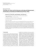
in Ta bl e 1.InFigure 9, we plot the dependency of the mean
nrtPS packet delay on the arrival rate for different groupings,
that is, for different values of P.
The next example in Figure 10 shows the nrtPS delay
of SS
1
within the simplest asymmetric system of 2 SSs and
different priority weights w
1
and w
2
.
Both Figures 9 and 10 show very good accordance
between the analytical and the simulation values.
6.2. Influence of UGS and (e)rtPS TrafficonnrtPSDelay.
In this subsection, we study the influence of the capacity
allocation for the UGS and the real-time traffic on the mean
10.80.60.40.20
Normalized arrival rate
5
10
15
20
25
30
35
40
Mean nrtPS delay for SS
1
(ms)
Analysis, w
1
: w
2
= 1:5
Simulation, w
1
: w
2
= 1:5
Analysis, w
1
: w
2
= 1:2
Simulation, w
1
: w
2
= 1:2
Analysis, w
1
: w
2
= 1:1
Simulation, w
1
: w
2
= 1:1
Figure 10: Mean nrtPS packet delay at SS
1
in asymmetric system
(N
= 2).
10.80.60.40.20
Normalized arrival rate
5
10
15
20
25
30
35
40
45
Mean nrtPS delay (ms)
Analysis, UGS = 0
Simulation, UGS
= 0
Analysis, UGS
= 6
Simulation, UGS
= 6
Analysis, UGS
= 12
Simulation, UGS
= 12
Figure 11: Influence of the UGS traffic on the mean nrtPS packet
delay in symmetric system (N
= 6).
packet delay of the nrtPS service flow in the symmetric
system for N
= 6.
In particular, Figure 11 demonstrates the dependency of
the mean overall nrtPS delay on the normalized arrival rate
for different total UGS capacity values per frame. Here, the
minimum and the maximum (e)rtPS capacity per frame
is set 6 and 12 packets, respectively. It can be seen in the
Figure 11 that increasing the total UGS capacity per frame
leads to higher mean overall nrtPS delay, as expected. This
is due to the impact of the total UGS capacity on the
10 EURASIP Journal on Wireless Communications and Networking
10.80.60.40.20
Normalized arrival rate
5
10
15
20
25
30
35
40
Mean nrtPS delay, uniform distribution (ms)
Analysis, max. (e)rtPS = 12
Simulation, max. (e)rtPS
= 12
Analysis, max. (e)rtPS
= 18
Simulation, max. (e)rtPS
= 18
Analysis, max. (e)rtPS
= 24
Simulation, max. (e)rtPS
= 24
(a)
10.80.60.40.20
Normalized arrival rate
8
9
10
11
12
13
14
15
Mean nrtPS delay, geometric distribution (ms)
Analysis, max. (e)rtPS = 12
Simulation, max. (e)rtPS
= 12
Analysis, max. (e)rtPS
= 18
Simulation, max. (e)rtPS
= 18
Analysis, max. (e)rtPS
= 24
Simulation, max. (e)rtPS
= 24
(b)
Figure 12: Influence of (e)rtPS traffic on the mean nrtPS packet delay in symmetric system (N = 6) for uniform distribution (a) and for
truncated geometric distribution with parameter 0.5 (b).
transmission and scheduling delays (see relations (21)and
(2)).
Now, we vary the maximum (e)rtPS capacity per frame.
In Figure 12, the mean overall nrtPS delay is plotted as
a function of the normalized arrival rate for different
maximum (e)rtPS capacity values per frame, as well as both
uniform and truncated geometric distributions. Here, the
UGS capacity per frame is set 0 packets, and the minimum
(e)rtPS capacity per frame is 6 packets. We can observe in
the figure that the dependency on the maximum (e)rtPS
capacity values for uniform distribution is similar to the
dependency for the total UGS capacity (see Figure 11).
However, comparing the left and the right sides of Figure 12,
we can conclude that the distribution of the (e)rtPS capacity
values has an essential impact on the mean overall nrtPS
delay. The positions of the curves relatively to each other on
the right side of Figure 12 are the consequences of the used
truncating of the geometric distribution.
6.3. Enforcing an Uppe r Bound on Mean Delay. Our model-
ing can be also used to enforce specified upper bounds on
meannrtPSpacketdelaysateverySSinaspecifiedrangeof
loads. These bounds can be different for the individual SSs.
In this case, the total amount of uplink real-time capacities
in the network (
N
i
=1
C
u
i
+
N
i
=1
R
i
) is maximized over a
restricted parameter set, which is determined by the specified
upper bounds on mean nrtPS packet delays and by the
specified range of loads. The priority weights of the SSs are
assumed to be given.
6.4. Cost Model. In case of a more general QoS requirement
(delay constraint), an appropriate cost model can be built
to determine the optimal parameters of the real-time traffic
flows. We developed a steady-state average cost function
F (ω), where the set of priority weights of the SSs ω
=
(ω
1
, , ω
N
) is the decision variable. The parameters of the
cost function for i
= 1, , N are defined as
ξ
i
≡ cost of the mean packet delay at SS i.
θ
i
≡ reward of the UGS capacity at SS i
C
u
i
.
ϑ
i
≡ reward of the maximum
(
e
)
rtPS capacity
at SS i
R
max
i
.
(23)
Then, the optimal parameters of the real-time traffic
flows can be obtained by minimizing the total average system
cost, which is given by
F
(
ω
)
=
N
i=1
ξ
i
E
[
W
i
]
+
θ
i
C
u
i
+
ϑ
i
R
max
i
.
(24)
The minimum can be numerically determined as a
function of the load and the real-time capacity parameters
at every SS (C
u
i
and the distribution of R
i
for i = 1, , N),
by applying the expressions for the mean overall delay of the
tagged i-packet (22).
7. Conclusion
We presented an analytical model for the delay of the uplink
nrtPS traffic in IEEE 802.16-based network, in which
(i) the influence of the real-time (UGS and (e)rtPS)
capacity allocation on the delay of the delay-tolerant
(nrtPS) trafficiscaptured,
EURASIP Journal on Wireless Communications and Networking 11
(ii) the variable nrtPS capacity of each SS is allowed to
depend on the real-time capacities of every SS,
(iii) the nrtPS capacity at the SSs are determined by means
of priorities among them.
The considered analytical model is verified by means of
simulation. This verification shows an excellent accordance
between the analytical and the simulation results in a wide
range of parameter settings. Hence, our analytical model can
be applied to model and analyze the delay of the uplink nrtPS
traffic in IEEE 802.16-based network.
Based on the numerical examples for the performance
evaluation, the following conclusions can be drawn.
(i) The dependencies of the mean nrtPS packet delay on
the total UGS capacity and on the maximum (e)rtPS
capacity for uniform distribution show similar ten-
dencies.
(ii) The distribution of the (e)rtPS capacity has essential
impact on the mean nrtPS packet delay.
These conclusions remain valid also in case of non-
saturated BE traffic, since the BE traffic does not influence
the nrtPS packet delay. This is due to the applied capacity
allocation rule, in which the nrtPS traffichaspriorityover
the BE traffic at the same SS.
The presented analytical model also enables to enforce
specified upper bounds on the mean nrtPS packet delays
at every SS in a specified range of loads. In this case, the
optimal value of the total amount of real-time capacities can
be determined.
In case of a more general QoS requirement (delay con-
straint), the optimal set of priority weights of the SSs can be
determined by using a specific cost model (see Section 6.4).
Acknowledgments
This work is supported by Tampere Graduate School in
Information Science and Engineering, Nokia Foundation,
and HPY Research Foundation.
References
[1] IEEE 802.16-2009, “Part 16, Air Interface for Broadband
Wireless Access Systems, Standard for Local and Metropolitan
Area Networks,” May 2009.
[2] IEEE 802.16.2-2004, “IEEE Recommended Practice for Local
and Metropolitan Area Networks—Coexistence of Fixed
Broadband Wireless Access Systems,” March 2004.
[3] WiMAX Forum, />[4] G. S. Paschos, I. Papapanagiotou, C. G. Argyropoulos, and
S. A. Kotsopoulos, “A heuristic strategy for IEEE 802.16
WiMAX scheduler for quality of service,” in Proceedings of
the 45th FITCE Congress (FITCE ’06), Athens, Greece, August-
September 2006.
[5] L. F. M. de Moraes and P. D. Maciel, “A variable priorities MAC
protocol for broadband wireless access with improved channel
utilization among stations,” in Proceedings of the International
Telecommunications Symposium (ITS ’06), vol. 1, pp. 398–403,
September 2006.
[6] Y. J. Chang, F. T. Chien, and C. C. J. Kuot, “Delay analysis
and comparison of OFDM-TDMA and OFDMA under IEEE
802.16 QoS framework,” in IEEE Global Telecommunicat ions
Conference (GLOBECOM ’06), December 2006.
[7]D.H.Cho,J.H.Song,M.S.Kim,andK.J.Han,“Perfor-
mance analysis of the IEEE 802.16 wireless metropolitan area
network,” in Proceedings of the 1st International Conference on
Distributed Frameworks for Multimedia Applications (DFMA
’05), pp. 130–137, February 2005.
[8] A. Vinel, Y. Zhang, Q. Ni, and A. Lyakhov, “Efficient request
mechanism usage in IEEE 802.16,” in IEEE Global Telecommu-
nications Conference (GLOBECOM ’06), December 2006.
[9] M. C. Wood, “An analysis of the design and implementation
of QoS over IEEE 802.16,” Tech. Rep., Washington University,
St. Louis, Mo, USA, 2006.
[10] I. Rubin, “Access-control disciplines for multi-access com-
munication channels: reservation and TDMA schemes,” IEEE
Transactions on Information Theory, vol. 25, no. 5, pp. 516–
536, 1979.
[11] S. Andreev, Z. Saffer, A. Turlikov, and A. Vinel, “Overall delay
in IEEE 802.16 with contention-based random access,” in
Proceedings of the 16th International Conference on Analytical
and Stochastic Modelling Techniques and Applications (ASMTA
’09), vol. 5513 of Lecture Notes in Computer Science, pp. 89–
102, Madrid, Spain, June 2009.
[12] S. Andreev, Z. Saffer, A. Turlikov, and A. Vinel, “Upper
bound on overall delay in wireless broadband networks with
non real-time traffic,” in Proceedings of the 17th International
Conference on Analytical and Stochastic Modelling Techniques
and Applications (ASMTA ’10), vol. 6148 of Lecture Notes in
Computer Science, pp. 262–276, Cardiff, UK, June 2010.
[13] R. Iyengar, P. Iyer, and B. Sikdar, “Delay analysis of 802.16
based last mile wireless networks,” in IEEE Global Telecom-
munications Conference (GLOBECOM ’05), pp. 3123–3127,
December 2005.
[14] Z. Saffer and S. Andreev, “Delay analysis of IEEE 802.16
wireless metropolitan area network,” in Proceedings of the
International Workshop on Multiple Access Communications
(MACOM ’08), 2008.
[15] S. Andreev, Z. Saffer, and A. Anisimov, “Overall delay
analysis of IEEE 802.16 network,” in Proceedings of the 2nd
International Workshop on Multiple Access Communications
(MACOM ’09), 2009.
[16] L. Lin, W. Jia, and W. Lu, “Performance analysis of IEEE 802.16
multicast and broadcast polling based bandwidth request,”
in
Proceedings of the IEEE Wireless Communications and
Networking Conference (WCNC ’07), pp. 1854–1859, March
2007.
[17] Z. Saffer, S. Andreev, and Y. Koucheryavy, “Modeling the
influence of the real-time traffic on the delay of the non real-
time traffic in IEEE 802.16 network,” in Proceedings of the 3rd
International Workshop on Multiple Access Communications
(MACOM ’10), pp. 151–162, Barcelona, Spain, 2010.
[18] IEEE Std 802.16m, “Part 16: Air Interface for Broadband
Wireless Access Systems—Advanced Air Interface”.
[19] Z. Saffer and S. Andreev, “Selected lectures on multiple access
and queuing systems,” in Mean Delay Estimation for Wireless
Broadband Networks, pp. 77–85, SUAI, St. Petersburg, Russia,
2008.
[20] M. L. Chaudhry and J. G. C. Templeton, A First Course in Bulk
Queues, John Wiley & Sons, New York, NY, USA, 1983.
12 EURASIP Journal on Wireless Communications and Networking
[21] D. Sivchenko, N. Bayer, B. Xu, V. Rakocevic, and J. Haber-
mann, “Internet traffic performance in IEEE 802.16 net-
works,” in Proceedings of the 12th European Wireless Confer-
ence, Athens, Greece, April 2006.
[22] C. So-In, R. Jain, and A K. Tamimi, “Capacity evaluation for
IEEE 802.16e mobile WiMAX,” JournalofComputerSystems,
Networks, and Communications, vol. 2010, Article ID 279807,
12 pages, 2010.