Báo cáo hóa học: " Research Article Network Coding-Based Retransmission for Relay Aided Multisource Multicast Networks" pot
Bạn đang xem bản rút gọn của tài liệu. Xem và tải ngay bản đầy đủ của tài liệu tại đây (815.49 KB, 10 trang )
Hindawi Publishing Corporation
EURASIP Journal on Wireless Communications and Networking
Volume 2011, Article ID 643920, 10 pages
doi:10.1155/2011/643920
Research Ar ticle
Network Coding-Based Retransmission for
Relay Aided Multisource Multicast Networks
Quoc-Tuan Vien,
1
Le-Nam Tran,
2
and Een-Kee Hong
3
1
School of Engineering & Computing, Glasgow Caledonian University, Cowcaddens Road, Glasgow G4 0BA, UK
2
Signal Processing Laboratory, ACCESS Linnaeus Center, KTH Royal Institute of Technology, 100 44 Stockholm, Sweden
3
School of Electronics and Information, Kyung Hee University, Yongin, Gyeonggi-do 446-701, Republic of Korea
Correspondence should be addressed to Een-K ee Hong,
Received 7 April 2010; Revised 24 January 2011; Accepted 13 February 2011
Academic Editor: Michael Gastpar
Copyright © 2011 Quoc-Tuan Vien et al. This is an open access article distributed under the Creative Commons Attribution
License, which permits unrestricted use, distribution, and reproduction in any medium, provided the original work is pr operly
cited.
This paper considers the reliable transmission for wireless multicast networks where multiple sources want to distribute
information to a set of destinations with assistance of a relay. Basically, the reliability of a communication link is assured via
automatic repeat request (ARQ) protocols. In the context of multisource multicast networks, the challenge is how to retransmit
the lost or erroneous packets efficiently. In traditional approaches, the retransmission of lost packets from a sing le source is
treated separately, and thus it may cause a considerable delay. To solve this problem, we propose the relay detects, combines,
and forwards the packets which are lost at destinations using network coding. In the proposed ARQ protocol, the relay detects
packets from different s ources and combines the lost packets using NC. In particular, two packet-combination algorithms are
developed to guarantee that all lost packets are retransmitted with the smallest nu mber of retransmissions. Furthermore, we
analyze the transmission bandwidth and provide the numerical results to demonstrate the superior performance of the proposed
ARQ protocol over some existing schemes.
1. Introduction
Recently, relay communication has been extensively inves-
tigated as a promising technique to extend the coverage of
wireless networks by exploiting the spatial diversity gains
[1–3]. Generally, the use of relays does not immediately
increase the network throughput since packets traverse along
the relays via store-and-forward manner. For some particular
network topologies such as two-way relay channels, relay-
assisted broadcast channels, and multicast channels, the net-
work throughput can be dramatically improved by applying
network coding (NC) at the relays [4–9]. The basic idea
of NC is that the relays are allowed to perform algebraic
linear operations on the received packets from multiple
sources and forward the combined packet in the subsequent
transmission.
In this paper, we consider the reliable transmission over
multisource-multicast networks [10] with assistance of a
relay, where multiple sources want to transmit their messages
to a set of intended destinations. This network model is
widely applicable in various scenarios, in particular wireless
ad hoc networks, where a set of sources needs to transmit
data to a set of destinations through relays. One way to
deliver information reliably over error-prone channels is to
employ automatic repeat request (ARQ) protocols [11], in
which, if a packet cannot be decoded, it is discarded and
retransmitted. Applying the traditional ARQ techniques to
multicast or broadcast networks may cause considerable
delay for two reasons: (i) the lost packets of different destina-
tions are retransmitted individually and (ii) the retrans-
mission will be repeated until all destinations receive all
packets correctly. To reduce the number of retransmissions,
ARQ schemes based on NC have been proposed in [12, 13].
The relay may XOR the disjointedly erroneous packets
of different destinations and retransmit them to all the
in volving destinations.
The existing NC-based ARQ strategies for reliable wire-
less multicast networks are devised for the deployment
2 EURASIP Journal on Wireless Communications and Networking
S
1
S
2
D
1
D
2
R
Figure 1: Multisource-multicast network model.
scenario where a source distributes information to multiple
intended destinations, as in [5, 14]. The problem of designing
a retransmission mechanism for multisource-multicast net-
works that can achieve a high network throughput efficiency
has received less interest. The NC-based ARQ strategies
for multicast networks proposed in [12]canbereusedfor
multisource-multicast network by viewing a multisource-
multicast network as a superposition of several multicast
networks. More specifically, the lost packets in the same
information flow can be XORed using the NC-based ARQ
strategies for multicast networks. Here, The information flow
is defined as the data transmission from a source to multiple
destinations. However, this traditional NC-based ARQ may
result in a poor throughput efficiency since the information
flows from distinct sources are treated independently.
In this paper, we propose a new NC-based ARQ protocol
for multisource-multicast networks, in which the relay de-
tects, combines, and sends the lost packets from different
sources to the destinations. To achieve the best performance,
multiuser detection (MUD) techniques, such as optimum
detector, linear decorrelating detector, decision-feedback
detector, and successive interference cancellation. [15–19]
are employed at the relay and destinations.
Thus, many lost packets from different sources can be
combined and retransmitted. We need to develop an ARQ
protocol to retransmit these lost packets in a systematic and
efficient way. First, we classify lost packets into two types:
Type-I includes the packets that are lost at the destinations
but successfully received at the relay, and Type-II packets are
lost at both destinations and the relay. Obviously, the sources
must handle the retransmission of Type-II packets. The
retransmission algorithm based on NC for sources can be
easily designed since these packets are in the same flow, and
thus it becomes the classical application of NC. The problem
is how the relay efficiently retransmits Type-I packets that can
come from different sources.
Dealing with that problem, we propose an algorithm at
the relay to retransmit Type-I packets and an algorithm at
the source to retransmit Type-II packets. Particularly, the
algorithm for the retransmission at the relay is proposed
based on an integration of NC and packet detection from two
different sources.
12 109876543
12 109876543
12 109876543
12 109876543
12 109876543
12 109876543
185
1
4
49
123 7 1068
3
9
5
12 35687108
35
1521081 6278
2
3
2
⊕⊕ ⊕
⊕
⊕
⊕
⊕⊕⊕⊕
S
1
−→ R
S
2
−→ R
S
1
−→ D
1
S
2
−→ D
1
S
1
−→ D
2
S
2
−→ D
2
R
R
S
1
S
2
R
S
1
S
2
RT protocol
Proposed protocol
Traditional NC-based ARQ protocol
Transmission phase
Retransmission phase
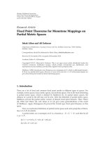
Figure 2: Retransmission with RT, traditional NC-based ARQ, and
our proposed protocol.
Unlike the traditional NC-based ARQ, the proposed
method can combine the packets from different flows and
thus can improve the network throughput for multisource-
multicast networks. As we show later in an example
(Figure 2), with our proposed ARQ protocol, the number
of retransmissions is significantly reduced, comparing with
other ARQ-based protocols. As a second contribution of
the paper, we compare our proposed method with other
ARQ-based protocols for multisource-multicast networks
by evaluating the transmission bandwidth with theoretical
analysis and numerical results. In fact, three protocols
are taken into account: direct transmission (DT), relaying
transmission (RT), and the traditional NC-based ARQ. DT
protocol denotes the case when multiple sources simultane-
ously transmit information to destination without relaying
technique. RT protocol represents the model where relay
participates in the transmission but NC is not performed at
the relay (e.g., decode-and-forward relaying technique [2]).
The rest of this paper is organized as follows. In Section 2,
we describe the system model of a multisource-multicast
network. Different retransmission protocols are also pre-
sented in this section, and their transmission bandwidths
are derived in Section 3.Weprovidethenumericalresultsin
Section 4 and Section 5 concludes this paper.
2. System Model and Transmission Protocols
The system model under investigation is shown in Figure 1.
The data delivery from two sources S
1
and S
2
to two
destinations D
1
and D
2
is assisted by a relay R.Thisisa
specific case of multisource-multicast networks where the
EURASIP Journal on Wireless Communications and Networking 3
numbers of sources and destinations are 2 and 2, respectively.
The generalization to cope with more than two sources and
two destinations is straightforward.
In this paper, we assume that the sources send data in the
form of packets (i.e., packet-based transmission) and each
packet must be received correctly by all destinations after
several transmissions and retransmissions. The packet loss
of transmission from S
i
to R,fromS
i
to D
j
,andfromR
to D
j
follows Bernoulli trial with parameters p
s
i
r
, p
s
i
d
j
,and
p
rd
j
, respectively. We also assume that the sources and the
relay are equipped with sufficient signal processing modules
to be able to perform NC, that is, algebraic operation such as
bitwise XOR oper ation.
Receiving the information data from multiple sources
along with the feedback from the destinations, the relay
knows what destinations are waiting for the lost packets to be
retransmitted and then decides how to combine and forward
the data to the intended destinations. In the following, we
introduce some protocols that allow the relay to resend
the lost packets to the destinations. The two fundamental
DT and R T protocols are presented first, and our proposed
protocol is followed.
2.1. DT Protocol. In this protocol, the sources send data
directly to two destinations. The transmission is carried
out with the traditional ARQ scheme and completed if two
destinations receive correctly the data from two sources.
2.2. RT Protocol. This protocol is different from DT protocol
in that the relay participates in the transmission. When
one or two destinations do not receive the packet correctly,
whereas the relay receives this packet successfully, the relay
can help the source to forward the correctly received packet
to the erroneously received destinations in the next time
slot. The retransmission at the relay will be continued until
its transmitted packet is correctly received by the intended
destinations. In case that one or two destinations and the
relay fail to receive the same packet from the sources, it is
obvious that the sources need to resend that lost packet.
2.3. Proposed Protocol. Instead of resending the lost packet as
soon as the destinations fail to receive it, the retransmission
in the proposed ARQ protocol will happen after N packets.
The buffer of length N is required at two sources, whereas
the buffer of length 2N is required at the relay and two
destinations since they receive packets from two different
sources. To improve the network throughput, the relay
retransmits the packets of Ty p e-I, and the sources deal w ith
the retransmission of Type-II packets. What is particular in
the proposed ARQ strategy is that the relay can mix the
packets from different data flows.
Let us describe the proposed protocol by examining an
example shown in Figure 2,whereS
i
wishes to deliver 10
packets s
i
[1], s
i
[2], , s
i
[10] to D
1
and D
2
.
The packets with a crossover sign represent the lost
or erroneous packets. Without loss of generality, we
assume that, for the data flow from S
1
,theerroneous
packets received at R, D
1
,andD
2
are {s
1
[4], s
1
[9]},
{s
1
[5], s
1
[9], s
1
[10]},and{s
1
[1], s
1
[2], s
1
[3], s
1
[4], s
1
[8]},re-
spectively. Similarly, the erroneous packets received at R,
D
1
,andD
2
from S
2
are assumed to be {s
2
[3], s
2
[5]},
{s
2
[1], s
2
[2], s
2
[5], s
2
[6], s
2
[8]},and{s
2
[3], s
2
[6], s
2
[7]},re-
spectively.
As shown in Figure 2, R needs to retransmit 11
packets if applying RT protocol. The number of re-
transmissions can be significantly reduced with the tradi-
tional NC-based ARQ scheme where R would transmit
{s
1
[1] ⊕ s
1
[5], s
1
[2] ⊕ s
1
[10], s
1
[3], s
1
[8]},and{s
2
[1] ⊕
s
2
[7], s
2
[2], s
2
[6], s
2
[8]}. In t his scheme, we could not com-
bine s
1
[3] and s
1
[8] since both of them are corrupted at
D
2
. Similarly, there is no way to combine s
2
[2], s
2
[6],
and s
2
[8] since s
2
[2] and s
2
[8] are simultaneously lost
at D
2
and s
2
[6] is lost at both D
1
and D
2
.Thus,8
retransmissions are totally required for the traditional NC-
based ARQ scheme. That helps R save 3 retransmissions.
Not stopping at that, we can further reduce the number of
retransmissions with our proposed scheme if packets from
different data flows are detected in parallel at R, D
1
,and
D
2
. As in our above definition, packets {s
1
[1], s
2
[1], s
1
[2],
s
2
[2], s
1
[3], s
1
[5], s
2
[6], s
2
[7], s
1
[8], s
2
[8], s
1
[10]} are Type-I
packets. To improve the network throughput, R forwards
{s
1
[1]⊕s
2
[1], s
1
[2]⊕s
2
[2], s
2
[7]⊕s
2
[8], s
1
[8]⊕s
1
[10], s
1
[3]⊕
s
1
[5], s
2
[6]} in the retransmission phase. The details of this
combination algorithm are presented in Algorithm 1.That
means, the proposed ARQ requires 6 retransmissions and
thus can save 2 further retransmissions comparing with
the traditional NC-based ARQ scheme. R retransmits these
packets until they are successfully received by both D
1
and
D
2
.
We can se e that s
1
[4], s
1
[9], s
2
[3], and s
2
[5] are lost at R
and also lost at D
1
and/or D
2
. These packets are classified
as Type-II packets. Obviously, the relay has no way to
resend such packets, and thus the sources must resend these
packets. In the example, S
1
and S
2
retransmit the combined
packets
{s
1
[4] ⊕ s
1
[9]} and {s
2
[3] ⊕ s
2
[5]}, respectively. The
destinations are able to recover the corrupted packets by
XORing their correctly received packets with the XORed
packets received from the relay or sources.
The generalization of the above example for the arbitrary
buffer size is summarized in Figure 3. In this protocol,
the combination algorithms at the relay and sources are
presented in Algorithms 1 and 2 , respectively.
3. Transmission Bandwidth Analysis
In this section, we study the transmission bandwidth of
different transmission protocols in multisource-multicast
networks consisting of two sources, one relay, and two
destinations. The transmission bandwidth is defined as
the average number of transmissions that is required to
successfully transmit two packets from two sources to two
destinations.
3.1. DT Protocol. This protocol is the simplest in which two
sources directly send packets to two destinations without
4 EURASIP Journal on Wireless Communications and Networking
R checks received
packets
R decides which packets should be sent to D
1
and
D
2
, and how to combine these packets in an
effective way based on Algorithm 1
D
1
and D
2
receive
successfully?
D
1
and D
2
receive
successfully?
No
No
No
No
No
Yes
Yes
Yes
Yes
Yes
D
1
and D
2
receive
packets from R
successfully?
Is there any left lost
packets in D
1
and D
2
?
R receives
successfully?
R sends to D
1
and D
2
S
1
and S
2
resend lost packets by RT
protocol and in an effective way based
on Algorithm 2
S
1
and S
2
send N
successive packets
Figure 3: Block diagram of proposed protocol.
relay and network coding. The transmission bandwidth is
given by
n
DT
= max
n
(s
1
)
DT
, n
(s
2
)
DT
,(1)
where n
(s
i
)
DT
, i = 1, 2, denotes the average number of
transmissions required for S
i
to send data to both D
1
and
D
2
and is calculated as [13]
n
(s
i
)
DT
=
1
1 − p
s
i
d
1
+
1
1 − p
s
i
d
2
−
1
1 − p
s
i
d
1
p
s
i
d
2
. (2)
3.2. RT Protocol. In this protocol, the relay helps two
sources in sending data to two destinations, but no NC is
applied at the relay. The transmission bandwidth required
to successfully transmit two packets from S
1
and S
2
to D
i
,
i
= 1, 2, is given by
n
(d
i
)
RT
=
1
1 − p
s
1
r
p
s
2
r
p
s
1
d
i
p
s
2
d
i
×
1+p
s
1
r
p
s
1
d
i
1 − p
s
2
d
i
n
(s
1
,d
i
)
RT
+ p
s
2
r
1 − p
s
1
d
i
p
s
2
d
i
n
(s
2
,d
i
)
RT
+
1 − p
s
1
r
p
s
1
d
i
1 − p
s
2
d
i
n
rd
i
+
1 − p
s
2
r
1 − p
s
1
d
i
p
s
2
d
i
n
rd
i
+2
1 − p
s
1
r
1 − p
s
2
r
p
s
1
d
i
p
s
2
d
i
n
rd
i
+
1 − p
s
1
r
p
s
2
r
p
s
1
d
i
p
s
2
d
i
n
rd
i
+ n
(s
2
,d
i
)
RT
+p
s
1
r
1 − p
s
2
r
p
s
1
d
i
p
s
2
d
i
n
rd
i
+ n
(s
1
,d
i
)
RT
,
(3)
where n
(s
i
,d
j
)
RT
denotes the average number of transmissions to
send a packet from S
i
to D
j
with the help of R and is found
as [12]
n
(s
i
,d
j
)
RT
=
1+p
rd
j
+ p
s
i
d
j
1 − p
s
i
r
1 − p
s
i
r
p
s
i
d
j
1 − p
rd
j
. (4)
Finally, the transmission bandwidth of this protocol is
n
RT
= max
n
(d
1
)
RT
, n
(d
2
)
RT
. (5)
3.3. Traditional NC-Based ARQ Protocol. The relay in this
protocol combines the lost packets in the same flow based
on NC in the retransmission phase. The transmission
bandwidth is given by
n
NCA
= max
n
(s
1
)
NCA
, n
(s
2
)
NCA
,(6)
where n
(s
i
)
NCA
, i = 1, 2, denotes the average number of
transmissions to transmit from S
i
to both D
1
and D
2
with
the help of R in the traditional NC-based ARQ (NCA)
protocol. Note that the data delivery from S
i
to D
1
and D
2
through R resembles the system model in [12]. However,
the analysis of transmission bandwidth presented in [12]
is difficult to follow. Here, we introduce a simple way to
calculate the transmission bandwidth.
In this protocol, there are three steps to transmit data
from S
i
to D
1
and D
2
through R.
Step 1. S
i
transmits N packets.
Step 2. R retransmits Type-I packets.
Step 3. S
i
retransmits Type-II packets.
Let n
(s
i
, j)
NCA
, i ∈{1,2}, j ∈{1, 2, 3}, denote the number of
transmissions in the jth step of the traditional NCA protocol.
EURASIP Journal on Wireless Communications and Networking 5
(1) Let
1
and
2
denote the ordered set of correctly rec eived packet at R transmitted from S
1
and S
2
, r espectively:
1
={s
1
[i
1
], s
1
[i
2
], , s
1
[i
m
]},wherei
1
<i
2
< ··· <i
m
∈{1, 2, , N},
2
={s
2
[ j
1
], s
2
[ j
2
], , s
2
[ j
n
]},where j
1
<j
2
< ··· <j
n
∈{1, 2, , N}.
Define Ω
=
1
∪
2
and divide Ω into 3 groups:
(i) Group Ω
1
includes packets that R receives successfully from both S
1
and S
2
,thatis,
Ω
1
={(s
1
[i], s
2
[ j]) | i = j}. In the preceding example, (s
1
[1], s
2
[1]), (s
1
[2], s
2
[2]),
(s
1
[6], s
2
[6]), (s
1
[7], s
2
[7]), (s
1
[8], s
2
[8]), and (s
1
[10], s
2
[10]) belongs to Ω
1
,
(ii) Group Ω
2
includes packets that R receives successfully from S
1
but fails to receive from
S
2
,thatis,Ω
2
={s
1
[i] | i/∈{j
1
, j
2
, , j
n
}}.InFigure 2, Ω
2
includes s
1
[3] and s
1
[5].
(iii) Group Ω
3
includes packets that R receives successfully from S
2
but fails to receive from
S
1
: Ω
3
={s
2
[ j] | j/∈{i
1
, i
2
, , i
m
}}.InFigure 2, Ω
3
includes s
2
[4] and s
2
[9].
(2) For packets in Ω
1
, if one packet is correctly received at D
1
,lostatD
2
, while another packet is
correctly received at D
2
,lostatD
1
,wecancombinethesetwopackets.
Thus, there are 3 possibilities: s
1
[k
1
] ⊕ s
2
[k
2
]ors
1
[m
1
] ⊕ s
1
[m
2
]ors
2
[n
1
] ⊕ s
2
[m
2
].
Start from left to right in the group of packets in Ω
1
, and choose the suitable combination
(e.g., s
1
[1] ⊕ s
2
[1], s
1
[2] ⊕ s
2
[2], s
2
[7] ⊕ s
2
[8], and s
1
[8] ⊕ s
1
[10] in the above example)
(3) For packets in Ω
2
and Ω
3
, similarly if one packet is correctly received at D
1
,lostatD
2
,
while another packet is correctly recei ved at D
2
,lostatD
1
, we can combine these two packets
in only one way s
1
[m
1
] ⊕ s
1
[m
2
](forΩ
2
)ors
2
[n
1
] ⊕ s
2
[m
2
](forΩ
3
). (e.g., s
1
[3] ⊕ s
1
[5]
in the above example)
(4) For the remaining lost packets at D
1
and D
2
that R receives successfully but cannot perform
the combination, they are normally resent w ithout using NC (e.g., s
1
[6] in the above example)
Algorithm 1: Algorithm at relay to retransmit Type-I packets.
(1) Through the feedback from D
1
, D
2
,andR, S
i
determines the number and the position of
remaining lost packets at destinations that R also fails in receiving them.
(2) Combine the packets for retransmission by NC with the condition that only one packet in
the combined packet should be correctly received by only one destination, similar to the
combination performed for packets in Ω
2
and Ω
3
explained in Algorithm 1. In the preceding
example, S
1
resends s
1
[4] ⊕ s
1
[9] and S
2
resends s
2
[3] ⊕ s
2
[5].
(3) For the remaining lost packets at D
1
and D
2
that S
i
cannot perform the combination,
they are resent without using NC.
Algorithm 2: Algorithm at source to retransmit Type-II packets.
The average n umber of transmissions to send from S
i
to both
D
1
and D
2
is calculated by
n
(s
i
)
NCA
=
n
(s
i
,1)
NCA
+ n
(s
i
,2)
NCA
+ n
(s
i
,3)
NCA
N
,(7)
where the number of transmissions in Step 1 is simply given
by
n
(s
i
,1)
NCA
= N. (8)
The number of transmissions in Step 2 and in Step 3 is
calculated by
n
(s
i
,2)
NCA
=
N
k=0
C
N
k
p
N−k
s
i
r
1 − p
s
i
r
k
E
n
(s
i
,2)
NCA
| K = k
,(9)
n
(s
i
,3)
NCA
=
N
k=0
C
N
k
p
N−k
s
i
r
1 − p
s
i
r
k
E
n
(s
i
,3)
NCA
| K = k
,
(10)
respectively , where E[
·] denotes the expectation, C
N
k
is the
total number of subsets consisting of k elements in a set of
N elements, and K is a random variable representing the
number of packets that R successfully receives in the first
step.
Given that K
= k packets are successfully r eceived at
R in the first step, the number of transmissions at R using
traditional NCA protocol in the second step can be computed
by
E
n
(s
i
s
,2)
NCA
| K = k
=
k
i=0
k
j=0
C
k
i
p
i
s
i
s
d
1
1 − p
s
i
s
d
1
k−i
C
k
j
p
j
s
i
s
d
2
1 − p
s
i
s
d
2
k− j
×
min
i, j
n
(r)
DT
+
i − j
n
rd
a
,
(11)
where i
s
∈{1, 2}, n
(r)
DT
is the av erage number of transmissions
required at R to send a packet to both D
1
and D
2
,and
n
rd
a
is the average number of transmissions for a direct
transmission from R to D
a
,wherea = 1ifi> j,anda = 2
6 EURASIP Journal on Wireless Communications and Networking
otherwise. The term [min
{i, j} n
(r)
DT
+ |i − j|n
rd
a
]in(11)is
derived based on the fact that there are min
{i, j} packets
that the relay can combine with NC, and thus the number
of transmissions is given by min
{i, j} n
(r)
DT
.Then,therelay
transmits the remaining
|i − j| packets to the corresponding
destination depending on the relation of i and j,thatis,if
i> j,thenR transmits (i
− j)packetstoD
1
,otherwise
R transmits (j
− i)packetstoD
2
. Wit h these packets, the
number of transmissions is given by
|i − j|n
rd
a
.Thus,n
rd
a
and n
(r)
DT
are, respectively, g iven by
n
rd
a
=
1
1 − p
rd
a
,
(12)
n
(r)
DT
=
1
1 − p
rd
1
+
1
1 − p
rd
2
−
1
1 − p
rd
1
p
rd
2
.
(13)
In the third step where R fails to receive (N
− k)packets
in the first step, S
i
is required to retransmit with the number
of transmissions
E
n
(s
i
s
,3)
NCA
| K = k
=
N−k
i=0
N
−k
j=0
C
N−k
i
p
i
s
i
s
d
1
1 − p
s
i
s
d
1
N−k−i
× C
N−k
j
p
j
s
i
s
d
2
1 − p
s
i
s
d
2
N−k− j
×
min
i, j
n
RT
+
i − j
n
rd
a
,
(14)
where i
s
∈{1, 2}, a = 1ifi>j,anda = 2otherwise.n
RT
and
n
rd
a
are given by (5)and(12), respectively.
3.4. Proposed Protocol. Therelayintheproposedprotocol
combines the lost packets of different flows. Since the total of
2N packets is transmitted from S
1
and S
2
, the transmission
bandwidth is expressed as
n
=
n
(1)
+ n
(2)
+ n
(3)
2N
, (15)
where n
(i)
denotes the number of transmissions in the ith step
of the proposed protocol including the following steps.
Step 1. Each of S
1
and S
2
transmits N packets.
Step 2. R retransmits Type-I packets.
Step 3. S
1
and/or S
2
retransmit Type-II packets.
In Step 1,bothS
1
and S
2
send N packets to R, D
1
,andD
2
,
and thus
n
(1)
= 2N. (16)
The number of transmissions in Step 2 and Step 3 are
given by
n
(2)
=
N
k=0
C
N
k
p
N−k
s
1
r
1 − p
s
1
r
k
× p
N−k
s
2
r
1 − p
s
2
r
k
E
n
(2)
| K = k
+
N−k
l=0
C
N−k
l
p
N−k−l
s
1
r
1 − p
s
1
r
l
× p
l
s
2
r
1 − p
s
2
r
N−k−l
E
n
(2)
| L = l
+
N−k−l
m=0
C
N−k−l
m
p
m
s
1
r
1 − p
s
1
r
N−k−l−m
×
1 − p
s
2
r
m
p
N−k−l−m
s
2
r
×E
n
(2)
| M = m
,
(17)
n
(3)
=
N
k=0
C
N
k
p
N−k
s
1
r
1 − p
s
1
r
k
× p
N−k
s
2
r
1 − p
s
2
r
k
E
n
(3)
| K = k
+
N−k
l=0
C
N−k
l
p
N−k−l
s
1
r
1 − p
s
1
r
l
p
l
s
2
r
1 − p
s
2
r
N−k−l
× E
n
(3)
| L = l
+
N−k−l
m=0
C
N−k−l
m
p
m
s
1
r
1 − p
s
1
r
N−k−l−m
×
1 − p
s
2
r
m
p
N−k−l−m
s
2
r
×E
n
(3)
| M = m
,
(18)
respectively , where K, L, M are random variables represent-
ing the number of packets that R successfully receives from
Ω
1
, Ω
2
,andΩ
3
, respectively.
Given that K
= k packets are successfully received at R
in the first group, the number of transmissions at R based
on the proposed algorithm (i.e., Algorithm 1) for the packets
in Ω
1
inthesecondstepcanbecomputedby
E
n
(2)
| K = k
=
k
i=0
k
j=0
k
u=0
k
v=0
C
k
i
p
i
s
1
d
1
1 − p
s
1
d
1
k−i
× C
k
j
p
j
s
2
d
1
1 − p
s
2
d
1
k− j
C
k
u
p
u
s
1
d
2
1 − p
s
1
d
2
k−u
EURASIP Journal on Wireless Communications and Networking 7
× C
k
v
p
v
s
2
d
2
1 − p
s
2
d
2
k−v
×
min
i + j, u + v
n
(r)
DT
+
i + j
−
(
u + v
)
n
rd
a
,
(19)
where n
(r)
DT
is given by (13), n
rd
a
is given by (12)witha = 1if
i + j>u+ v,anda
= 2otherwise.
For the packets in Ω
2
and Ω
3
in Step 2,thenumberof
transmissions is calculated by
E
n
(2)
| L = l
=
l
i=0
l
j=0
C
l
i
p
i
s
1
d
1
1 − p
s
1
d
1
l−i
C
l
j
p
j
s
1
d
2
1 − p
s
1
d
2
l− j
×
min
i, j
n
(r)
DT
+
i − j
n
rd
a
,
(20)
E
n
(2)
| M = m
=
m
i=0
m
j=0
C
m
i
p
i
s
2
d
1
1 − p
s
2
d
1
m−i
C
m
j
p
j
s
2
d
2
1 − p
s
2
d
2
m− j
×
min
i, j
n
(r)
DT
+
i − j
n
rd
a
,
(21)
respectively , where a
= 1ifi>j,anda = 2otherwise.
In Step 3 where the relay fails to receive packets of the
first group in the first step, the sources are required to
retransmit these remaining lost packets with the number of
transmissions
E
n
(3)
| K = k
=
N−k
i=0
N
−k
j=0
N
−k
u=0
N
−k
v=0
C
N−k
i
p
i
s
1
d
1
1 − p
s
1
d
1
N−k−i
× C
N−k
j
p
j
s
2
d
1
1 − p
s
2
d
1
N−k− j
C
N−k
u
p
u
s
1
d
2
×
1 − p
s
1
d
2
N−k−u
C
N−k
v
p
v
s
2
d
2
1 − p
s
2
d
2
N−k−v
×
min
i + j, u + v
n
RT
+
i + j
−
(
u + v
)
n
(d
a
)
RT
,
(22)
where a
= 1ifi + j>u+ v,anda = 2otherwise.n
RT
and
n
(d
a
)
RT
are given by (5)and(3), respectively.
For the second group and the third group in Step 3,the
number of transmissions is computed by
E
n
(3)
| L = l
=
N−k−l
i=0
N
−k−l
j=0
C
N−k−l
i
p
i
s
1
d
1
1 − p
s
1
d
1
N−k−l−i
× C
N−k−l
j
p
i
s
1
d
2
1 − p
s
1
d
2
N−k−l− j
×
min
i, j
n
(s
1
)
RT
+
i − j
n
(s
1
,d
a
)
RT
,
(23)
E
n
(3)
| M = m
=
N−k−l−m
i=0
N
−k−l−m
j=0
C
N−k−l−m
i
p
i
s
2
d
1
1 − p
s
2
d
1
N−k−l−m−i
× C
N−k−l−m
j
p
j
s
2
d
2
1 − p
s
2
d
2
N−k−l−m− j
×
min
i, j
n
(s
2
)
RT
+
i − j
n
(s
2
,d
a
)
RT
,
(24)
respectively , where n
(s
i
,d
a
)
RT
, i = 1, 2, is given by (4); a = 1ifi>
j,anda = 2otherwise.Intheabove(23)and(24), n
(s
i
)
RT
, i =
1, 2, denotes the number of transmissions to transmit data
from S
i
to both D
1
and D
2
through R that can be computed
by
n
(s
i
)
RT
=
1
1 − p
s
i
r
p
s
i
d
1
p
s
i
d
2
×
1+p
s
i
r
p
s
i
d
1
1 − p
s
i
d
2
n
(s
i
,d
1
)
RT
+ p
s
i
r
1 − p
s
i
d
1
p
s
i
d
2
n
(s
i
,d
2
)
RT
+
1 − p
s
i
r
p
s
i
d
1
1 − p
s
i
d
2
n
rd
1
+
1 − p
s
i
r
1 − p
s
i
d
1
p
s
i
d
2
n
rd
2
+
1 − p
s
i
r
p
s
i
d
1
p
s
i
d
2
n
(r)
DT
,
(25)
where n
(r)
DT
is given by (13).
4. Numer ical Results
In this section, we compare the transmission bandwidth of
different protocols considered in our work by analytically
evaluating the expressions in Section 3. In fact, the simula-
tion and analytical results drawn in Figure 4 demonstrate a
strong agreement. Consequently, it is sufficient to show the
analytical results in Figures 5–7.
Figure 4 plots the transmission bandwidth of various
ARQ protocols versus p
s
1
r
, the packet error rate (PER) of the
wireless link from S
1
to R. Both numerical and analytical
results are included. The range of p
s
1
r
is from 0.04 to 0.2 to
characterize a wide range of wireless applications. To study
the effect of the channels from the sources to the relay on
the overall performance, we assume that p
s
1
r
= p
s
2
r
.The
value of other PERs is arbitrarily set at p
s
1
d
1
= p
s
2
d
2
= 0.2,
p
s
1
d
2
= p
s
2
d
1
= 0.3, and p
rd
1
= p
rd
2
= 0.1. We can
see that the proposed protocol outperforms other existing
schemes since it can combine the lost packets from different
flows in the retransmission phase. In particular, when p
s
1
r
is small (e.g., p
s
1
r
= 0.04), the proposed scheme shows a
remarkable gain over the traditional ARQ method. In fact,
8 EURASIP Journal on Wireless Communications and Networking
0.04 0.06 0.08 0.1 0.12 0.14 0.16 0.18 0.2
1
1.2
1.4
1.6
1.8
2
2.2
p
s
1
r
DT (simulation)
DT (analytical)
RT (simulation)
RT (analytical)
Traditional NC-based ARQ (simulation)
Traditional NC-based ARQ (analytical)
Proposed (simulation)
Proposed (analytical)
Transmission bandwidth
Figure 4: Transmission bandwidth of different pr otocols over
p
s
1
r
= p
s
2
r
with p
s
1
d
1
= p
s
2
d
2
= 0.2, p
s
1
d
2
= p
s
2
d
1
= 0.3, and
p
rd
1
= p
rd
2
= 0.1.
if p
s
1
r
is small, we have more Type-I packets in Ω
1
than in
Ω
2
and Ω
3
.ForpacketsinΩ
1
, our proposed scheme can
save the number of retransmissions by mixing the packets
from different flows. When p
s
1
r
is high (i.e., the channel
from sources to relay is in bad condition), the relay mostly
obtains the lost packets of Type-II. Consequently, the sources
should retransmit these packets. In other words, there is little
benefit in applying NC at the relay in this scenario. As a
result, the performance of our proposed protocol converges
to that of the traditional approach. Additionally, it can be
seen that the analytical results are quite matched with the
simulation results, and thus, in the following, we only show
the analytical results.
Figure 5 compares the transmission bandwidth of our
proposed protocol with that of the traditional NC-based
ARQ protocol for different values of PER of the channels
from sources to destinations. The simulation setting is
similar to that in Figure 4. For a given value of p
s
i
d
j
,our
proposed approach always shows better performance than
the traditional NC-based ARQ protocol. What is particular
in Figure 5 is that the transmission bandwidth of our
proposed protocol converges to a certain value at low p
s
1
r
regardless of p
s
1
d
1
and p
s
1
d
2
.Thatmeans,whenp
s
1
r
is small,
the reliability of the channels from sources to destinations
has little impact on the transmission bandwidth of the
proposed protocol. In fact, a small value of p
s
1
r
denotes the
case where R certainly detected the packets from S
1
and S
2
successfully. As a result, the lost packets at the destinations
belong to Type-I. Thus, the relay handles the retransmission
of these packets, and the impact of the direct channels from
sourcestodestinationsisnegligible.
0.04 0.06 0.08 0.1 0.12 0.14 0.16 0.18 0.2
p
s
1
r
1
1.2
1.4
1.6
1.8
2
Transmission bandwidth
Traditional NC-based ARQ (p
s
1
d
1
= 0.2, p
s
1
d
2
= 0.3)
Traditional NC-based ARQ (p
s
1
d
1
= 0.3, p
s
1
d
2
= 0.4)
Traditional NC-based ARQ (p
s
1
d
1
= 0.4, p
s
1
d
2
= 0.5)
Proposed (p
s
1
d
1
= 0.2, p
s
1
d
2
= 0.3)
Proposed (p
s
1
d
1
= 0.3, p
s
1
d
2
= 0.4)
Proposed (p
s
1
d
1
= 0.4, p
s
1
d
2
= 0.5)
Figure 5: Transmission bandwidth comparison of traditional NC-
based ARQ and our proposed protocol for different values of p
s
i
d
j
.
0.1 0.15 0.2 0.25 0.3 0.35 0.4
1
1.2
1.4
1.6
1.8
2
2.2
2.4
2.6
p
s
1
d
1
DT
RT
Traditional NC-based ARQ
Proposed
Transmission bandwidth
Figure 6: Transmission bandwidth of different protocols over
p
s
1
d
1
= p
s
2
d
2
with p
s
1
d
2
= p
s
2
d
1
= p
s
1
d
1
+0.1, p
s
1
r
= p
s
2
r
= 0.1,
and p
rd
1
= p
rd
2
= 0.1.
In Figures 6 and 7, we show the transmission bandwidth
of various ARQ protocols with respect to p
s
1
d
1
.ThePERsof
the channels from the sources to the relay and from the relay
to the destinations are fixed. The values of p
s
1
d
2
and p
s
2
d
1
are
adjusted accordingly to p
s
1
d
1
by the relation p
s
1
d
2
= p
s
2
d
1
=
p
s
1
d
1
+0.1. It is observed that the transmission bandwidth
curve of the proposed protocol has the smallest slope. Thus,
EURASIP Journal on Wireless Communications and Networking 9
0.1 0.15 0.2 0.25 0.3 0.35 0.4
p
s
1
d
1
1
1.1
1.2
1.3
1.4
1.5
1.6
Traditional NC-based ARQ (p
rd
1
= 0.1, p
s
1
r
= 0.1)
Traditional NC-based ARQ (p
rd
1
= 0.1, p
s
1
r
= 0.05)
Traditional NC-based ARQ (p
rd
1
= 0.05, p
s
1
r
= 0.05)
Proposed (p
rd
1
= 0.1, p
s
1
r
= 0.1)
Proposed (p
rd
1
= 0.1, p
s
1
r
= 0.05)
Proposed (p
rd
1
= 0.05, p
s
1
r
= 0.05)
Transmission bandwidth
Figure 7: Transmission bandwidth of traditional NC-based ARQ
and our proposed protocol over p
s
1
d
1
= p
s
2
d
2
with p
s
1
d
2
= p
s
2
d
1
=
p
s
1
d
1
+0.1anddifferent p
s
1
r
= p
s
2
r
, p
rd
1
= p
rd
2
.
we conclude that the performance of our de veloped ARQ
scheme is not sensitive to the quality of the channels from
the sources to the destinations. The channels S
i
→ R and
R
→ D
i
are more important than the channels S
i
→ D
j
.
5. Conclusion
In this paper, we propose a new reliable transmission scheme
for wireless multisource-multicast networks based on NC.
For a specific case of multisource-multicast networks with
two sources and two destinations, we present two pack-
et-combination algorithms to retransmit the lost packets
efficiently. The transmission bandwidth of various ARQ
protocols is analyzed. Furthermore, we provide numerical
results with different simulation settings to demonstrate the
effectiveness of o ur proposed scheme in saving the trans-
mission bandwidth. For future works, one could possibly
investigate the performance of fading channels with path loss
and placement of the nodes.
Acknowledgment
This paper was partly supported by the IT R&D program
of MKE/KEIT (KI001814, Game Theoretic Approach for
Crosslayer Design in Wireless Communications) and this
work 2010-0025926 was partly supported by Mid-career
Researcher Program through NRF grant funded by the
MEST.
References
[1] A. Sendonaris, E. Erk ip, a nd B. Aazhang, “U ser cooperation
diversity—part I: system description,” IEEE Tr ansactions on
Communications, vol. 51, no. 11, pp. 1927–1938, 2003.
[2] J.N.Laneman,D.N.C.Tse,andG.W.Wornell,“Cooperative
diversity in wireless n etworks: efficient protocols and outage
behavior,” IEEE Tr ansactions on Information Theory, vol. 50,
no. 12, pp. 3062–3080, 2004.
[3] B. Nazer and M. Gastpar, “Compute-and-forward: harnessing
interference through structured codes,” in Proceedings of IEEE
International Symposium on Information Theory (ISIT ’08),pp.
772–776, Toronto, Ontar io, Canada, July 2008.
[4]R.Ahlswede,N.Cai,S.Y.R.Li,andR.W.Yeung,“Network
information flow,” IEEE Transactions on Information Theory,
vol. 46, no. 4, pp. 1204–1216, 2000.
[5] R. Koetter and M. M
´
edard, “A n algebraic approach to network
coding,” IEEE/A CM Transactions on Networking, vol. 11, no. 5,
pp. 782–795, 2003.
[6]S.Katti,D.Katabi,W.Hu,H.Rahul,andM.Medard,
“The importance of being opportunistic: practical network
coding for wireless environments,” in Proceedings of the 43rd
Annual Allerton Conference on Communication, Control and
Computing (Allerton ’05), Montecillo, Ill, USA, September
2005.
[7]S.Zhang,S.C.Liew,andP.P.Lam,“Hottopic:physical-
layer network coding,” in Proceedings of the 12th Annual
International Conference on Mobile Computing and Networking
(MOBICOM ’06), pp. 358–365, New York, NY, USA, Septem-
ber 2006.
[8] S. Katti, S . Gollakota, and D. Katabi, “Embracing wireless
interference: analog n etwork coding,” in Proceedings of the
ACM Conference on Applications, Technologies, Architectures,
and Protocols for Computer Communications (SIGCOMM ’07),
pp. 397–408, Kyoto, Japan, August 2007.
[9]S.Katti,H.Rahul,W.Hu,D.Katabi,M.Medard,and
J. Crowcroft, “XORs in the air: practical wireless network
coding,” IEEE/ACM Transactions on Networking, vol. 16, no.
3, pp. 497–510, 2008.
[10] P. Larsson, “Multicast multiuser ARQ,” in Proceedings of the
IEEE Wireless Communications and Networking Conference
(WCNC ’08), pp. 1985–1990, Las Vegas, Nev, USA, March
2008.
[11] S. S. L. Chang, “Theory of information feedback systems,”
IEEE Transactions on Information Theory, vol. 2, no. 3, pp. 29–
40, 1956.
[12] P.Fan,C.Zhi,C.Wei,andK.B.Letaief,“Reliablerelayassisted
wireless multicast using network coding,” IEEE Journal on
Selected Areas in Communications, vol. 27, no. 5, pp. 749–762,
2009.
[13] D.Nguyen,T.Tran,T.Nguyen,andB.Bose,“Wirelessbroad-
cast using network coding,” IEEE Transactions on Vehicular
Tech n olog y, vol. 58, no. 2, pp. 914–925, 2009.
[14] S . Y. R. Li, R. W. Yeung, and N. Cai, “Linear network coding,”
IEEE Transactions on In formation Theory,vol.49,no.2,pp.
371–381, 2003.
[15] S. Verdu, Multiuser Detection, Cambridge University Press,
Cambridge, UK, 1998.
[16] W. J. Huang, Y . W. Peter Hong , and C. C. Jay Kuo, “Relay-
assisted decorrelating multiuser detector (RAD-MUD) for
cooperative CDMA networks,” IEEE Journal on Selected Areas
in Communications, vol. 26, no. 3, pp. 550–560, 2008.
10 EURASIP Journal on Wireless Communications and Networking
[17] R. Lupas and S. Verdu, “Linear multiuser detect ors for
synchronous code-division multiple-access channels,” IEEE
Transactions on Information Theory, vol. 35, no. 1, pp. 123–
136, 1989.
[18] A. Duel-Hallen, “Decorrelating decision-feedback multiuser
detector for synchronous code-division multiple-access chan-
nel,” IEEE Transactions on Communications,vol.41,no.2,pp.
285–290, 1993.
[19] P. Patel a nd J. Holtzman, “Analysis of a simple successive
interference cancellation scheme in a DS/CDMA system,”
IEEE Journal on Selected Areas in Communications, vol. 12, no.
5, pp. 796–807, 1994.