Solar Collectors and Panels, Theory and Applicationsband (CTB) Part 4 pot
Bạn đang xem bản rút gọn của tài liệu. Xem và tải ngay bản đầy đủ của tài liệu tại đây (12.81 MB, 30 trang )
Solar Collectors and Panels, Theory and Applications
82
The impact of solar panels contribution can be significantly improved by adopting suitable
Maximum Power Point Tracking (MPPT) techniques, which role is more critical than in
fixed plants. The recourse to an automatic sun-tracking roof to maximize captured energy in
parking phases has also been studied (Coraggio et al., 2010, II).
Moreover, as it happens for other hybrid vehicles working in start-stop operation, the
optimal power split between the internal combustion engine and battery pack must be
pursued also taking into account the effect of engine thermal transients. Previous studies
conducted by the research group on series hybrid solar vehicles demonstrated that the
combined effects of engine, generator and battery losses, along with cranking energy and
thermal transients, produce non trivial solutions for the engine/generator group, which
should not necessarily operate at its maximum efficiency. The strategy has been assessed via
optimization done with Genetic Algorithms, and implemented in a real-time rule-based
control strategy (Arsie et al., 2008, 2009, 2010).
In the following, all these topics will be discussed, with reference to the computational and
experimental results presented in published papers and achieved during the on-going
research.
2. Automotive applications of solar energy
2.1 Photovoltaic panels: efficiency and cost
The conversion from light into direct current electricity is based on the researches performed
at the Bell Laboratories in the 50’s, where the principle discovered by the French physicist
Alexandre-Edmond Becquerel (1820-1891) was applied for the first time. The photovoltaic
panels, working thanks to the semiconductive properties of silicon and other materials, were
first used for space applications. The diffusion of this technology has been growing
exponentially in recent years (Fig. 4), due to the pressing need for a renewable and carbon-
free energy (REN21, 2009).
Fig. 4. Solar PV, world capacity 1995-2008
The amount of solar energy is impressive: the 89 petawatts of sunlight reaching the Earth's
surface is almost 6,000 times more than the 15 terawatts of average electrical power
consumed by humans (Smil, 2006). A pictorial view of the potentialities of photovoltaics is
given in Fig. 5, where the areas defined by the dark disks could provide more than the
Hybrid Solar Vehicles
83
world's total primary energy demand (assuming a conversion efficiency of 8%). The
applications range from power station, satellites, rural electrification, buildings to solar
roadways and, of course, transport.
In Fig. 6 the trends for the efficiency of photovoltaic cells are shown. Most of the today PV
panels, with multicrystalline silicon technology, have efficiencies between 11% and 18%,
while the use of mono-crystalline silicon allows to increase the conversion efficiency of
about 4%. The recourse to multi-junction cells, with use of materials as Gallium Arsenide
(Thilagam et al, 1998), and to concentrating technologies (Segal et al., 2004), has allowed to
reach 40% of cell efficiency. Anyway, the cost of these latter solutions is still too high for a
mass application on cars.
Fig. 5. Average solar irradiance (W/m
2
) for a horizontal surface (Wikipedia).
Fig. 6. Trends for efficiency of photovoltaic cells.
Solar Collectors and Panels, Theory and Applications
84
About price of solar modules, the market has experienced a long period of falling down of
the prices since January 2002 up to May 2004. Afterwards, prices began rising again, until
2006-2007. This inversion has been attributed to the outstripping of global demand with
respect to the supply, so that the manufacturers of the silicon needed for photovoltaic
production cannot provide enough raw materials to fill the needs of manufacturing plants
capable of increased production (Arsie et al., 2006; see also www.backwoodssolar.com).
After 2008, the prices began to fall down again, both in USA and in Europe (Fig. 1).
2.2 Solar energy for cars: pros and cons
The potential advantages of solar energy are clear: it is free, abundant and rather evenly
distributed (Fig. 5), more that other energy sources as fossil fuels, uranium, wind and hydro.
It has been considered that the solar energy incident on USA in one single day is equivalent
to energy consumption of such country for one and half year, and this figure could reach
embarrassingly high values in most developing countries.
At the same time, also the limitations of such energy source seem clear: it is intermittent,
due to the effects of relative motion between Earth and Sun, and variable in time, due to
weather conditions (while the former effect can be predicted precisely, the latter can be
foreseen only partially and for short term). But the most serious limitation for direct
automotive use concerns its energy density: the amount of radiation theoretically incident
on Earth surface is about 1360 W/m
2
(Quaschning, 2003) and only a fraction of this energy
can be converted as electrical energy to be used for propulsion. Considering that the space
available for PV panels on a normal car is limited (from about 1 m
2
in case of panels
outfitting ‘normal’ cars to about 6 m
2
for some solar cars), it emerges that the net power
achievable by a solar panel is about two order of magnitude less that the power of most of
today cars.
Fig. 7. Solar panel power during a day, for different technologies.
But this simple observation, that explains the scepticism about solar energy in most of the
automotive community, is based on the misleading habit to think in terms of power, instead
Hybrid Solar Vehicles
85
of energy. In fact, for a typical use in urban driving (no more than one hour per day,
according to recent Statistics for Road Transport, with an average power between 7 and 10
kW, considering a partial recovery of braking energy), the net energy required for traction
can be about 8 kWh per day. On the other hand, a PV panel of 300 W of peak power can
operate not far from its maximum power for many hours, especially if advanced tracking
techniques would be adopted (Fig. 7). In these conditions, the solar contribution can
represent a rather significant fraction, up to 20-30%, of the required energy (Table 1).
Maximum
Power
(kW)
Average
Power
(kW)
Time
(h/day)
Energy
(kwh/day)
A – Car 70 8 1 8
B – PV 0.30 0.2 10 2
B/A % 0.4 % 2.5 % 1000 % 25 %
Table 1. Incidence of solar contribution in terms of power and energy
It therefore emerges that benefits of solar energy can be maximized when cars are used
mostly in urban environment and in intermittent way, spending most of their time parked
outdoor, and of course in countries where there is a “sufficient” solar radiation. But, as it
will be shown in next sections, feasible locations are not necessarily limited to “tropical”
countries.
3. Research issues related to hybrid solar vehicles
There are several research issues related to the application of PV panels on cars. PV panels
can be added to a car just to power some accessories, as ventilation or air conditioner, as in
Toyota Prius Solar (Fig. 8), or to contribute to car propulsion. Particularly in this latter case,
it would be simplistic to consider their integration as the sole addition of photovoltaic
panels to an existing vehicle. In fact, the development of HEV’s, despite it was based on
well-established technologies, has shown how considerable research efforts were required
Fig. 8. Toyota Prius Solar
Solar Collectors and Panels, Theory and Applications
86
for both optimizing the power-train design and defining the most suitable control and
energy-management strategies. Analogously, to maximize the benefits coming from the
integration of photovoltaic with HEV technology, it is required performing accurate
redesign and optimization of the whole vehicle-powertrain system, considering the
interactions between energy flows, propulsion system component sizing, vehicle dimension,
performance, weight and costs. In the following, some of these aspects are described, also
based on the author’s direct experience on Hybrid Solar Vehicles.
3.1 Solar panel control
The surface of solar panels on a car is limited, with respect to most stationary applications. It
is therefore important to maximize their power extraction, by analyzing and solving the
problems that could reduce their efficiency. Part of these aspects are common to the
stationary plants also, but some of them are quite specific of automotive applications. For
example, the need of connecting cells of different types (technology as well as electrical and
manufacturing characteristics) within the same array usually leads to mismatching
conditions. This may be the case of using standard photovoltaic cells for the roof and
transparent ones, in place of glasses, connected in series. Again, even small differences
among the angles of incidence of the solar radiation concerning different cells/panels that
compose the panel/string may cause a mismatching effect that greatly affects the resulting
photovoltaic generator overall efficiency. Such reduction may become more significant at
high cell temperatures, with a de-rating of about 0.5%/°C for crystalline cells and about
0.2%/°C for amorphous silicon cells (Gregg, 2005).
These effects are more likely in a car, due to the exigency to cover a curved surface, where
differences in solar radiation and temperature can be higher than in a stationary plant. All
these aspects are of course enhanced and complicated during driving, due to orientation
changes and shadows. In the photovoltaic plants it is mandatory to match the PV source
with the load/battery/grid in order to draw the maximum power at the current solar
irradiance level.
Fig. 9. Power vs. voltage characteristic of a PV field under uniform conditions (red) and with
mismatching (green).
To this regard, a switching dc-dc converter controlled by means of a Maximum Power Point
Tracking (MPPT) strategy is used (Hohm, 2000) to ensure the source-load matching by
properly changing the operating voltage at the PV array terminals in function of the actual
conditions. Usually, MPPT strategies derived by the basic Perturb and Observe (P&O)
Hybrid Solar Vehicles
87
approach are able to detect the unique peak of the power vs. voltage characteristic of the PV
array, in presence of uniform irradiance (Fig. 9, red curve). But, due to mismatching and non
uniform irradiation, temperature distribution and manufacturing features, the shape of the
PV characteristic may exhibit more than one peak (Fig. 9, green curve). In these cases, the
standard MTTP techniques tend to fail, so causing a reduction in power extraction (Egiziano
et al., 2007; Femia et al., 2008). More advanced approaches, based on a detailed modelling of
the PV field and on numerical techniques, have been developed to face with this problem
(Jain, 2006; Liu, 2002).
3.2 Power electronics issues
In a solar assisted electric or hybrid vehicle, particular attention must be spent on power
electronics, to enable better utilization of energy sources. To this purpose, high efficiency
converter topologies, with different system configurations and particular control algorithms,
are needed (Kassakian, 2000; Cacciato et al., 2004).
The use of multi-converters configurations could be advisable to solve the problems of solar
generators such as PV modules mismatching and partial shadowing. A comparative study
of three different configurations for a hybrid solar vehicle has been recently presented (Arsie
et al., 2006, Cacciato et al., 2007). In order to reduce power devices losses, the increase of
converter switching frequencies by adoption of soft-switching topologies is also considered.
The advantages consist in reducing the size of the passive components and, consequently,
the converter weight and volume while decrease the overall Electro Magnetic Interference
(EMI), a critical point in automotive applications. Moreover, the converters can be designed
by adopting recent technologies such as planar magnetic structures and SMD components,
in order to allow the converters to be located inside the photovoltaic modules.
3.3 Optimal design of hybrid solar vehicles
A study on the optimal design of a Hybrid Solar Vehicle has been performed at the
University of Salerno, considering performance, fuel consumption, weight and costs of the
components (Arsie et al., 2007, 2008). The study, that has determined optimal vehicle
dimensions and powertrain sizing for various scenarios, has shown that economic feasibility
(pay-back between 2 and 3 years) could be achieved in a medium term scenario, with mild
assumptions in terms of fuel price increase, PV efficiency improvement and PV cost
reduction.
A prototype of HSV with series structure (Fig. 10) has also been developed (Adinolfi et al.,
2008), within the framework on an educational project funded by EU (Leonardo project
I05/B/P/PP-154181 “Energy Conversion Systems and Their Environmental Impact,
www.dimec.unisa.it/Leonardo). The specifications of the prototype are presented in Table 2.
Vehicle lay-out is organized according to a series hybrid architecture, as shown on Fig. 11.
With this approach, the photovoltaic panels PV assist the Electric Generator EG, powered by
an Internal Combustion Engine (ICE), in recharging the Battery pack (B) in both parking
mode and driving conditions, through the Electric Node (EN). The Electric Motor (EM) can
either provide the mechanical power for the propulsion or restore part of the braking power
during regenerative braking. In this structure, the thermal engine can work mostly at
constant power, corresponding to its optimal efficiency, while the electric motor EM is
designed to assure the attainment of the vehicle peak power.
Solar Collectors and Panels, Theory and Applications
88
Fig. 10. A prototype of Hybrid Solar Vehicle with series structure developed at the
University of Salerno.
Vehicle Piaggio Porter
Length 3.370 m
Width 1.395 m
Height 1.870 m
Drive ratio 1:4.875
Electric Motor BRUSA MV 200 – 84 V
Continuous Power 9 KW
Peak Power 15 KW
Batteries 16 6V Modules Pb-Gel
Mass 520 Kg
Capacity 180 Ah
Photovoltaic Panels Polycrystalline
Surface APV 1.44 m2
Weight 60 kg
Efficiency 0.125
Electric Generator Yanmar S 6000
Power COP/LTP 5.67/6.92 kVA
Weight 120 kg
Overall weight (w driver)
MHSV 1950 kg
Table 2. Specifications of the HSV prototype
Fig. 11. Scheme of a series Hybrid Solar Vehicle
IC
E
B
PV
EM
EN
Hybrid Solar Vehicles
89
Fig. 12. Fuel Economy (km/l) on ECE Cycle - HSV vs. Toyota Prius. A – actual prototype. B
– PV eff.=18% - Batt.=75 Ah. C – B+ 20% weight off – Lithium-Ion Batt.
Experimental and numerical activities have been conducted to develop and validate a
comprehensive HSV model (Adinolfi et al., 2008). The model accounts for vehicle
longitudinal dynamics along with the accurate evaluation of energy conversion efficiency
for each powertrain component. While the actual prototype (HSV-A, Fig. 12) is penalized by
a non optimal choice of their components, also due to budget limitations, the simulation
model validated over the prototype data shows that very interesting values of fuel economy
could be reached by improving the efficiency of solar panels (from 12% to 18%) and
optimizing battery capacity and weight (HSV-B), and further reducing vehicle weight by
adoption of Lithium-Ion batteries instead of original Lead-Acid (HSV-C).
3.4 Management and control of energy flows
The energy management of Hybrid Solar Vehicles, in spite of many similarities with HEV’s,
could not simply borrowed from the solutions developed for HEV’s: in fact, while in these
latter a charge sustaining strategy is usually adopted, in HSV’s the battery can be recharged
also during parking time by solar energy, and therefore a charge depletion strategy has to be
followed during driving, as it happens for Plug-In Hybrid Electric Vehicles (PHEV) (Marano
et al., 2009). Anyway, there are again some differences between PHEV and HSV: while for
PHEV the recharge is mainly finalized to extend the vehicle range, for HSV’s the input
energy is free, and solar recharge should be maximized not only to extend the range, but
mainly to minimize fuel consumption and CO2 emissions. Therefore, at the end of driving
cycle the final state of charge (SOC) should be sufficiently low to leave room for the solar
energy to be stored in the battery in the next parking phase. On the other hand, the adoption
of an unnecessary low value of final SOC could produce additional energy losses associated
to battery operation, so increasing fuel consumption.
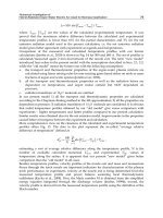
In a recent paper (Rizzo & Sorrentino, 2010), the effects of different strategies of selection of
final SOC are studied by simulation over hourly solar data at different months and
locations, and the benefits achievable by estimating the energy expected in next parking
phase are assessed. The simulations are carried out with a dynamic model of a HSV
previously developed (Arsie et al., 2007), including a rule-based (RB) energy management
strategy. The results have shown that the estimation of the incoming solar energy in next
parking phase produces a more efficient energy management, with reduction in fuel
consumption, particularly at higher insolation (Fig. 13).
Solar Collectors and Panels, Theory and Applications
90
0.3 0.4 0.5 Rule 1 0.6 0.7 0.8 0.9
0
20
40
60
80
100
120
SOC
f
[/]
[kg]
Fuel Consumption - Scenario 2
January
July
Fig. 13. Effects of optimized (Rule 1) and parametric choice of SOC on Fuel Consumption for
a Hybrid Solar Vehicles (Los Angeles, January and July, 1988). ηPV =0.19
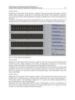
The RB control architecture consists of two loops: i) an external loop, defining the desired
final state of charge to be reached at the end of the driving cycle; ii) an internal loop,
estimating the average power delivered by the internal combustion engine and SOC
deviation. The scheme of rule-based control strategy operation is shown in Fig. 14.
ICE-OFF
ICE-ON
P
EG
SOC
f
P
sun
SOC
P [kW]
P
tr
dSOC
dSOC
Time [min]
SOC
up
SOC
lo
Fig. 14. Schematic representation of the rule-based control strategy for quasi-optimal energy
management of a series HSV powertrain.
The results of RB strategy have been successfully compared with a benchmark (non
implementable) strategy, obtained by means of a Genetic Algorithm (Sorrentino et al., 2009).
In the study, a vehicle dynamic model considering also the effects of engine thermal
transients on fuel consumption and power, related to start-stop operation (Fig. 15), has been
adopted.
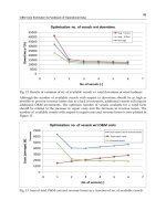
Fig. 16 compares the optimal power of the engine-generator group, operating in start-stop
mode, at various vehicle average power (Rizzo et al., 2010). The red line indicates the most
efficient ICE-EG operating point (PEG,opt), corresponding to about half nominal power.
Such comparison indicates that at high road loads the optimal power values exhibit a load
following behavior, whereas at low power demand they always undergoes PEG,opt. These
results show that, due to the combined effects of engine losses, of thermal transients and of
Hybrid Solar Vehicles
91
0 20 40 60 78
0
25
50
75
100
Time [min]
Engine temperature trajectories [°C] - (b)
Scenario 2
Scenario 3
Fig. 15. Simulated engine temperature profiles in a series hybrid electric vehicle with start-
stop operation.
0 5 10 15 20 25 30
0
10
20
30
40
average P
tr
[kW]
P [kW]
P
EG
rule
P
EG,opt
=21.5 kW
average P
tr
Fig. 16. Optimal generator power vs. average vehicle power for a hybrid electric vehicles
with series structure.
electric losses, the optimal choice of generator power in a series hybrid depends in complex
way from vehicle power, and that optimal engine power corresponds to the maximum
engine efficiency conditions only in a limited power range. A more detailed analysis is
reported in the cited paper (Rizzo et al., 2010).
The importance of thermal transients in start-stop operation over fuel consumption and
emissions, neglected in most models used for energy management in hybrid vehicles, has
been also demonstrated by recent experimental studies (Ohn et al., 2008).
A method for fuel consumption minimization in a Hybrid Solar Vehicle based on
application of Model Predictive Control has also been recently proposed (Preitl et al., 2007).
3.5 Effects of panel position and use of moving roofs
In most of solar cars, solar panels are fixed and located at almost horizontal position. This
solution, although the most practical by several points of view, does not allow to maximize
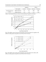
the net power from the sun. In next figure the mean yearly incident energy corresponding to
different position of solar panels is presented, for different latitudes. The data have been
obtained by PVWatts ( based on a database of real data
covering about 30 years, for different locations in USA.
It can be observed that, with the adoption of a self-orienting solar roof (2 axis tracking),
there is an increase of incident energy, varying from about 800 to 600 kWh/m
2
/year, from
low to high latitudes. In terms of relative gain, a moving panel would increase the solar
contribution from about 46%, at low latitudes, up to 78%, at high latitudes. Of course, the
Solar Collectors and Panels, Theory and Applications
92
0
500
1000
1500
2000
2500
3000
0 20406080
2 axis tracking
1 axis tracking
Tilt=Latitude
Horizontal
Vertical (mean)
Latitude (deg)
Mean Yearly Incident Energy (KWh/m
2
/year)
Fig. 17. Effects of panel position and latitude on incident energy
adoption of a moving panel could be feasible only for parking phases, where on the other
hand many cars in urban environment spend most of their time. The real benefits would be
lower than the ones indicated in the graph, due to the energy spent to move the panel and to
possible kinematic constraints preventing perfect orientation. Also, in order to maximize the
solar contribution, transparent panel could be incorporated in the windows, and the lateral
surface of a car could be also covered by solar panels, as for instance in FIAT Phylla. An
estimation of the increase in incident energy can be obtained by considering the mean
incident energy on a vertical surface, with random orientation: with respect to the energy
incident at horizontal position, their contribution is about 45%, at low latitudes, but up to
65% at higher latitudes.
1 2 3 4 5 6 7 8 9 10 11 12
0
10
20
30
40
50
60
70
80
90
100
Month
Normalized energy (%)
LOSANGELES - Lat.33.93
Ideal 2 axis
Moving roof
Horizontal
Fig. 18. Energy collected with various options of solar roof (Los Angeles, 1988)
Hybrid Solar Vehicles
93
It therefore emerges that the adoption of a moving roof for parking phases, and the
utilization of windows and lateral surfaces too, would allow a significant increase of
incident energy with respect to the sole utilization of the car roof. Moreover, this increment
is particularly significant at high latitudes, so contributing to enlarge the potential market of
solar assisted vehicles.
A study on the benefits of a moving solar roof for parking phases in a Hybrid Solar Vehicle
has been recently presented (Coraggio et al., 2010). A kinematic model of a parallel robot
with three degrees of freedom has been developed and validated over the experimental data
obtained by a small scale real prototype. The effects of roof design variables are analyzed,
and the benefits in terms of net available energy assessed by simulation over hourly solar
data at various months and latitudes (Fig. 18).
3.6 Upgrade of conventional vehicles
A possible remark is that, considering the current economic crisis, it is unlikely that, in next
few years, PV assisted EV’s and HEV’s will substitute for a substantial number of
conventional vehicles, since relevant investments on production plants would be needed.
This fact would of course impair the global impact of this innovation on fuel consumption
and CO
2
emissions, at least in a short term scenario. Therefore, one may wonder if there is
any possibility to upgrade conventional vehicles to PV assisted hybrid. A proposal of a kit to
be distributed in after-market has been recently formulated and patented by the author
(www.hysolarkit.com). Mild-solar-hybridization will be performed by installing in-wheel
electric motors on the rear wheels (in case of front wheel drive) and by the integration of
photovoltaic panels on the roof. The original architecture will be upgraded with the an
additional battery pack and a control unit to be faced with the engine management system
by the OBD port. The Vehicle Management Unit (VMU), which would implement control
logics compatible with typical drive styles of conventional-car users, receives the data from
OBD gate and battery (SOC estimation) and drives in-wheel motors by properly acting on
the electric node EN (Fig. 19). A display on the dashboard may advice the driver about the
actual operation of the system. The project has been recently financed by the Italian ministry
of research (www.dimec.unisa.it/PRIN/PRIN_2008.htm). The results will be published
shortly, and presented on the cited websites.
Fig. 19. Scheme of a system to upgrade a conventional car to Mild Hybrid Solar Vehicle.
Solar Collectors and Panels, Theory and Applications
94
4. Conclusion
The integration of photovoltaic panels in hybrid vehicles is becoming more feasible, due to
the increasing fleet electrification, to the increase in fuel costs, to the advances in terms of PV
panel technology, and to the reduction in their cost. Hybrid Solar Vehicles may therefore
represent a valuable solution to face both energy saving and environmental issues. Of
course, these vehicles cannot represent a universal solution, since the best balance between
benefits and costs would depend on mission profile: in particular, significant reductions in
fuel consumption and emissions can be obtained during typical use in urban conditions
during working days. Moreover, the integration with solar energy would also contribute to
reduce battery recharging time, a critical issue for Plug-in vehicles, and to add value for
Vehicle to Grid applications.
Putting a solar panel on an existing hybrid vehicle may be just the first step: in order to
maximize their benefits, re-design and optimization of the whole vehicle-powertrain system
would be required. Particular attention has to be paid in maximizing the net power from
solar panels, and in adopting advanced solutions for power electronics. Moreover, these
vehicle would require specific solutions for energy management and control, whit more
advanced look-ahead capabilities.
The adoption of moving roofs for parking phases and the use of solar panels on windows
and lateral sides would enhance solar contribution, beyond the classical fixed panel on the
car roof. Moreover, these solutions would reduce the gap between solar contribution at low
and high latitudes, so extending the potential market of these vehicles. Interesting
opportunities are also related to possible reconversion of conventional vehicles to Mild
Hybrid Solar Vehicles, by means of kits to be distributed in after-market.
The perspectives about cost issues of hybrid solar vehicles are encouraging. Anyway, as it
happens for many innovations, full economic feasibility could not be immediate, and a
financial support from governments would certainly be appropriate. But the recent and
somewhat unexpected commercial success of some electrical hybrid cars indicates that there
are grounds for hope that a significant number of users is already willing to spend some
more money to contribute to save the planet from pollution, climate changes and resource
depletion.
5. References
Adinolfi G., Arsie I., Di Martino R., Giustiniani A., Petrone G., Rizzo G., Sorrentino M.,
(2008), “A Prototype of Hybrid Solar Vehicle: Simulations and On-Board
Measurements”, Proc.of Advanced Vehicle Control Symposium AVEC 2008,
October 6-9, 2008, Kobe (Japan) 917-922 Society of Automotive Engineers of Japan -
ISBN: 978-4-904056-21-9
Arsie, I., Rizzo, G., Sorrentino, M., (2006) “Optimal Design and Dynamic Simulation of a
Hybrid Solar Vehicle”, SAE paper 2006-01-2997, SAE 2006 Transactions - Journal of
Engines, vol. 115-3, pp. 805-811.
Arsie, I., Rizzo, G., Sorrentino, M., (2010) “Effects of engine thermal transients on the energy
management of series hybrid solar vehicles”, Control Engineering Practice (2010),
DOI:10.1016/j.conengprac.2010.01.015.
Hybrid Solar Vehicles
95
Arsie I, Rizzo G, Sorrentino M (2009) Genetic Algorithms Based Optimization of
Intermittent ICE scheduling on a Hybrid Solar Vehicle In: European Control
Conference 2009, ECC09, Budapest, August 23-26, 2009.
Arsie I., Rizzo G., Sorrentino M. (2008) A Model for the Optimal Design of a Hybrid Solar
Vehicle Review of Automotive Engineering, Society of Automotive Engineers of
Japan (JSAE), 2008, ISSN 1349-4724. 29-3: 439-447
Arsie I., Rizzo G., Sorrentino M. (2007) Optimal Design and Dynamic Simulation of a
Hybrid Solar Vehicle, SAE TRANSACTIONS- JOURNAL OF ENGINES 115-3: 805-
811
Cacciato M., Consoli A., Scarcella G., Testa A. (2004), “A Multhi-Phase DC/DC Converter
for Automotive Dual-voltage Power Systems” IEEE Industry Applications
Magazine, November/December 2004, pp. 2-9.
Cacciato M., Consoli A, Scarcella G, Scelba G. (2007), Accurate Implementation of a State of
Charge Estimator for Hybrid and Elecric Vehicle Battery Packs. 2nd International
Workshop on Hybrid Vehicles. 14 September, 2007. (pp. 1-6). Salerno, Italy.
Coraggio G., Pisanti C., Rizzo G., Sorrentino M. (2010, I), Assessment of benefits obtainable
in a Hybrid Solar Vehicle using look-ahead capabilities for incoming solar energy,
10th Intnl. Symp. On Advanced Vehicle Control, August 22-26, 2010,
Loughborough (UK).
Coraggio G., Pisanti C., Rizzo G., Senatore A. (2010, II), A Moving Solar Roof for a Hybrid
Solar Vehicle, 6th IFAC Symposium on Advances in Automotive Control, July 11-
14, 2010, Munich (D).
Egiziano L., Giustiniani A., Lisi G., Petrone G., Spagnuolo G., Vitelli M.(2007):
“Experimental characterization of the photovoltaic generator for hybrid solar
vehicle”. Proc of 2007 IEEE International Symposium on Industrial Electronics, June
4-7 2007 Vigo (Spain), pp 329-334.
ESA, Electricity Storage Association, www.electricitystorage.org
Femia N., Lisi G., Petrone G., Spagnuolo G., Vitelli M. (2008), “Analysis of Photovoltaic
Systems with Distributed Maximum Power Point Tracking”, Proc. of IEEE
International Symposium on Industrial Electronics ISIE08, June 30-July 2 2008 pp.
2408 - 2413.
Fischer R. (2009), AVL List GmbH, The Electrification of the Powertrain – from Turbohybrid
to Range Extender, 30. Internationales Wiener Motorensymposium 2009
Guzzella L. and Amstutz A. (1999), CAE Tools for Quasi-Static Modeling and Optimization
of Hybrid Poweretrains. IEEE Transactions on Vehicular Technology, vol. 48, no. 6,
November 1999.
Hohm, D.P.; Ropp, M.E., (2000), “Comparative study of maximum power point tracking
algorithms using an experimental, programmable, maximum power point tracking
test bed”, Conference Record of the Twenty-Eighth IEEE Photovoltaic Specialists
Conference, 2000. 15-22 Sept. 2000, pp:1699 – 1702
Jain, A.; Sharma, S.; Kapoor, A., (2006), “Solar cell array parameters using Lambert W-
function”, Solar Energy Materials & Solar Cells 90 (2006) 25–31
Kassakian, J.G. (2000), Automotive Electronics Power Up IEEE Spectrum, Volume: 37, Issue:
5 May 2000, Pages:34 – 39
Kempton W., Tomić J., Letendre S., Brooks A., Lipman T. (2001), “Vehicle-to-Grid Power:
Battery, Hybrid, and Fuel Cell Vehicles as Resources for Distributed Electric Power
Solar Collectors and Panels, Theory and Applications
96
in California”, Report prepared for California Air Resources Board and the
California Environmental Protection Agency, 2001.
Letendre S., Perez R., Herig C. (2003), Vehicle Integrated PV: A Clean and Secure Fuel for
Hybrid Electric Vehicles, Proc. of the American Solar Energy Society Solar 2003
Conference, June 21-23, 2003, Austin,TX.
Liu, S., Dougal, R.A. (2002), ”Dynamic multiphysics model for solar array”, IEEE Trans. On
Energy Conversion, Vol. 17, No. 2, June 2002, pp. 285-294.
Neil C. (2006), Solar Hybrid Vehicles,
Preitl Z., Bauer P., Kulcsar B., Rizzo G., Bokor J. (2007), Control Solutions for Hybrid Solar
Vehicle Fuel Consumption Minimization In: Proceedings of the 2007 IEEE
Intelligent Vehicles Symposium, Istanbul, Turkey, June 13-15, 2007.
Quaschning V. (2003), "Technology fundamentals - The sun as an energy resource".
Renewable Energy World 6 (5): 90–93.
REN21, Renewables - Global Status Report - 2009 Update,
Rizzo G., (2010), Automotive Applications of Solar Energy, 6th IFAC Symposium on
Advances in Automotive Control, July 11-14, 2010, Munich (D).
Rizzo G., Sorrentino M., (2010), Introducing Sunshine Forecast to Improve On-Board Energy
Management of Hybrid Solar Vehicles, 6th IFAC Symposium on Advances in
Automotive Control, July 11-14, 2010, Munich (D).
Segal A., Epstein M., Yogev A., (2004), Hybrid concentrated photovoltaic and thermal power
conversion at different spectral bands, Solar Energy 76 (2004) 591–601
Smil V., (2006), Energy at the Crossroads, Global Science Forum Conference on Scientific
Challenges for Energy Research, Paris, May 17-18, 2006,
Statistics for Road Transport, UK Government,
Thilagam, A., Singh, J., Stulik, P., (1998), Optimizing Gallium Arsenide multiple quantum
wells as high-performance photovoltaic devices, Solar Energy Materials and Solar
Cells, Vol: 50, 1-4, January, 1998 pp. 243-249, Elsevier
5
Degradation of Space Exposed Surfaces by
Hypervelocity Dust Bombardment – Example:
Solar Cell Samples
H. M. Ortner
1,2
1
Darmstadt University of Technology, Dept.of Materials Science,
2
Present address: Osterbichl 16, A 6600 Breitenwang,
1
Germany
2
Austria
1. Introduction
The analysis of cosmic particles by secondary ion mass spectrometry (SIMS) has developed
into an essential tool of cosmophysics and –chemistry as well as of applied space-research.
This way it is feasible to gain important information about the origin, the evolution and the
structure of our solar system (Brownlee, 1978; Grün et al., 2001). In addition, the
discrimination between terrestrial and cosmic particles is critical for an estimate of damage
of space exposed surfaces by the impact of such particles. This is especially important for the
multitude of satellites in near-earth space, i.e. in low earth orbits, fig.1.
Fig. 1. Draft of a satellite orbit in 500 km altitude
Solar Collectors and Panels, Theory and Applications
98
Low earth orbits (LEO), i. e. the altitude between 180 and 650 kilometers above the earth’s
surface, is one of the busiest traffic zones in space. Nevertheless, the conditions in LEO are
harsh. It is a region of intensive hard UV-radiation and the little oxygen still present from
the earth’s atmosphere is highly-reactive atomic oxygen. It is also a region of high
temperature variations between -100°C to +100°C and, as will be discussed in more detail
later, a region full of manmade space debris –in addition to cosmic dust micrometeorites
(Murr & Kinard, 1993)
Particles are travelling there with velocities of around 10 km/s. If they hit material surfaces
they almost completely evaporate due to their high impact velocity and cause the formation
of a crater, which is up to one order of magnitude larger than the impacting particle, fig.2.
Fig. 2. SEM-micrograph of an impact crater on a germanium surface caused by a cosmic dust
particle. In order to clearly differentiate between ions generated from material and such of
the impacted particle in SIMS-analysis, it is advantageous to use rather exotic and highly
pure substrates such as gold or germanium. The particles scattered around the impact crater
are Ge-particles and not remnants of the impacted cosmic particle which evaporated
completely. Only extreme traces of its matter are detectable by SIMS.
This turns out to be a serious problem for space technology because the impact of a
multitude of such particles will quickly deteriorate space exposed surfaces. The mean life
time e.g. of solar panels for the generation of energy for satellites is thus seriously reduced.
Degradation of Space Exposed Surfaces by
Hypervelocity Dust Bombardment – Example: Solar Cell Samples
99
2. Cosmic dust: An essential part of matter in the universe
The investigation of cosmic dust particles has thus developed to an interesting and
fascinating area of cosmophysics and –chemistry (Stadermann, 1992). Cosmic dust
constitutes an essential part of matter in the universe. The earliest hint of the existence of
dust in our solar system came from the observation of the zodiacal light. This can be
observed with bare eye shortly before sunrise or shortly after sunset, over the Eastern or
Western horizon, respectively. Already in the 18
th
century, Cassini interpreted this Zodiacal
light as light-reflection and – scatter caused by a giant cloud of dust particles in the ecliptic.
Today, it is known from spectroscopic investigations of the reflected sun light that these
dust particles have diameters between 0.1 and 100 µm. The zodiacal dust cloud exhibits the
form of a flat disk and extends over the whole inner range of the solar system.
From theoretical considerations it is known that the dust particles of this cloud do not move
on Kepler-orbits around the sun but instead move on spiral orbits into the sun (Stadermann,
1992). This “Poynting-Robertson -Effect” is caused by a retardation of orbiting particles by
an interaction with the solar radiation. For a 10 µm particle the life time is limited to about
100,000 years before it is burned up in the sun. Some are also trapped by the earth’s gravity
and may enter its atmosphere. Cosmic particles up to about 50 µm can efficiently radiate
away the heat which is generated by their slowing down in the earth’s atmosphere due to
friction. Greater particles cannot do this effectively enough and hence, burn up in the upper
layers of the atmosphere. This leads to the apparent paradox that microscopic dust particles
as well as meteorites as big as one’s fist survive the entrance into the earth’s atmosphere
while particles of the size of a grain of sand burn as shooting stars. The macroscopic
meteorites survive their travel through the atmosphere because of a totally different reason:
They fall so quickly that their inner part does not heat up while only their outer layers
evaporate. Once decelerated from cosmic velocities, the cosmic dust particles which are of
prime interest to us take a long time for their trip from the earth’s outer atmosphere to the
earth’s surface: depending on atmospheric conditions (wind, weather) this part of their trip
can last several months. They usually endure this travel relatively sound and this is the
reason why our planet is daily gaining several tons due to the trapping of extraterrestrial
material (Stadermann, 1992). This gain in part is counterbalanced by a loss of hydrogen,
helium, atomic oxygen and possibly carbon (mainly as methane) in the exosphere as a result
of non-thermal escape mechanisms (Shizgal & Arkos, 1996)
3. Problems with sampling of interplanetary dust
The seemingly simplest way – the direct collection of cosmic dust in space with a dedicated
space exposed device is in practice rather problematic. The problem is the high velocity of
several km/s with which these particles travel. If they hit a collecting device without
deceleration they almost completely evaporate in fractions of a second. A part of the
evaporated material will condense around the crater which is formed upon the particle
impact while only a minor fraction of the original projectile will survive the impact as debris
inside the crater, fig.2.
An ideal collector for cosmic dust particles would gently decelerate the often fragile
particles. And this is exactly what happens in the outer realms of the earth’s atmosphere.
Eventually, the particles are sedimenting down with quite low velocities. Interestingly this
also causes a density of cosmic particles in the earth’s atmosphere that is many orders of
Solar Collectors and Panels, Theory and Applications
100
magnitude higher than in space. In order to prevent a mixing of cosmic particles with
terrestrial aerosols the sampling has to be carried out in the stratosphere. In the 1960s it was
tried to collect cosmic dust with high flying balloons. However, the yield was very modest.
Therefore, NASA initiated a program in the 1970s in which cosmic dust was collected with
U2-planes flying in the stratosphere (Stadermann 1992). For this purpose, palm sized
collecting surfaces have been prepared which were coated with silicon oil. These collecting
surfaces were exposed to the air stream of planes travelling at an altitude of 20 km (twice as
high as most commercial traffic) beneath a wing of the plane for several hours. Nevertheless,
only a single particle greater than 5 µm is caught per hour. Of these very few collected
particles in the clean surrounding every second particle is still of terrestrial origin. Often ash
particles from volcanic eruptions are found which had been injected into the stratosphere.
Hence, after greater volcanic eruptions (as, e. g. of the Pinatubo in 1991) the collection of
cosmic dust in the stratosphere has to be discontinued for several months because the
volcanic dust cloud is dispersed quickly and thoroughly around the earth.
It goes without mentioning that during sample preparation and investigation no additional
contamination can be tolerated, work has to be performed under strict cleanroom conditions
and, due to the dust grain size, mostly under the microscope. Hence, particles are removed
one by one from the collector surface and subsequently cleaned from the silicon oil. They are
thereby viewed in the light microscope. Afterwards they are characterized closer in the
scanning electron microscope (SEM). Fig. 3 shows some typical particle morphologies of
extraterrestrial particles.
Modern new detection systems for hypervelocity microparticles using piezoelectric material
have rather recently been developed (Miyachi et al., 2004). Furthermore, a dust cloud of
Ganymede has also been detected by in situ measurements with the dust detector onboard
the Galileo spacecraft (Krüger et al., 2000).
4. Secondary Ion Mass Spectrometry (SIMS) – the key instrumentation for
cosmic dust analysis
It is difficult to gain information on the nature of impacting particles due to the fact that
most of the particle matter is evaporating during the impact. The minute amounts of particle
matter which remain on the material surface in and around the impact crater can only be
detected by a very sensitive method of topochemical analysis. SIMS is the topochemical
method with the highest detection sensitivity and, hence, it is the method of choice for such
investigations. In addition, the ability of SIMS to distinguish between various isotopes of an
element is the key to differentiate between terrestrial and cosmic particles (Stadermann,
1990). It has been observed in LEO that the most serious degradation is caused by terrestrial
aluminium oxide particles (Corso, 1985). The origin of such particles was a solid rocket fuel
(Al-powder) which was used by one of the nation’s leading in space technology. It was
finally feasible to ban this technology in favour of liquid fuels for rocket propulsion which
do not generate Al
2
O
3
-particles. The outstanding significance of SIMS for such
investigations consequently led to the development of the NanoSIMS (Schuhmacher et al.,
1999) which exhibits a dramatically improved lateral resolution in the ten-nanometer
domain (as compared to a lateral resolution in the single µm-range for a conventional SIMS
instrument). It also has a multi-detection system which is important since the amount of
material to be sputtered is very limited in this special application, fig.4.
Degradation of Space Exposed Surfaces by
Hypervelocity Dust Bombardment – Example: Solar Cell Samples
101
3a. Spherical particle. Main elemental
composition: Mg, Si, O (traces Ca, Fe).The
morphology of the particle indicates that it
once was in a realm where the temperature
was higher than its melting temperature.
Another possibility would be the emission
from a melt.
3b. This particle seems to be a
conglomerate of smaller particles. Main
elemental components: Mg, O (N, C, H).
3c. Precipitate of an LDEF impact on
germanium. The broad dark stripe is the
trace of the ion beam with which the
analysis was carried out.
3d. Particle storage sheet of Stadermann
Fig. 3. SEM-micrographs of some typical particle morphologies of extraterrestrial particles
(Stadermann, 1990)
Solar Collectors and Panels, Theory and Applications
102
Fig. 4a shows the ion optical system of the NanoSIMS of CAMECA (Courtesy of CAMECA,
Paris). Fig. 4b shows the NanoSIMS 50 installed in the laboratory of the Physics Dept. at
Washington University in St. Louis
Fig. 4a. The NanoSIMS 50 of CAMECA (Courtesy of CAMECA, Paris)
Degradation of Space Exposed Surfaces by
Hypervelocity Dust Bombardment – Example: Solar Cell Samples
103
Fig. 4b. The NanoSIMS 50 in the laboratory of the Washington Univ., Physics Dept., St.
Louis, MO, USA
The impact crater of fig. 2 demonstrates impressively how space exposed surfaces
eventually deteriorate by impact of many such particles.
5. The significance of material degradation of space exposed surfaces – the
LDEF experiment
This has alarmed the American National Aeronautics and Space Administration (NASA) to
an extent that a respective materials degradation experiment was organized, the LDEF-
experiment (Long Duration Exposure Facility). The heart of this action was a large
cylindrical satellite with a length of 9 m which is shown in fig. 5.
This satellite was of the size of a bus and was brought into a Low Earth Orbit in an altitude
of 476 km in 1984 (Murr & Kinard, 1993). It contained more than 10,000 test material plates
which were exposed to the rather unfriendly environment of the LEO for degradation
studies. These surfaces were exposed to bombardment by micrometeorites and near-earth
space debris of man-made origin which led to a deterioration of the plates’ surfaces. The
LDEF day was only 90 min long as well as its night. With this frequency, the temperature
varied from +100°C to -100°C! In addition during sunshine a most intensive UV-radiation
was also hitting the surface. This effect combined with atomic oxygen (Atox) which is also
present due to the last traces of the earth’s atmosphere in this altitude. The combined action
of these influences resulted in interesting corrosion and erosion phenomena (Murr &
Solar Collectors and Panels, Theory and Applications
104
Fig. 5. View of the LDEF-experiment exposed in LEO (Courtesy of NASA Langley Research
Center)
Kinard, 1993). The satellite was not retrieved after the planned exposure time due to the
Challenger disaster. Only in 1990 after 34,000 earth orbits in 2105 days the LDEF-experiment
was retrieved in the last possible moment by the Space Shuttle, fig. 6. It was taken into the
shuttle in an altitude of only 333 km shortly before the satellite would have burned down in
the upper atmosphere.
However, due to its very long exposure time, corrosion and erosion phenomena were very
pronounced and a lot of interesting and alarming observations were made (Mandeville,
1991). One of the most alarming finds was that more than 80% of all investigated particle
impact craters by SIMS turned out to be caused by terrestrial (man-made) and not by cosmic
particles. The highest percentage of these particles was Al
2
O
3
-particles stemming from solid
state rocket fuels. This was the reason why Russia finally changed over to liquid fuel
systems. However, not only Al
2
O
3
-particles of terrestrial origin had been detected.
Titanium- and cadmium-rich particles were also registered. They originated from paints
with which rocket surfaces had been painted. Particles of stainless steel, mineral particles
and such of silver-solder had also been detected (Murr α Kinard, 1993). The geometry of the
impact craters of particles allowed calculations of the velocity of impacting particles. SIMS-
results on the composition of extraterrestrial particles yielded another interesting detail:
Many analyzed cosmic particles exhibited nearly the same composition as so called
chondritic (C1) meteorites (main constituents: Si, Al, Mg, Fe, Ca, O) (Stadermann, 1990). It is
believed that the solar nebula from which our solar system developed 4.5 billion years ago
had the same chondritic composition. Eventually the planets and other bodies developed,
the composition of which varies considerably and deviates from this original composition
because of diverse chemical processes (so called fractionations). However, material with
chondritic composition is still found in some meteorites and many cosmic dust particles.
This is an indication that these objects are of “primitive” nature, i. e. very old and
unchanged material (Stadermann, 1992).
Degradation of Space Exposed Surfaces by
Hypervelocity Dust Bombardment – Example: Solar Cell Samples
105
Fig. 6. Recovery of the LDEF-experiment from LEO.
6. Rocket and other space debris: mortal danger in near Earth space
It must be mentioned that surface erosion by cosmic dust is not the only danger of material
degradation in space. Especially near the earth, there is eminent danger of collision with
much greater “particles” of space debris. The reason is a rising number of debris items with
more than 10 cm diameter, mainly rocket parts and abandoned satellites which all circle
around the earth with about 36 000 km/h. Another 100 000 parts with diameters between 1
and 10 centimeters and another billion of parts with diameters below 1 cm complete this
symphony of danger for space vehicles near the earth (Spiegel, 1995). Among the very small
parts are also minispheres of human debris which were ejected from space vehicles. It goes
without saying that a collision with such parts can cause heavy damage of a satellite or a
space vehicle. In November 1995 the US space Shuttle “Columbia” was hit by a small part –
presumably an electronic structural part. After return to earth an impact crater of six
millimeters in depth and two centimeters in diameter was detected in the hatchway of the
shuttle. If this part would have hit the oxygen tank of the shuttle an explosion would have
been inevitable. Since it is to be expected that the number of such parts will rise in near earth
space it could be that in a couple of years a safe travel of space vehicles in this region will
not be possible any more (Spiegel, 1995, Schmundt, 2003). This would cause a throwback of
mankind into a technological “stone age”. If used up satellites can no longer be replaced,
satellite television, GPS, wireless global phone calls, and many other services of today will
cease to operate. Hence LEO has become something like an international waste disposal.
Well over 150 000 scrap parts of earlier space missions race around the earth: Old and
inoperable satellites, rocket parts, diverse metal parts, astronauts gloves, metal tools etc.
(Schmundt, 2003). They have become the primary danger for space flights in LEO. No