Advances in Robot Manipulators Part 1 pot
Bạn đang xem bản rút gọn của tài liệu. Xem và tải ngay bản đầy đủ của tài liệu tại đây (2.38 MB, 40 trang )
I
Advances in Robot Manipulators
Advances in Robot Manipulators
Edited by
Ernest Hall
In-Tech
intechweb.org
Published by In-Teh
In-Teh
Olajnica 19/2, 32000 Vukovar, Croatia
Abstracting and non-prot use of the material is permitted with credit to the source. Statements and
opinions expressed in the chapters are these of the individual contributors and not necessarily those of
the editors or publisher. No responsibility is accepted for the accuracy of information contained in the
published articles. Publisher assumes no responsibility liability for any damage or injury to persons or
property arising out of the use of any materials, instructions, methods or ideas contained inside. After
this work has been published by the In-Teh, authors have the right to republish it, in whole or part, in any
publication of which they are an author or editor, and the make other personal use of the work.
© 2010 In-teh
www.intechweb.org
Additional copies can be obtained from:
First published April 2010
Printed in India
Technical Editor: Sonja Mujacic
Cover designed by Dino Smrekar
Advances in Robot Manipulators,
Edited by Ernest Hall
p. cm.
ISBN 978-953-307-070-4
V
Preface
The purpose of this volume in Advances in Robot Manipulators is to encourage and inspire
the continual invention of robot manipulators for science and the good of humanity. The
concepts of articial intelligence combined with the engineering and technology of feedback
control, have great potential for new, useful and exciting machines. The concept of eclecticism
for the design, development, simulation and implementation of a real time controller for an
intelligent, vision guided robots is now being explored. The dream of an eclectic perceptual,
creative controller that can select its own tasks and perform autonomous operations with
reliability and dependability is starting to evolve. We have not yet reached this stage but a
careful study of the contents will start one on the exciting journey that could lead to many
inventions and successful solutions.
Editor:
Ernest Hall
VI
VII
Contents
Preface V
1. ABiomimeticsteeringrobotforMinimallyinvasivesurgeryapplication 001
G.Chen,M.T.Pham,T.Maalej,H.Fourati,R.MoreauandS.Sesmat
2. ARegressor-freeAdaptiveControlforFlexible-jointRobotsbasedonFunction
ApproximationTechnique 027
Ming-ChihChienandAn-ChyauHuang
3. A9-DoFWheelchair-MountedRoboticArmSystem:Design,Control,
Brain-ComputerInterfacing,andTesting 051
RedwanAlqasemiandRajivDubey
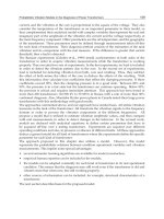
4. AdvancedTechniquesofIndustrialRobotProgramming 079
FrankShaopengCheng
5. AnOpen-architectureRobotControllerappliedtoInteractionTasks 099
A.Oliveira,E.DePieriandU.Moreno
6. CollaborationPlanningbyTaskAnalysisinHuman-Robot
CollaborativeManufacturingSystem 113
JeffreyTooChuanTan,FengDuan,RyuKatoandTamioArai
7. Collaborativerulesoperatingmanipulators 133
JoséMartinsJunior,LuizCamolesiJrandGlaucoAugustodePaulaCaurin
8. ControlofLightweightManipulatorsBasedonSlidingModeTechnique 155
JingxinShi,FengleiNiandHongLiu
9. CoordinateTransformationBasedContourFollowingControl
forRoboticSystems 183
Chieh-LiChenandChao-ChungPeng
10. DesignofAdaptiveControllersbasedonChristoffelSymbolsofFirstKind 205
JuanIgnacioMulero-Martínez
11. DevelopmentofaNew2DOFLightweightWristfortheHumanoid
RobotARMAR 237
AlbertAlbers,JensOttnadandChristianSander
VIII
12. DevelopmentofTendonBasedDexterousRobotHand 255
Chung-HsienKuoandChun-TzuChen
13. DimensionalSynthesisandAnalysisofthe2-UPS-PUParallelManipulator 267
YunfengZhaoYanhuaTangYongshengZhao
14. DirectandIndirectAdaptiveFuzzyControlforaClassofMIMO
NonlinearSystems 279
SalimLabiodandThierryMarieGuerra,
15. DynamicTrajectory-TrackingControlofanOmnidirectionalMobile
RobotBasedonaPassiveApproach 299
M.Velasco-Villa,H.Rodríguez-Cortés,I.Estrada-Sanchez,
H.Sira-RamírezandJ.A.Vázquez
16. EclecticTheoryofIntelligentRobots 315
E.L.Hall,S.M.AlhajAli,M.Ghaffari,X.LiaoandMingCao
17. Enhancedstiffnessmodelingofserialmanipulatorswithpassivejoints 331
AnatolPashkevich,AlexandrKlimchikandDamienChablat
18. FastDynamicModelofaMoving-base6-DOFParallelManipulator 361
AntónioM.Lopes
19. ImprovingthePoseAccuracyofPlanarParallelRobotsusing
MechanismsofVariableGeometry 381
JensKotlarski,BodoHeimannandTobiasOrtmaier
20. KinematicSingularitiesofRobotManipulators 401
PeterDonelan
21. MotionControlofIndustrialRobotsinOperationalSpace:
AnalysisandExperimentswiththePA10Arm 417
RicardoCampa,CésarRamírez,KarlaCamarillo,VíctorSantibáñezandIsraelSoto
22. MRICompatibleRobotSystemsforMedicalIntervention 443
MingLi,DumitruMazilu,AnkurKapoorandKeithA.Horvath
23. OntheOptimalSingularity-FreeTrajectoryPlanningofParallel
RobotManipulators 459
Chun-TaChenandTe-TanLiao
24. Programming-by-DemonstrationofReachingMotionsusing
aNext-State-Planner 479
AlexanderSkoglund,BoykoIlievandRainerPalm
25. RobotArmswith3DVisionCapabilities 503
TheodorBorangiuandAlexandruDumitrache
26. Robotassisted3Dshapeacquisitionbyopticalsystems 515
CesareRossi,VincenzoNiola,SergioSavinoandSalvatoreStrano
IX
27. ROBUSTCONTROLDESIGNFORTWO-LINKNONLINEAR
ROBOTICSYSTEM 551
ShieldB.LinandSheng-GuoWang
28. RoleofFiniteElementAnalysisinDesigningMulti-axesPositioningforRobotic
Manipulators 565
T.T.Mon,F.R.MohdRomlayandM.N.Tamin
29. StatisticalImitationLearninginSequentialObjectManipulationTasks 589
KomeiSugiura,NaotoIwahashi,HidekiKashiokaandSatoshiNakamura
30. Tangibleinterfacesfortangiblerobots 607
AndrewCyrusSmith
31. TimoshenkoBeamTheorybasedDynamicModelingofLightweightFlexibleLink
RoboticManipulators 625
MalikLoudini
32. TrajectoryControlofRLEDRobotManipulatorsUsingaNewType
ofLearningRule 651
HüseyinCanbolat
X
ABiomimeticsteeringrobotforMinimallyinvasivesurgeryapplication 1
ABiomimeticsteeringrobotforMinimallyinvasivesurgeryapplication
G.Chen,M.T.Pham,T.Maalej,H.Fourati,R.MoreauandS.Sesmat
0
A Biomimetic steering robot for
Minimally invasive surgery application
G. Chen*
Unilever R&D, Port Sunlight
United Kingdom
M.T. Pham, T. Maalej, H. Fourati,
R. Moreau and S. Sesmat
Laboratoire Ampère, UMR CNRS 5005,
INSA-Lyon, Université de Lyon, F-69621
France
Abstract
Minimally Invasive Surgery represents the future of many types of medical interventions such
as keyhole neurosurgey or transluminal endoscopic surgery. These procedures involve inser-
tion of surgical instruments such as needles and endoscopes into human body through small
incision/ body cavity for biopsy and drug delivery. However, nearly all surgical instruments
for these procedures are inserted manually and there is a long learning curve for surgeons to
use them properly. Many research efforts have been made to design active instruments (endo-
scope, needles) to improve this procedure during last decades. New robot mechanisms have
been designed and used to improve the dexterity of current endoscope. Usually these robots
are flexible and can pass the constrained space for fine manipulations. In recent years, a con-
tinuum robotic mechanism has been investigated and designed for medical surgery. Those
robots are characterized by the fact that their mechanical components do not have rigid links
and discrete joints in contrast with traditional robot manipulators. The design of these robots
is inspired by movements of animals’ parts such as tongues, elephant trunks and tentacles.
The unusual compliance and redundant degrees of freedom of these robots provide strong
potential to achieve delicate tasks successfully even in cluttered and unstructured environ-
ments. This chapter will present a complete application of a continuum robot for Minimally
Invasive Surgery of colonoscopy. This system is composed of a micro-robotic tip, a set of po-
sition sensors and a real-time control system for guiding the exploration of colon. Details will
be described on the modeling of the used pneumatic actuators, the design of the mechanical
component, the kinematic model analysis and the control strategy for automatically guiding
the progression of the device inside the human colon. Experimental results will be presented
to check the performances of the whole system within a transparent tube.
* Corresponding author.
1
AdvancesinRobotManipulators2
1. Introduction
Robotics has increasingly become accepted in the past 20 years as a viable solution to many
applications in surgery, particularly in the field of Minimally Invasive Surgery (MIS)Taylor &
Stoianovici (2003). Minimally Invasive Surgery represents the future of many types of medical
interventions such as keyhole neurosurgery or transluminal endoscopic surgery. These pro-
cedures involve insertion of surgical instruments such as needles and endoscopes into human
body through small incision/ body cavity for biopsy and drug delivery. However, nearly all
surgical instruments for these procedures are inserted manually and they are lack of dexterity
in small constrained spaces. As a consequence, there is a long learning curve for surgeons to
use them properly and thus risks for patients. Many research efforts have been made to im-
prove the functionalities of current instruments by designing active instruments (endoscope,
needles) using robotic mechanisms during the last decades, such as snake robot for throat
surgery Simaan et al. (2004) or active cannula Webster et al. (2009). Studies are currently un-
derway to evaluate the value of these new devices. Usually these robots are micro size and
very flexible so that they can pass the constrained space for fine manipulations. Furthermore,
how to steer these robots into targets safely during the insertion usually needs additional sen-
sors, such as MRI imaging and US imaging, and path planning algorithms are also needed to
be developed for the intervention.
Colonoscopy is a typical MIS procedure that needs the insertion of long endoscope inside
the human colon for diagnostics and therapy of the lower gastrointestinal tract including the
colon. The difficulty of the insertion of colonoscope into the human colon and the pain of the
intervention brought to the patient hinders the diagnostics of colon cancer massively. This
chapter will present a novel steerable robot and guidance control strategy for colonoscopy
interventions which reduces the challenge associated with reaching the target.
1.1 Colonoscopy
Today, colon cancer is an increasing medical concern in the world, where the second frequent
malignant tumor is found in industrialized countries Dario et al. (1999). There are several
different solutions to detect this kind of cancer, but only colonoscopy can not only make diag-
nostics, but make therapy. Colonoscopy is a procedure which is characterized by insertion of
endoscopes into the human colon for inspection of the lower gastrointestinal tract including
the colon in order to stop or to slow the progression of the illness. The anatomy of the colon
is showed in Fig. 1.
The instrument used for diagnostics and operation of the human colon is called endoscope
(also colonoscope) which is about 1.5cm in diameter and from 1.6 to 2 meters in length.
Colonoscopy is one of the most technically demanding endoscopic examinations and tends
to be very unpopular with patients because of many sharp bends and constrained workspace.
The main reason lies in the characteristics of current colonoscopes, which are quite rigid and
require the doctor to perform difficult manoeuvres for long insertion with minimal damage of
the colon wall Fukuda et al. (1994); Sturges (1993).
1.2 State of the art: Robotic colonoscopy
Since the human colon is a tortuous “tube” with several sharp bends, the insertion of the
colonoscope requires the doctor to exert forces and rotations at shaft outside of the patient,
thus causing discomfort to the patient. The complexity of the procedure for doctors and
the discomfort experienced by the patient of current colonoscopies lead many researchers
to choose the automated colonoscopy method. In Phee et al. (1998), the authors proposed the
Fig. 1. The anatomy of the colon
concept of automated colonoscopy (also called robotic colonoscopy) from two aspects: loco-
motion and steering of the distal end, which are the two main actions during a colonoscopy. In
order to facilitate the operation of colonoscopy, some studies on the robotic colonoscopy have
been carried out from these two aspects. Most current research on autonomous colonoscopies
have been focused on the self-propelled robots which utilize various locomotion mecha-
nisms Dario et al. (1997); Ikuta et al. (1988); Kassim et al. (2003); Kumar et al. (2000); Menci-
assi et al. (2002); Slatkin & Burdick (1995). Among them, inchworm-like locomotion attracted
much more attention Dario et al. (1997); Kumar et al. (2000); Menciassi et al. (2002); Slatkin
& Burdick (1995). However, most of the current inchworm-based robotic systems Dario et al.
(1997); Kumar et al. (2000); Menciassi et al. (2002); Slatkin & Burdick (1995) showed low effi-
ciency of locomotion for exploring the colon because of the structure of the colon wall: slip-
pery and different diameters at each section.Another aspect work that could improve the per-
formance of current colonoscopies is to design an autonomous steering robot for guidance
inside the colon during the colonoscopy. Fukuda et al. (1994) proposed Shape Memory Alloy
(SMA) based bending devices, called as Micro-Active Catheter (MAC), with two degrees of
freedom. With three MACs connected together in series, an angle of bend of nearly 80
◦
is
possible. In Menciassi et al. (2002), a bendable tip has been also designed and fabricated by
using a silicone bellows with a length of 30mm. It contains three small SMA springs with a
120
◦
layout. This device allows a 90
o
bending in three directions. These flexible steering tips
are the only parts of the whole self-propelling robots, however those works did not focus on
how to control this special robot to endow it with a capability for autonomous guidance Kim
et al. (2006); Kumar et al. (2000); Menciassi et al. (2002); Piers et al. (2003). Since 2001, there is
another method to perform colon diagnostics: capsule endoscopy (n.d.a;n). With a camera, a
light source, a transmitter and power supply integrated into a capsule, the patient can swallow
and repel it through natural peristalsis without any pain. Despite capsule endoscopy advan-
tages, it does not allow to perform the diagnostics more thoroughly and actively. Recently,
different active locomotion mechanisms have been investigated and designed to address this
problem, such as clamping mechanism Menciassi et al. (2005), SMA-based Gorini et al. (2006);
ABiomimeticsteeringrobotforMinimallyinvasivesurgeryapplication 3
1. Introduction
Robotics has increasingly become accepted in the past 20 years as a viable solution to many
applications in surgery, particularly in the field of Minimally Invasive Surgery (MIS)Taylor &
Stoianovici (2003). Minimally Invasive Surgery represents the future of many types of medical
interventions such as keyhole neurosurgery or transluminal endoscopic surgery. These pro-
cedures involve insertion of surgical instruments such as needles and endoscopes into human
body through small incision/ body cavity for biopsy and drug delivery. However, nearly all
surgical instruments for these procedures are inserted manually and they are lack of dexterity
in small constrained spaces. As a consequence, there is a long learning curve for surgeons to
use them properly and thus risks for patients. Many research efforts have been made to im-
prove the functionalities of current instruments by designing active instruments (endoscope,
needles) using robotic mechanisms during the last decades, such as snake robot for throat
surgery Simaan et al. (2004) or active cannula Webster et al. (2009). Studies are currently un-
derway to evaluate the value of these new devices. Usually these robots are micro size and
very flexible so that they can pass the constrained space for fine manipulations. Furthermore,
how to steer these robots into targets safely during the insertion usually needs additional sen-
sors, such as MRI imaging and US imaging, and path planning algorithms are also needed to
be developed for the intervention.
Colonoscopy is a typical MIS procedure that needs the insertion of long endoscope inside
the human colon for diagnostics and therapy of the lower gastrointestinal tract including the
colon. The difficulty of the insertion of colonoscope into the human colon and the pain of the
intervention brought to the patient hinders the diagnostics of colon cancer massively. This
chapter will present a novel steerable robot and guidance control strategy for colonoscopy
interventions which reduces the challenge associated with reaching the target.
1.1 Colonoscopy
Today, colon cancer is an increasing medical concern in the world, where the second frequent
malignant tumor is found in industrialized countries Dario et al. (1999). There are several
different solutions to detect this kind of cancer, but only colonoscopy can not only make diag-
nostics, but make therapy. Colonoscopy is a procedure which is characterized by insertion of
endoscopes into the human colon for inspection of the lower gastrointestinal tract including
the colon in order to stop or to slow the progression of the illness. The anatomy of the colon
is showed in Fig. 1.
The instrument used for diagnostics and operation of the human colon is called endoscope
(also colonoscope) which is about 1.5cm in diameter and from 1.6 to 2 meters in length.
Colonoscopy is one of the most technically demanding endoscopic examinations and tends
to be very unpopular with patients because of many sharp bends and constrained workspace.
The main reason lies in the characteristics of current colonoscopes, which are quite rigid and
require the doctor to perform difficult manoeuvres for long insertion with minimal damage of
the colon wall Fukuda et al. (1994); Sturges (1993).
1.2 State of the art: Robotic colonoscopy
Since the human colon is a tortuous “tube” with several sharp bends, the insertion of the
colonoscope requires the doctor to exert forces and rotations at shaft outside of the patient,
thus causing discomfort to the patient. The complexity of the procedure for doctors and
the discomfort experienced by the patient of current colonoscopies lead many researchers
to choose the automated colonoscopy method. In Phee et al. (1998), the authors proposed the
Fig. 1. The anatomy of the colon
concept of automated colonoscopy (also called robotic colonoscopy) from two aspects: loco-
motion and steering of the distal end, which are the two main actions during a colonoscopy. In
order to facilitate the operation of colonoscopy, some studies on the robotic colonoscopy have
been carried out from these two aspects. Most current research on autonomous colonoscopies
have been focused on the self-propelled robots which utilize various locomotion mecha-
nisms Dario et al. (1997); Ikuta et al. (1988); Kassim et al. (2003); Kumar et al. (2000); Menci-
assi et al. (2002); Slatkin & Burdick (1995). Among them, inchworm-like locomotion attracted
much more attention Dario et al. (1997); Kumar et al. (2000); Menciassi et al. (2002); Slatkin
& Burdick (1995). However, most of the current inchworm-based robotic systems Dario et al.
(1997); Kumar et al. (2000); Menciassi et al. (2002); Slatkin & Burdick (1995) showed low effi-
ciency of locomotion for exploring the colon because of the structure of the colon wall: slip-
pery and different diameters at each section.Another aspect work that could improve the per-
formance of current colonoscopies is to design an autonomous steering robot for guidance
inside the colon during the colonoscopy. Fukuda et al. (1994) proposed Shape Memory Alloy
(SMA) based bending devices, called as Micro-Active Catheter (MAC), with two degrees of
freedom. With three MACs connected together in series, an angle of bend of nearly 80
◦
is
possible. In Menciassi et al. (2002), a bendable tip has been also designed and fabricated by
using a silicone bellows with a length of 30mm. It contains three small SMA springs with a
120
◦
layout. This device allows a 90
o
bending in three directions. These flexible steering tips
are the only parts of the whole self-propelling robots, however those works did not focus on
how to control this special robot to endow it with a capability for autonomous guidance Kim
et al. (2006); Kumar et al. (2000); Menciassi et al. (2002); Piers et al. (2003). Since 2001, there is
another method to perform colon diagnostics: capsule endoscopy (n.d.a;n). With a camera, a
light source, a transmitter and power supply integrated into a capsule, the patient can swallow
and repel it through natural peristalsis without any pain. Despite capsule endoscopy advan-
tages, it does not allow to perform the diagnostics more thoroughly and actively. Recently,
different active locomotion mechanisms have been investigated and designed to address this
problem, such as clamping mechanism Menciassi et al. (2005), SMA-based Gorini et al. (2006);
AdvancesinRobotManipulators4
Kim et al. (2005), magnet-based Wang & Meng (2008) locomotion and biomimetic geckoGlass
et al. (2008) .
1.3 An approach to steering robot for colonoscopy
The objective of our work in this chapter is original from all the works from other laborato-
ries, which is to design a robot with high dexterity capable of guiding the progression with
minimal hurt to the colon wall. Our approach emphasizes a robotic tip with a novel design
mounted on the end of the traditional colonoscope or similar instruments. The whole system
for semi-autonomous colonoscopy will be presented in this chapter. It is composed of a micro-
tip, which is based on a continuum robot mechanism, a proximity multi-sensor system and
high level real-time control system for guidance control of this robot. The schema of the whole
system, called Colobot, is shown in Fig. 2. Section 2 briefly presents the Colobot and its prox-
imity sensor system. Then section 3 will present model analysis of Colobot system and the
validation of kinematic model in section 4. In section 5 guidance control strategy is presented
and control architecture and implementation is then described. Finally, experimental results in
a colon-like tube will be presented to verify the performance of this semi-autonomous system.
Fig. 2. The scheme of the whole system
2. Micro-robotic tip: Colobot
Biologically-inspired continuum robots Robinson & Davies (1999) have attracted much inter-
est from robotics researchers during the last decades to improve the capability of manipu-
lation in constrained space. These kinds of systems are characterized by the fact that their
mechanical components do not have rigid links and discrete joints in contrast with traditional
industry robots. The design of these robots are inspired by movements of animals’ parts such
as tongues, elephant trunks and tentacles etc. The unusual compliance and redundant degrees
of freedom of these robots provide strong potential to achieve delicate tasks successfully even
in cluttered and/or unstructured environments such as undersea operations Lane et al. (1999),
urban search and rescue, wasted materials handling Immega & Antonelli (1995), Minimally
Invasive Surgery Bailly & Amirat (2005); Dario et al. (1997); Piers et al. (2003); Simaan et al.
(2004).The Colobot Chen et al. (2006) designed for our work, is a small-scaled continuum
robot. Due to the size requirement of the robot, there are challenges on how to miniaturize
sensor system integrated into the small-scale robot to implement automatic guidance of pro-
gression inside the human colon. This section will present the detailed design of the Colobot
and its fibre-optic proximity sensor system.
2.1 Colobot
The difference between our robotic tip and other existing continuum robots is the size. Our
design is inspired by pioneer work Suzumori et al. (1992) on a flexible micro-actuator (FMA)
based on silicone rubber. Fig. 3(a) shows our design of the Colobot. The robotic tip has 3
(a) Colobot
(b) Cross section of Colobot
Fig. 3. Colobot and its cross section
DOF (Degree of Freedom), which is a unique unit with 3 active pneumatic chambers regu-
larly disposed at 120 degrees apart. These three chambers are used for actuation; three other
chambers shown in Fig. 3(b) are designed to optimize the mechanical structure in order to
reduce the radial expansion of active chambers under pressure. The outer diameter of the tip
is 17 mm that is lesser than the average diameter of the colon. The diameter of the inner hole
is 8mm, which is used in order to place the camera or other lighting tools. The weight of the
prototype is 20 grams. The internal pressure of each chamber is independently controlled by
using pneumatic jet-pipe servovalves. The promising result obtained from the preliminary
experiment showed that this tip could bend up to 120
◦
and the resonance frequency is 20 Hz.
2.2 Modeling and experimental characterization of pneumatic servovalves
During an electro-pneumatic control, the follow up of the power transfer from the source to
the actuator is achieved through one or several openings with varying cross-section called
restrictions: this monitoring organ is the servovalve Sesmat (1996). The Colobot device is
provided by three jet pipe micro-servovalves Atchley 200PN Atchley Controls, Jet Pipe cata-
logue (n.d.), which allow the desired modulation of air inside the different active chambers
in Fig. 3(b). In this component, a motor is connected to an oscillating nozzle, which deflects
the gas stream to one of the two cylinder chambers (Fig. 4(a)). A voltage/current amplifier
ABiomimeticsteeringrobotforMinimallyinvasivesurgeryapplication 5
Kim et al. (2005), magnet-based Wang & Meng (2008) locomotion and biomimetic geckoGlass
et al. (2008) .
1.3 An approach to steering robot for colonoscopy
The objective of our work in this chapter is original from all the works from other laborato-
ries, which is to design a robot with high dexterity capable of guiding the progression with
minimal hurt to the colon wall. Our approach emphasizes a robotic tip with a novel design
mounted on the end of the traditional colonoscope or similar instruments. The whole system
for semi-autonomous colonoscopy will be presented in this chapter. It is composed of a micro-
tip, which is based on a continuum robot mechanism, a proximity multi-sensor system and
high level real-time control system for guidance control of this robot. The schema of the whole
system, called Colobot, is shown in Fig. 2. Section 2 briefly presents the Colobot and its prox-
imity sensor system. Then section 3 will present model analysis of Colobot system and the
validation of kinematic model in section 4. In section 5 guidance control strategy is presented
and control architecture and implementation is then described. Finally, experimental results in
a colon-like tube will be presented to verify the performance of this semi-autonomous system.
Fig. 2. The scheme of the whole system
2. Micro-robotic tip: Colobot
Biologically-inspired continuum robots Robinson & Davies (1999) have attracted much inter-
est from robotics researchers during the last decades to improve the capability of manipu-
lation in constrained space. These kinds of systems are characterized by the fact that their
mechanical components do not have rigid links and discrete joints in contrast with traditional
industry robots. The design of these robots are inspired by movements of animals’ parts such
as tongues, elephant trunks and tentacles etc. The unusual compliance and redundant degrees
of freedom of these robots provide strong potential to achieve delicate tasks successfully even
in cluttered and/or unstructured environments such as undersea operations Lane et al. (1999),
urban search and rescue, wasted materials handling Immega & Antonelli (1995), Minimally
Invasive Surgery Bailly & Amirat (2005); Dario et al. (1997); Piers et al. (2003); Simaan et al.
(2004).The Colobot Chen et al. (2006) designed for our work, is a small-scaled continuum
robot. Due to the size requirement of the robot, there are challenges on how to miniaturize
sensor system integrated into the small-scale robot to implement automatic guidance of pro-
gression inside the human colon. This section will present the detailed design of the Colobot
and its fibre-optic proximity sensor system.
2.1 Colobot
The difference between our robotic tip and other existing continuum robots is the size. Our
design is inspired by pioneer work Suzumori et al. (1992) on a flexible micro-actuator (FMA)
based on silicone rubber. Fig. 3(a) shows our design of the Colobot. The robotic tip has 3
(a) Colobot
(b) Cross section of Colobot
Fig. 3. Colobot and its cross section
DOF (Degree of Freedom), which is a unique unit with 3 active pneumatic chambers regu-
larly disposed at 120 degrees apart. These three chambers are used for actuation; three other
chambers shown in Fig. 3(b) are designed to optimize the mechanical structure in order to
reduce the radial expansion of active chambers under pressure. The outer diameter of the tip
is 17 mm that is lesser than the average diameter of the colon. The diameter of the inner hole
is 8mm, which is used in order to place the camera or other lighting tools. The weight of the
prototype is 20 grams. The internal pressure of each chamber is independently controlled by
using pneumatic jet-pipe servovalves. The promising result obtained from the preliminary
experiment showed that this tip could bend up to 120
◦
and the resonance frequency is 20 Hz.
2.2 Modeling and experimental characterization of pneumatic servovalves
During an electro-pneumatic control, the follow up of the power transfer from the source to
the actuator is achieved through one or several openings with varying cross-section called
restrictions: this monitoring organ is the servovalve Sesmat (1996). The Colobot device is
provided by three jet pipe micro-servovalves Atchley 200PN Atchley Controls, Jet Pipe cata-
logue (n.d.), which allow the desired modulation of air inside the different active chambers
in Fig. 3(b). In this component, a motor is connected to an oscillating nozzle, which deflects
the gas stream to one of the two cylinder chambers (Fig. 4(a)). A voltage/current amplifier
AdvancesinRobotManipulators6
allows to control the servovalves by the voltage Atchley (1982). A first pneumatic output of
this component is directly connected to one of the robot chambers, and a second output is
left unconnected. A sensor pressure (UCC model PDT010131) (Fig. 4(b)) is used to measure
the pressure in each of the three Colobot robot chambers. The measured pressure, comprised
between 0 and 10 bars, was used to determine the servovalve control voltage.
(a) Atchley servovalve 200PN
(b) Pressure sensor
Fig. 4. Atchley servovalve and pressure sensor
As the three servo valves used for the COLOBOT actuator are identical, a random servovalve
was chosen for the mass flow and pressure characterization. The pressure gain curve is the
relationship between the pressure and the current control when the mass flow rate is null.
It is performed by means of the pneumatic test bench shown in Fig. 5. A manometer was
placed downstream of the servovalve close by the utilization orifice in order to measure the
pressures. Fig. 6 shows the pressure measurements P
n
and P
p
carried out for an increasing and
a decreasing input current. It appears that the behavior of the servovalve is quite symmetric
but with a hysteresis cycle. Arrival in stop frame couple creates pressure saturation at -18
mA, respectively +18 mA, for the negative current, respectively for the positive current. In
the Fig. 5, we substitute the manometer on the test bench for a static mass flow-meter to plot
the mass flow rate gain curve (mass flow rate with respect to the input current). This curve
presented in Fig. 7 shows a non linear hysteresis.
Because of the specific size of Colobot’s chambers, the experimental mass flow rate inside
the chamber is very small, the current input and the pressure variations are small enough to
neglect the hysteresis and consider linear characteristics for Fig. 6 and Fig. 7.
2.3 Optical Fibre proximity sensors
The purpose of this robotic system is to guide the insertion of the colonoscope through the
colon. So it is necessary to integrate the sensors to detectthe position of the tip inside the colon.
Due to the specific operation environments and the small space constraint, two important
criteria must be taken into account to choose the distance sensors:
• the flexibility and size of the colonoscope,
• the cleanliness of the colon wall.
Tests have been performed using ultrasound and magnetic sensors as well as optical fibre. We
decided to use optical fibre because of its flexibility, small size, high resolution, and the possi-
bility of reflecting light off the porcine intestinal wall [16].This optical fibre system consists of
one emission fibre and a group of four reception fibres (Fig. 8(a)). The light is emitted from a
Fig. 5. Pressure gain pneumatic characterization bench
Fig. 6. Pressure gain characterization
cold light source and conveyed by transmission fibres. After reflection on an unspecified body
in front of the emission fibre, the reception fibres surrounding the emission fibre detect the re-
flected light. The amount of reflected light detected is a function of the distance between the
sensor and the body. Fig. 8(b) shows the output voltage determined by the distance between
the sensor and the porcine intestinal wall. This curve shows that the sensor’s resolution is suf-
ficient for detecting the intestinal wall up to 8 mm. Fig. 9 shows the Colobot integrated three
fibre optic proximity sensors. The first optical fibre is placed in front of the first pneumatic
chamber and the other two in front of their individual pneumatic chambers.
ABiomimeticsteeringrobotforMinimallyinvasivesurgeryapplication 7
allows to control the servovalves by the voltage Atchley (1982). A first pneumatic output of
this component is directly connected to one of the robot chambers, and a second output is
left unconnected. A sensor pressure (UCC model PDT010131) (Fig. 4(b)) is used to measure
the pressure in each of the three Colobot robot chambers. The measured pressure, comprised
between 0 and 10 bars, was used to determine the servovalve control voltage.
(a) Atchley servovalve 200PN
(b) Pressure sensor
Fig. 4. Atchley servovalve and pressure sensor
As the three servo valves used for the COLOBOT actuator are identical, a random servovalve
was chosen for the mass flow and pressure characterization. The pressure gain curve is the
relationship between the pressure and the current control when the mass flow rate is null.
It is performed by means of the pneumatic test bench shown in Fig. 5. A manometer was
placed downstream of the servovalve close by the utilization orifice in order to measure the
pressures. Fig. 6 shows the pressure measurements P
n
and P
p
carried out for an increasing and
a decreasing input current. It appears that the behavior of the servovalve is quite symmetric
but with a hysteresis cycle. Arrival in stop frame couple creates pressure saturation at -18
mA, respectively +18 mA, for the negative current, respectively for the positive current. In
the Fig. 5, we substitute the manometer on the test bench for a static mass flow-meter to plot
the mass flow rate gain curve (mass flow rate with respect to the input current). This curve
presented in Fig. 7 shows a non linear hysteresis.
Because of the specific size of Colobot’s chambers, the experimental mass flow rate inside
the chamber is very small, the current input and the pressure variations are small enough to
neglect the hysteresis and consider linear characteristics for Fig. 6 and Fig. 7.
2.3 Optical Fibre proximity sensors
The purpose of this robotic system is to guide the insertion of the colonoscope through the
colon. So it is necessary to integrate the sensors to detectthe position of the tip inside the colon.
Due to the specific operation environments and the small space constraint, two important
criteria must be taken into account to choose the distance sensors:
• the flexibility and size of the colonoscope,
• the cleanliness of the colon wall.
Tests have been performed using ultrasound and magnetic sensors as well as optical fibre. We
decided to use optical fibre because of its flexibility, small size, high resolution, and the possi-
bility of reflecting light off the porcine intestinal wall [16].This optical fibre system consists of
one emission fibre and a group of four reception fibres (Fig. 8(a)). The light is emitted from a
Fig. 5. Pressure gain pneumatic characterization bench
Fig. 6. Pressure gain characterization
cold light source and conveyed by transmission fibres. After reflection on an unspecified body
in front of the emission fibre, the reception fibres surrounding the emission fibre detect the re-
flected light. The amount of reflected light detected is a function of the distance between the
sensor and the body. Fig. 8(b) shows the output voltage determined by the distance between
the sensor and the porcine intestinal wall. This curve shows that the sensor’s resolution is suf-
ficient for detecting the intestinal wall up to 8 mm. Fig. 9 shows the Colobot integrated three
fibre optic proximity sensors. The first optical fibre is placed in front of the first pneumatic
chamber and the other two in front of their individual pneumatic chambers.
AdvancesinRobotManipulators8
Fig. 7. Mass flow gain characterization
(a) Cross section of the optical fibre proximity
sensors
(b) Characteristic of the optical fibre sensors
Fig. 8. Proximity sensors and its characterization
3. Kinematic modeling the tip and the proximity sensor system
This section will deal with the kinematic modeling of the robotic tip and the model of the
optical fibre sensors.
3.1 Kinematic analysis of the robotic tip
Fig. 10 shows the robot shape parameters and the corresponding frames. The deformation
shape of ColoBot is characterized by three parameters as done in our previous prototype
EDORA Chen et al. (2005). It is worth to note that Bailly & Amirat (2005); Jones & Walker
(2006); Lane et al. (1999); Ohno & Hirose (2001); Simaan et al. (2004); Suzumori et al. (1992)
used almost the same set of parameters for the modeling:
• L is the length of the virtual center line of the robotic tip
• α is the bending angle in the bending plane
Fig. 9. Prototype integrated with optical fibre proximity sensors
Fig. 10. Kinematic parameters of Colobot
• φ is the orientation of the bending plane
The frame R
u
(O-xyz) is fixed at the base of the actuator. The X-axis is the one that passed by
the center of the bottom end and the center of the chamber 1. The XY-plane defines the plane
of the bottom of the actuator, and the z-axis is orthogonal to this plane. The frame R
s
(u, v, w)
ABiomimeticsteeringrobotforMinimallyinvasivesurgeryapplication 9
Fig. 7. Mass flow gain characterization
(a) Cross section of the optical fibre proximity
sensors
(b) Characteristic of the optical fibre sensors
Fig. 8. Proximity sensors and its characterization
3. Kinematic modeling the tip and the proximity sensor system
This section will deal with the kinematic modeling of the robotic tip and the model of the
optical fibre sensors.
3.1 Kinematic analysis of the robotic tip
Fig. 10 shows the robot shape parameters and the corresponding frames. The deformation
shape of ColoBot is characterized by three parameters as done in our previous prototype
EDORA Chen et al. (2005). It is worth to note that Bailly & Amirat (2005); Jones & Walker
(2006); Lane et al. (1999); Ohno & Hirose (2001); Simaan et al. (2004); Suzumori et al. (1992)
used almost the same set of parameters for the modeling:
• L is the length of the virtual center line of the robotic tip
• α is the bending angle in the bending plane
Fig. 9. Prototype integrated with optical fibre proximity sensors
Fig. 10. Kinematic parameters of Colobot
• φ is the orientation of the bending plane
The frame R
u
(O-xyz) is fixed at the base of the actuator. The X-axis is the one that passed by
the center of the bottom end and the center of the chamber 1. The XY-plane defines the plane
of the bottom of the actuator, and the z-axis is orthogonal to this plane. The frame R
s
(u, v, w)
AdvancesinRobotManipulators10
is attached to the top end of the manipulator. So the bending angle α is defined as the angle
between the o-z axis and o-w axis. The orientation angle φ is defined as the angle between
the o-x axis and o-t axis, where o-t axis is the project of o-w axis on the plane x-o-y. Given
the assumption that the shape at the bending moment is an arc of a circle, the geometry-based
kinematic model Chen et al. (2005) relating the robot shape parameters to the actuator inputs
(chamber length) is expressed as follows:
L
=
1
3
3
∑
i=1
L
i
φ = atan2
√
3(L
2
− L
3
)
L
3
+ L
2
−2L
1
α =
2
√
λ
L
3r
(1)
where λ
L
= L
1
2
+ L
2
2
+ L
3
2
− L
1
L
2
− L
2
L
3
− L
3
L
1
and r is the radius of the Cobobot and
direct kinematic equations with respect to the input pressures are represented by:
L
= L
0
+
1
3
3
∑
i=1
f
i
(P
i
)
φ = atan2
√
3( f
2
(P
2
) − f
3
(P
3
))
f
3
(P
3
) + f
2
(P
2
) −2f
1
(P
1
)
α
=
λ
p
h
(2)
where:
λ
p
= f
1
(P
1
)
2
+ f
2
(P
2
)
2
+ f
3
(P
3
)
2
− f
1
(P
1
) f
2
(P
2
) − f
2
(P
2
) f
3
(P
3
) − f
3
(P
3
) f
1
(P
1
)
The function f
i
(P
i
) (i = 1, 2, 3) shows the relationship relating the stretch length of the cham-
ber to the pressure variation of the silicone-based actuator as described as:
∆L
i
= f
i
(P
i
) (3)
Where ∆L
i
(i = 1, 2,3) is the stretch length of each chamber with corresponding pressure and
f
i
(i = 1, 2,3) is a nonlinear function of P
i
. The corresponding results can be written as:
if P
1min
< P
1
< P
1max
∆L
1
= 37(P
1
− P
1min
)
3
−54(P
1
− P
1min
)
2
−9.5(P
1
− P
1min
)
if P
2min
< P
2
< P
2max
∆L
2
= −9(P
2
− P
2min
)
3
−18(P
2
− P
2min
)
2
−11(P
2
− P
2min
)
if P
3min
< P
3
< P
3max
∆L
3
= 0.8(P
3
− P
3min
)
3
−8.9(P
3
− P
3min
)
2
−34(P
3
− P
3min
)
(4)
where P
imin
(i = 1, 2,3) is the threshold of the working point of each chamber and their values
equal: P
1min
= 0.7 bar, P
2min
= 0.8 bar, P
3min
= 0.8 bar and P
imax
(i = 1, 2,3) is the maximum
pressure that can be applied into each chamber. The detailed deduction of these equations can
be found in Chen et al. (2005). The Cartesian coordinates (x, y, z) of the distal end of Colobot
in the task space related to the robot bending parameters is obtained through a cylindrical
coordinate transformation:
x
=
L
α
(1 −cos α) cosφ
y
=
L
α
(1 −cos α) sinφ
z
=
L
α
sin α
(5)
And the state-space form of this model is given by:
X
= f(Q
p
) (6)
where X
= (α, φ, L)
T
, Q
p
= (P
1
, P
2
, P
3
)
T
.
3.2 Modeling and calibration of optical fibre sensors
For the preliminary test of our system, a transparent tube will be used which will be detailed
in section 6. So the distance model of the optical fibre sensors with respect to this tube needs
to obtained before performing the test. Experimental methods are used to obtain the model
of each sensor. The voltage (u
i
in volts) with respect to the distance (d
i
in mm) between the
sensor and the tube wall is measured. Fig. 11 shows the measurements and the approximation
model of the third sensor. The model of each sensor is obtained as follows:
u
1
=
−
40
3.2d
2
1
+ 3
(7)
u
2
=
−
50
1.6d
2
2
+ 2.2
(8)
u
3
=
−
38
1.7d
2
3
+ 2.3
(9)
4. Validation of the kinematic model
Since the kinematics of Colobot has been described as the relationship between the deflected
shape and the lengths of the three chambers (three pressures of each chamber), the validation
of the kinematic model needs to have a sensor to measure the deflected shape, i.e. the bending
angle, the arc length and the orientation angle. This section first presents sensor choice and
its experimental setup for determining these system parameters, and presents the validation
of the static kinematic model.
4.1 The sensor choice and experimental setup
For most continuum style robots, the determination of the manipulator shape is a big prob-
lem because of the dimension and the inability to mount measurement device for the joint
angles. Although there are several technologies that could solve this problem for large size
robots Ohno & Hirose (2001), they are difficult to implement on a micro-robot. Since a Carte-
sian frame has been analyzed with relation to the deflected shape parameters, an indirect
ABiomimeticsteeringrobotforMinimallyinvasivesurgeryapplication 11
is attached to the top end of the manipulator. So the bending angle α is defined as the angle
between the o-z axis and o-w axis. The orientation angle φ is defined as the angle between
the o-x axis and o-t axis, where o-t axis is the project of o-w axis on the plane x-o-y. Given
the assumption that the shape at the bending moment is an arc of a circle, the geometry-based
kinematic model Chen et al. (2005) relating the robot shape parameters to the actuator inputs
(chamber length) is expressed as follows:
L
=
1
3
3
∑
i=1
L
i
φ = atan2
√
3(L
2
− L
3
)
L
3
+ L
2
−2L
1
α =
2
√
λ
L
3r
(1)
where λ
L
= L
1
2
+ L
2
2
+ L
3
2
− L
1
L
2
− L
2
L
3
− L
3
L
1
and r is the radius of the Cobobot and
direct kinematic equations with respect to the input pressures are represented by:
L
= L
0
+
1
3
3
∑
i=1
f
i
(P
i
)
φ = atan2
√
3( f
2
(P
2
) − f
3
(P
3
))
f
3
(P
3
) + f
2
(P
2
) −2f
1
(P
1
)
α
=
λ
p
h
(2)
where:
λ
p
= f
1
(P
1
)
2
+ f
2
(P
2
)
2
+ f
3
(P
3
)
2
− f
1
(P
1
) f
2
(P
2
) − f
2
(P
2
) f
3
(P
3
) − f
3
(P
3
) f
1
(P
1
)
The function f
i
(P
i
) (i = 1, 2, 3) shows the relationship relating the stretch length of the cham-
ber to the pressure variation of the silicone-based actuator as described as:
∆L
i
= f
i
(P
i
) (3)
Where ∆L
i
(i = 1, 2,3) is the stretch length of each chamber with corresponding pressure and
f
i
(i = 1, 2,3) is a nonlinear function of P
i
. The corresponding results can be written as:
if P
1min
< P
1
< P
1max
∆L
1
= 37(P
1
− P
1min
)
3
−54(P
1
− P
1min
)
2
−9.5(P
1
− P
1min
)
if P
2min
< P
2
< P
2max
∆L
2
= −9(P
2
− P
2min
)
3
−18(P
2
− P
2min
)
2
−11(P
2
− P
2min
)
if P
3min
< P
3
< P
3max
∆L
3
= 0.8(P
3
− P
3min
)
3
−8.9(P
3
− P
3min
)
2
−34(P
3
− P
3min
)
(4)
where P
imin
(i = 1, 2,3) is the threshold of the working point of each chamber and their values
equal: P
1min
= 0.7 bar, P
2min
= 0.8 bar, P
3min
= 0.8 bar and P
imax
(i = 1, 2,3) is the maximum
pressure that can be applied into each chamber. The detailed deduction of these equations can
be found in Chen et al. (2005). The Cartesian coordinates (x, y, z) of the distal end of Colobot
in the task space related to the robot bending parameters is obtained through a cylindrical
coordinate transformation:
x
=
L
α
(1 −cos α) cosφ
y
=
L
α
(1 −cos α) sinφ
z
=
L
α
sin α
(5)
And the state-space form of this model is given by:
X
= f(Q
p
) (6)
where X
= (α, φ, L)
T
, Q
p
= (P
1
, P
2
, P
3
)
T
.
3.2 Modeling and calibration of optical fibre sensors
For the preliminary test of our system, a transparent tube will be used which will be detailed
in section 6. So the distance model of the optical fibre sensors with respect to this tube needs
to obtained before performing the test. Experimental methods are used to obtain the model
of each sensor. The voltage (u
i
in volts) with respect to the distance (d
i
in mm) between the
sensor and the tube wall is measured. Fig. 11 shows the measurements and the approximation
model of the third sensor. The model of each sensor is obtained as follows:
u
1
=
−
40
3.2d
2
1
+ 3
(7)
u
2
=
−
50
1.6d
2
2
+ 2.2
(8)
u
3
=
−
38
1.7d
2
3
+ 2.3
(9)
4. Validation of the kinematic model
Since the kinematics of Colobot has been described as the relationship between the deflected
shape and the lengths of the three chambers (three pressures of each chamber), the validation
of the kinematic model needs to have a sensor to measure the deflected shape, i.e. the bending
angle, the arc length and the orientation angle. This section first presents sensor choice and
its experimental setup for determining these system parameters, and presents the validation
of the static kinematic model.
4.1 The sensor choice and experimental setup
For most continuum style robots, the determination of the manipulator shape is a big prob-
lem because of the dimension and the inability to mount measurement device for the joint
angles. Although there are several technologies that could solve this problem for large size
robots Ohno & Hirose (2001), they are difficult to implement on a micro-robot. Since a Carte-
sian frame has been analyzed with relation to the deflected shape parameters, an indirect
AdvancesinRobotManipulators12
Fig. 11. modeling of optical fiber sensor
method is used to validate the kinematic model with the 3D position measurement. For this
purpose, an electromagnetic miniBIRD sensor is used for the experimental validation.
MiniBIRD is a six degree-of-freedom (position and orientation) measuring device from As-
cension Technology Corporation (n.d.c). It consists of one or more Ascension Bird electronic
units, a transmitter and one or more sensors (Fig. 12). It offers full functionality of other mag-
netic trackers, with miniaturized sensors as small as 5mm wide. For data acquisition, the
Fig. 12. MiniBIRD 6 DOF magnetic sensor
bottom of Colobot is bounded to a fixture and the sensor is placed on the top of Colobot,
shown in Fig. 12. The transmitter is placed at a stationary position. Thus the position and
orientation of top-end of Colobot are directly measured from the sensor receiver with relation
to the transmitter, and then the position of top-end of the manipulator with relation to the
bottom of the manipulator is calculated indirectly through reference transformation.
Fig. 13. Measurement configuration
4.2 Validation of the static model
Using the sensor configuration, an open-loop experiment was carried out to validate the static
model of the bending angle and the orientation angle (Eq. 2). As for the validation of bend-
ing angle, one orientation of Colobot movement is used for validation. The bending angle is
directly measured from the miniBIRD sensor and compared with theoretical results from ac-
tual pressure obtained from the proportional valves. As shown in Fig. 14, the bending angle
concerning the chamber length and the chamber pressure respectively has almost the same
characteristics compared with the actual measurements.
Fig. 14. Comparisons of the bending angle with relation to the chamber length and chamber
pressure
To check the orientation angle, the position in the XY frame coordinate of the top-end of
Colobot are measured for the six principal manipulator directions. Firstly, expected pres-
ABiomimeticsteeringrobotforMinimallyinvasivesurgeryapplication 13
Fig. 11. modeling of optical fiber sensor
method is used to validate the kinematic model with the 3D position measurement. For this
purpose, an electromagnetic miniBIRD sensor is used for the experimental validation.
MiniBIRD is a six degree-of-freedom (position and orientation) measuring device from As-
cension Technology Corporation (n.d.c). It consists of one or more Ascension Bird electronic
units, a transmitter and one or more sensors (Fig. 12). It offers full functionality of other mag-
netic trackers, with miniaturized sensors as small as 5mm wide. For data acquisition, the
Fig. 12. MiniBIRD 6 DOF magnetic sensor
bottom of Colobot is bounded to a fixture and the sensor is placed on the top of Colobot,
shown in Fig. 12. The transmitter is placed at a stationary position. Thus the position and
orientation of top-end of Colobot are directly measured from the sensor receiver with relation
to the transmitter, and then the position of top-end of the manipulator with relation to the
bottom of the manipulator is calculated indirectly through reference transformation.
Fig. 13. Measurement configuration
4.2 Validation of the static model
Using the sensor configuration, an open-loop experiment was carried out to validate the static
model of the bending angle and the orientation angle (Eq. 2). As for the validation of bend-
ing angle, one orientation of Colobot movement is used for validation. The bending angle is
directly measured from the miniBIRD sensor and compared with theoretical results from ac-
tual pressure obtained from the proportional valves. As shown in Fig. 14, the bending angle
concerning the chamber length and the chamber pressure respectively has almost the same
characteristics compared with the actual measurements.
Fig. 14. Comparisons of the bending angle with relation to the chamber length and chamber
pressure
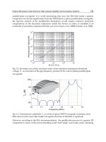
To check the orientation angle, the position in the XY frame coordinate of the top-end of
Colobot are measured for the six principal manipulator directions. Firstly, expected pres-
AdvancesinRobotManipulators14
sure combinations were used for Colobot to follow the six principal orientation angles
(0
◦
, 60
◦
, 120
◦
, 180
◦
, 240
◦
, 300
◦
) while the bending angle varied from 0
◦
to the maximum. Then
the measured positions of the top-end of Colobot were plotted relative to the original posi-
tion of Colobot without deformation. This experimental protocol leads to Fig. 15. This figure
highlights that the six orientation angles are in accordance with the theoretical values except
for high pressures in the chambers.
Fig. 15. Comparison of the orientation angle: measurement and simulation
4.3 Verification of the coupling between each chamber
Section 4.2 validated the bending angle and orientation angle separately in static. However,
most of the time the motion of the device results from the pressure differentials between each
chamber, this is to say, the interaction of each chamber. So it is necessary to check this mutual
interaction between each chamber. To achieve this goal, sinus reference signals of pressure
with 120
◦
delay are applied to each servovalve. They are employed to make Colobot turn
around its vertical axis with a constant velocity (see the experimental setup Fig. 13) to see the
mutual interaction of each chamber. By using miniBIRD, the endpoint coordinates of Colobot
can be obtained in XOY plane. Thus the comparison between these coordinates and those
obtained from the simulation of the kinematic model (Eq. 5) allows us to check if there are
interactions between chambers on the elongation of the prototype.
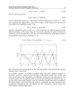
Two comparisons are then proposed in Figures 16 and 17. For the first case, three sinus signals
of pressure with amplitude of 0.4 bar and an offset of 0.9 bar are applied in the chambers of
the prototype. The path of the Colobot’s endpoint is a form of triangle (Fig. 16) because these
actuators of Colobot work across the threshold of their dead zones. For the latter case, three
sinus signals of pressure with amplitude of 0.4 bar and an offset of 1.2 bar are applied in the
chamber of Colobot. In this case, Colobot works in the working zone and the endpoint path
of Colobot lead to a circular shape (Fig. 17). The lines in the outer layer are the simulation
result from the kinematic model relating XY coordinates to the corresponding pressure of
each chamber (Eq. 4). Since the characteristics of deformation under pressure is performed
each chamber by each chamber independently (Eq. 4), the difference between the results
Fig. 16. Simulation et experimental results of the movement of the Colobot’s tip (across dead
zone)
of simulation and the experimental results showed in Figure 16 and Figure 17 suggests that
interactions exist among each chamber. These interactions are taken into account in section 4.4.
4.4 Estimation of a correction parameter
In this section, new parameters are chosen to represent the interactions between each cham-
ber. Thus, six stiffness parameters are introduced to describe the coupling effect of stretching
of one chamber to that of other two chambers. Let denotes k
ij
the mutual stiffness that deter-
mines the effect of P
i
(i=1,2,3) on the length of the chamber j (j = 1,2,3) (where i does not equal
j). The coefficients are obtained by minimizing the difference between the operational coor-
dinates (X
s
, Y
s
) measured by miniBIRD and the operational coordinates (X
m
, Y
m
) obtained by
simulation of the kinematic model (Fig. 18).
A classical non-linear optimization based on the Levenberg-Marquardt algorithm is pro-
ceeded to adjust the unknown parameters k
ij
. The cost criterion chosen is:
J
(k
ij
) =
(X
s
)
2
+ (Y
s
)
2
−
k
ij
(X
m
)
2
+ k
ij
(Y
m
)
2
)
(10)
The numerical results roughly lead tothe same coefficient k
= 0.3 for the unknown parameters
k
ij
. Thus the new expression of the kinematic model is given by:
∆L
1
= f
1
(P
1
) + 0.3( f
2
(P
2
) + f
3
(P
3
))
∆L
2
= f
2
(P
2
) + 0.3( f
1
(P
1
) + f
3
(P
3
))
∆L
3
= f
3
(P
3
) + 0.3( f
1
(P
1
) + f
2
(P
2
))
(11)
ABiomimeticsteeringrobotforMinimallyinvasivesurgeryapplication 15
sure combinations were used for Colobot to follow the six principal orientation angles
(0
◦
, 60
◦
, 120
◦
, 180
◦
, 240
◦
, 300
◦
) while the bending angle varied from 0
◦
to the maximum. Then
the measured positions of the top-end of Colobot were plotted relative to the original posi-
tion of Colobot without deformation. This experimental protocol leads to Fig. 15. This figure
highlights that the six orientation angles are in accordance with the theoretical values except
for high pressures in the chambers.
Fig. 15. Comparison of the orientation angle: measurement and simulation
4.3 Verification of the coupling between each chamber
Section 4.2 validated the bending angle and orientation angle separately in static. However,
most of the time the motion of the device results from the pressure differentials between each
chamber, this is to say, the interaction of each chamber. So it is necessary to check this mutual
interaction between each chamber. To achieve this goal, sinus reference signals of pressure
with 120
◦
delay are applied to each servovalve. They are employed to make Colobot turn
around its vertical axis with a constant velocity (see the experimental setup Fig. 13) to see the
mutual interaction of each chamber. By using miniBIRD, the endpoint coordinates of Colobot
can be obtained in XOY plane. Thus the comparison between these coordinates and those
obtained from the simulation of the kinematic model (Eq. 5) allows us to check if there are
interactions between chambers on the elongation of the prototype.
Two comparisons are then proposed in Figures 16 and 17. For the first case, three sinus signals
of pressure with amplitude of 0.4 bar and an offset of 0.9 bar are applied in the chambers of
the prototype. The path of the Colobot’s endpoint is a form of triangle (Fig. 16) because these
actuators of Colobot work across the threshold of their dead zones. For the latter case, three
sinus signals of pressure with amplitude of 0.4 bar and an offset of 1.2 bar are applied in the
chamber of Colobot. In this case, Colobot works in the working zone and the endpoint path
of Colobot lead to a circular shape (Fig. 17). The lines in the outer layer are the simulation
result from the kinematic model relating XY coordinates to the corresponding pressure of
each chamber (Eq. 4). Since the characteristics of deformation under pressure is performed
each chamber by each chamber independently (Eq. 4), the difference between the results
Fig. 16. Simulation et experimental results of the movement of the Colobot’s tip (across dead
zone)
of simulation and the experimental results showed in Figure 16 and Figure 17 suggests that
interactions exist among each chamber. These interactions are taken into account in section 4.4.
4.4 Estimation of a correction parameter
In this section, new parameters are chosen to represent the interactions between each cham-
ber. Thus, six stiffness parameters are introduced to describe the coupling effect of stretching
of one chamber to that of other two chambers. Let denotes k
ij
the mutual stiffness that deter-
mines the effect of P
i
(i=1,2,3) on the length of the chamber j (j = 1,2,3) (where i does not equal
j). The coefficients are obtained by minimizing the difference between the operational coor-
dinates (X
s
, Y
s
) measured by miniBIRD and the operational coordinates (X
m
, Y
m
) obtained by
simulation of the kinematic model (Fig. 18).
A classical non-linear optimization based on the Levenberg-Marquardt algorithm is pro-
ceeded to adjust the unknown parameters k
ij
. The cost criterion chosen is:
J
(k
ij
) =
(X
s
)
2
+ (Y
s
)
2
−
k
ij
(X
m
)
2
+ k
ij
(Y
m
)
2
)
(10)
The numerical results roughly lead tothe same coefficient k
= 0.3 for the unknown parameters
k
ij
. Thus the new expression of the kinematic model is given by:
∆L
1
= f
1
(P
1
) + 0.3( f
2
(P
2
) + f
3
(P
3
))
∆L
2
= f
2
(P
2
) + 0.3( f
1
(P
1
) + f
3
(P
3
))
∆L
3
= f
3
(P
3
) + 0.3( f
1
(P
1
) + f
2
(P
2
))
(11)