Advances in Solid State Part 5 doc
Bạn đang xem bản rút gọn của tài liệu. Xem và tải ngay bản đầy đủ của tài liệu tại đây (800.67 KB, 30 trang )
A Novel Multiclad Single Mode Optical Fibers for Broadband Optical Networks
111
type. Each of two types is divided to two other categories too named type I and II. A small
pulse broadening factor (small dispersion and dispersion slope), as well as small
nonlinearity (large effective area) and low bending loss (small mode field diameter) are
required as the design parameters in Zero dispersion shifted fibers [24]. The performance of
a design may be assessed in terms of the quality factor. This dimensionless factor
determines the trade-off between mode field diameter, which is an indicator of bending loss
and effective area, which provides a measure of signal distortion owing to nonlinearity [25].
It is also difficult to realize a dispersion shifted fiber while achieving small dispersion slope.
Here, we attempted to present an optimized MII triple-clad optical fiber to obtain exciting
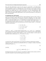
performance in terms of dispersion and its slope [24]. The index refraction profile of the MII
fiber structure is shown in Fig. 1. According to the LP approximation [26] to calculate the
electrical field distribution, there are two regions of operation and the guided modes and
propagating wave vectors can be obtained by using two determinants which are constructed
by boundary conditions [27].
Fig. 1. Refractive index Profile for MII Structure.
For calculation of dispersion and dispersion slope the following parameters are used.
,
b
P
c
=
(1)
,
a
Q
c
=
(2)
where P and Q are geometrical parameters. Also, the optical parameters for the structure are
defined as follows.
31
1
32
,
nn
R
nn
−
=
−
(3)
24
2
32
.
nn
R
nn
−
=
−
(4)
For evaluating of the index of refraction difference between core and cladding the following
definition is done.
22
34 34
2
44
2
nn nn
nn
−
−
Δ= ≈ (5)
Advances in Solid State Circuits Technologies
112
Here, we propose a novel methodology to make design procedure systematic. It is done by
the aim of optimization technique and based on the Genetic Algorithm. A
GA belongs to a
class of evolutionary computation techniques [28] based on models of biological evolution.
This method has been proved useful in the domains that are not understood well; search
spaces that are too large to be searched efficiently through standard methods. Here, we
concentrate on dispersion and dispersion slope simultaneously to achieve to the small
dispersion and its slope in the predefined wavelength duration. Our goal is to propose a
special fitness function that optimizes the pulse broadening factor. To achieve this, we have
defined a weighted fitness function. In fact, the weighting function is necessary to describe
the relative importance of each subset in the fitness function [24]; in other words, we let the
pulse broadening factor have different coefficient in each wavelength. To weight the
mentioned factor in the predefined wavelength interval, we have used the Gaussian
weighting function. The central wavelength (λ
0
) and the Gaussian parameter (σ) are used for
the manipulation of the proposed fitness function and their effects on system dispersion and
dispersion slope. To express the fiber optic structure, we considered three optical and
geometrical parameters. According to the GA technique, the problem will have six genes,
which explain those parameters. It should be mentioned that the initial range of parameters
are chosen after some conceptual examinations. The initial population has 50 chromosomes,
which cover the search space approximately. By using the initial population, the dispersion
(β
2
) and dispersion slope (β
3
), which are the important parameters in the proposed fitness
function, can be calculated. Consequently elites are selected to survive in the next
generation. Gradually the fitness function leads to the minimum point of the search zone
with an appropriate dispersion and slope. Equation (6) shows our proposal for the weighted
fitness function of the pulse broadening factor.
2
0
2
()
1
22
23
2
2
23
() ()
[1 ( ) ( ) ] ,
2
Z
ii
ZZ
Fe
tt
λλ
σ
λ
βλ βλ
−
−
=++
∑∑
(6)
where
02
,,,,
i
tZ
λ
σβ
and
3
β
are central wavelength, Gaussian parameter, full width at half
maximum, distance, second and third order derivatives of the wave vector respectively. In
the defined fitness function in Eq. (6), internal summation is proposed to include optimum
broadening factor for each length up to 200 km. By applying the fitness function and
running the GA, the fitness function is minimized. So, the small dispersion and its slope are
achieved. This condition corresponds to the maximum value for the dispersion length and
higher-order dispersion length as well. By using this proposal, the zero dispersion
wavelengths can be shifted to the central wavelength (λ
0
). Since, the weight of the pulse
broadening factor at λ
0
is greater than others in the weighted fitness function; it is more
likely to find the zero dispersion wavelength at λ
0
compared to the other wavelengths. In the
meantime, the flattening of the dispersion curve is controlled by Gaussian parameter (σ). To
put it other ways, the weighting Gaussian function becomes broader in the predefined
wavelength interval by increasing the Gaussian parameter (σ). As a result, the effect of the
pulse broadening factor with greater value is regarded in different wavelengths, which
causes a considerable decrease in the dispersion slope in the interval. Consequently, the zero
dispersion wavelength and dispersion slope can be tuned by λ
0
and σ respectively. The
advantage of this method is introducing two parameters (λ
0
and σ) instead of multi-
designing parameters (optical and geometrical), which makes system design easy.
A Novel Multiclad Single Mode Optical Fibers for Broadband Optical Networks
113
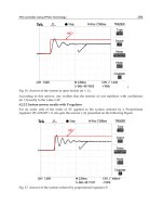
The flowchart given in Fig. 2 explains the foregoing design strategy clearly.
Fig. 2. The scheme of the design procedure
To illustrate capability of the suggested technique and weighted fitness function, the MII
triple-clad optical fiber is studied, and the simulated results are demonstrated below. In the
presented figures, we consider four simulation categories including dispersion related
quantities, nonlinear behavior of the proposed fibers, electrical field distribution in the
structures, and fiber losses.
For all the simulations, we consider λ0=1500, 1550 nm and σ = 0, 0.027869 and 0.036935 µm
as design constants. To apply the GA for optimization, we consider the search space
illustrated in Table 1 for each parameter as a gene. The choice of these intervals is done
according to two items. The designed structure must be practical in terms of manufacturing
and have high probability of supporting only one propagating mode [24].
Parameter
a (µm) p Q R
1
R
2
Δ
duration [2-2.6] [0.4-0.9] [0.1-0.7] [0.05-0.99] [(-0.99)- (-0.05)] [2×10
-3
- 1×10
-2
]
Table 1. Optimization Search Space of Optical and Geometrical Parameters
The wavelength and distance durations for optimization are selected as follows. For
λ
0
=1550nm: 1500 nm<λ< 1600 nm, for λ
0
=1500 nm: 1450 nm <λ< 1550 nm, and 0 < Z < 200
km. In this design method Z is variable. In the simulations an un-chirped initial pulse with 5
ps as full width at half maximum is used. Considering the information in Table 1 and GA
method, optimal parameters are extracted and demonstrated in Table 2.
Advances in Solid State Circuits Technologies
114
λ
0
(µm) a (µm) Δ R
1
R
2
p Q
1.55 2.0883 8.042e-3 0.5761 -0.4212 0.7116 0.3070
σ=0
1.5 2.1109 7.036e-3 0.6758 -0.2785 0.8356 0.2389
1.55 2.0592 9.899e-3 0.7320 -0.2670 0.7552 0.2599
8
2.7869 10
σ
−
=×
1.5 2.5822 9.111e-3 0.5457 -0.4237 0.7425 0.2880
1.55 2.2753 9.933e-3 0.5779 -0.4218 0.6666 0.3428
8
3.6935 10
σ
−
=×
1.5 2.5203 9.965e-3 0.4867 -0.3841 0.6819 0.3324
Table 2. Optimized Optical and Geometrical Parameters at λ
0
=1500, 1550 nm and three given
Gaussian parameters
It is found that optimization method for precise tuning of the zero dispersion wavelengths
as well as the small dispersion slope requires large value for the index of refraction
difference (Δ). That is to say that providing large index of refraction is excellent for the
simultaneous optimization of zero dispersion wavelength and dispersion slope. First, we
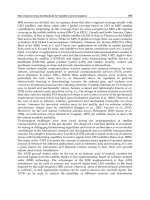
consider the dispersion behavior of the structures. To demonstrate the capability of the
proposed algorithm for the assumed data, the obtained dispersion characteristics of the
structures are illustrated in Fig. 3. It shows that the zero dispersion wavelengths can be
controlled precisely by controlling the central wavelength. Meanwhile, the Gaussian
parameters are used to manipulate the dispersion slope of the profile. Considering Fig. 3
and Table 3, it is found that the zero value for the Gaussian parameter can tune the zero
dispersion wavelengths accurately (~100 times better than other cases).
1.1 1.2 1.3 1.4 1.5 1.6 1.7 1.8 1.9
-40
-30
-20
-10
0
10
20
30
wavelength(um)
Dispersion(ps/km/nm)
σ
= 0
σ
= 2.7869e-8
σ
= 3.6935e-8
Fig. 3. Dispersion vs. Wavelength at λ0=1500nm, 1550nm with σ as parameter.
Second, the dispersion slope is examined. The presented curves say that by increasing the
Gaussian parameter the dispersion slope becomes smaller, and it is going to be smooth in
A Novel Multiclad Single Mode Optical Fibers for Broadband Optical Networks
115
large wavelengths. Furthermore it is clear that there is a trade-off between tuning the zero
dispersion wavelengths and decreasing the dispersion slope as shown in Figs. 3, 4, and
Table 3.
type
0
()m
λ
μ
Dispersion
(
)
//
p
skmnm
Dispersion
Slope
(
)
2
//
p
skmnm
Effective
Area
(
)
2
m
μ
Mode Field
Diameter
(
)
m
μ
Quality
Factor
1.55 -2.57e-4 0.0695 191.92 7.95 3.04
0
σ
=
1.5 2.55e-5 0.0828 344.15 9.76 3.61
1.55 -0.013 0.0647 194.79 7.12 3.85
8
2.7869 10
σ
−
=×
1.5 0.008 0.0597 209.95 6.70 4.68
1.55 -0.085 0.0592 150.05 6.82 3.22
8
3.6935 10
σ
−
=×
1.5 -0.089 0.0564 164.21 6.55 3.82
Table 3. Dispersion, Dispersion Slope, Effective Area, Mode Field Diameter and Quality
Factor at λ0=1500nm, 1550nm and three given Gaussian parameters
1.1 1.2 1.3 1.4 1.5 1.6 1.7 1.8 1.9
0.05
0.06
0.07
0.08
0.09
0.1
0.11
0.12
0.13
wavelength(um)
Dispersion Slope(ps/km/nm
2
)
1:
λ
= 1.5um
2:
λ
= 1.55um
0
0
σ
= 0
σ
= 2.7869e-8
σ
= 3.6935e-8
1
2
Fig. 4. Dispersion slope Vs. Wavelength at λ0=1500nm, 1550nm with σ as parameter.
The normalized field distribution of the MII based designed structures is illustrated in Figs.
5 and 6. Because of the special structure, the field distribution peak has fallen in region III.
As such most of the field distribution displaces to the cladding region. In addition it is
observed that the field distribution peak is shifted toward the core, and its tail is depressed
in the cladding region by increasing the Gaussian parameter (except σ=0). On the other hand
the field distribution slope increases inside the cladding region by increasing of the
Gaussian parameter.
Advances in Solid State Circuits Technologies
116
0 5 10 15 20 25 30
0
0.1
0.2
0.3
0.4
0.5
0.6
0.7
0.8
0.9
1
r(um)
Normalized Field Distribution
b:
σ
= 2.7869e-8
c:
σ
= 3.6935e-8
λ
=1.5 um
0
a
b
c
a:
σ
= 0
Fig. 5. Normalized Field distribution versus the radius of the fiber at λ
0
=1500nm with σ as
parameter (dashed-dotted, dotted, solid line, and dashed curves represent regions I, II, III
and IV respectively).
0 5 10 15 20 25 30
0
0.1
0.2
0.3
0.4
0.5
0.6
0.7
0.8
0.9
1
r(um )
Normalized Field Distribution
a:
σ
= 0
b:
σ
= 2.7869e-8
c:
σ
= 3.6935e-8
a
c
λ
=1.55 um
0
b
Fig. 6. Normalized Field distribution versus the radius of the fiber at λ
0
=1550nm with σ as
parameter (dashed-dotted, dotted, solid line, and dashed curves represent regions I, II, III
and IV respectively).
A Novel Multiclad Single Mode Optical Fibers for Broadband Optical Networks
117
The effective area or nonlinear behavior of the suggested structures is illustrated in Fig. 7. It
is observed that the effective area becomes smaller by increasing the Gaussian parameter.
Figs. 5–7, and Table 3 indicate a trade-off between the large effective area and the small
dispersion slope. The results illustrated in Fig. 4 show that the dispersion slope reduces by
increasing the Gaussian parameter. However the field distribution shifts toward the core,
which concludes the small effective area in this case. Foregoing points show that there is an
inherent trade-off between these two important quantities.
1.1 1.2 1.3 1.4 1.5 1.6 1.7 1.8 1.9
100
150
200
250
300
350
400
450
500
550
wavelength(um)
Effective Area(um
2
)
1:
λ
= 1.5um
2:
λ
= 1.55um
0
0
σ
= 0
σ
= 2.7869e-8
σ
= 3.6935e-8
1
2
Fig. 7. Effective area versus wavelength at λ
0
=1550nm, 1500nm with σ as the parameter.
The mode field diameter that corresponds to the bend loss is illustrated in Figs. 8 and 9 for
both central wavelengths. It is clearly observed that the mode field diameter decreases by
increasing the Gaussian parameter. In other words, the Gaussian parameter is suitable for
the bend loss manipulation in these structures. Furthermore, Table 3 shows that the mode
field diameter is ~7µm in the designed structure.
As another concept to consider, Table 3 says that the mode field diameter is not affected
noticeably by increasing the effective area. This is the origin of raising the quality factor in
these structures. This is a key point why the average amount of the quality factor in the
proposed structures is increased in Fig. 9. The quality factor of the designed fibers is
illustrated in Fig. 10. The calculations show that the quality factor is generally larger than 3.
It is mentionable that the quality factor is smaller than unity in the inner depressed clad
fibers (
W structures) and around unity in the depressed core fibers (R structures). This
feature shows the high quality of the putting forward methodology. It is observed that the
quality factor decreases by increasing the Gaussian parameter. It is strongly related to the
effective area reduction.
As another result the dispersion length is illustrated in Fig. 11 for the given Gaussian
parameter and two central wavelengths. The narrow peaks at λ=1500nm and 1550nm imply
Advances in Solid State Circuits Technologies
118
the precise tuning of the zero dispersion wavelengths. The higher-order dispersion length of
the designed fibers is demonstrated in Fig. 12. It is clear that the higher-order dispersion
length increases by raising the Gaussian parameter.
1.1 1.2 1.3 1.4 1.5 1.6 1.7 1.8 1.9
5
6
7
8
9
10
11
12
13
14
wavelength(um)
Mode Field Diameter(um)
λ
= 1.5um
0
σ
= 0
σ
= 2.7869e-8
σ
= 3.6935e-8
Fig. 8. Mode Field Diameter versus wavelength at λ
0
=1500nm with σ as parameter.
1.1 1.2 1.3 1.4 1.5 1.6 1.7 1.8 1.9
5
6
7
8
9
10
11
wavelength(um)
Mode Field Diameter(um)
λ
= 1.55um
0
σ
= 0
σ
= 2.7869e-8
σ
= 3.6935e-8
Fig. 9. Mode Field Diameter versus wavelength at λ
0
=1550nm with σ as parameter.
A Novel Multiclad Single Mode Optical Fibers for Broadband Optical Networks
119
1.1 1.2 1.3 1.4 1.5 1.6 1.7 1.8 1.9
2
2.5
3
3.5
4
4.5
5
5.5
6
wavelength(um)
Quality Factor
1:
λ
= 1.5um
2:
λ
= 1.55um
0
0
σ
= 0
σ
= 2.7869e-8
σ
= 3.6935e-8
1
2
Fig. 10. Quality Factor versus wavelength at λ
0
=1500nm, 1550nm with σ as parameter.
1.1 1.2 1.3 1.4 1.5 1.6 1.7 1.8 1.9
0
100
200
300
400
500
600
700
800
900
wavelength(um)
Dispersion Length(km)
σ
= 3.6935e-8
Fig. 11. Dispersion Length vs. Wavelength at
0
1.5, 1.55 .m
λ
μ
=
In the following, the nonlinear effect length for 1 mW input power is illustrated in Fig. 13.
First, it can be extracted that the suggested structures have the high nonlinear effect length.
For the general distances, these simulations show that the fiber input power can become
some hundred times greater to have the nonlinear effect length comparable with the fiber
Advances in Solid State Circuits Technologies
120
dispersion length. Second, the nonlinear effect length decreases and increases, respectively,
by raising the Gaussian parameter and wavelength.
1.1 1.2 1.3 1.4 1.5 1.6 1.7 1.8 1.9
500
1000
1500
2000
2500
3000
3500
4000
wavelength(um)
Higher Order Dispersion Length(km)
λ
= 1.55um
0
σ
= 0
σ
= 2.7869e-8
σ
= 3.6935e-8
Fig. 12. Higher Order Dispersion Length vs. Wavelength at
0
1.55 m
λ
μ
=
and Variance of the
weight function as parameter.
1.1 1.2 1.3 1.4 1.5 1.6 1.7 1.8 1.9
1.5
2
2.5
3
3.5
4
4.5
5
5.5
6
x 10
5
wavelength(um)
Nonlinear Effect Length(km)
λ
= 1.55um
0
σ
= 0
σ
= 2.7869e-8
σ
= 3.6935e-8
Fig. 13. Nonlinear Effective Length versus wavelength at λ
0
=1550nm with σ as parameter.
A Novel Multiclad Single Mode Optical Fibers for Broadband Optical Networks
121
The amount of the fiber bending loss strongly depends on the bend radius and the mode
field diameter. Figures 14 and 15, respectively, illustrate the bending loss (dB/m) versus the
bending radius (mm) at λ
0
= 1550 nm and 1500nm with variance of the weighting function
(σ) as a parameter. According to Figs. 8, 9, 14, and 15, it is clear that smaller mode field
diameter yields to the greater tolerance to the bending loss.
5 10 15 20 25 30 35
10
-7
10
-6
10
-5
10
-4
10
-3
10
-2
10
-1
10
0
Bending Loss(dB/m)
Bending radius(mm)
λ
= 1.55 um
0
σ
= 0.00
σ
= 2.7869e-8
σ
= 3.6935e-8
Fig. 14. Bending loss (dB/m) Vs. Bending radius at λ
0
=1550nm with
σ
as parameter.
0 10 20 30 40 50 60 70 80 90 100
10
-7
10
-6
10
-5
10
-4
10
-3
10
-2
10
-1
10
0
Bending radius(mm)
Bending Loss(dB/m)
λ
= 1.5 um
0
σ
= 0.00
σ
= 2.7869e-8
σ
= 3.6935e-8
Fig. 15. Bending loss (dB/m) Vs. Bending radius at λ
0
=1500nm with
σ
as parameter.
Advances in Solid State Circuits Technologies
122
All of the presented outcomes show that the suggested idea has capability to introduce a
fiber including higher performance. We have presented a novel method that includes the
small dispersion, its slope, high effective area, and small mode field diameter
simultaneously [24]. So all options required for the zero dispersion shifted communication
system are achieved successfully. This advantage is obtained owing to the selection of the
basic fiber structure as well as the method of optimization. Our selected fiber structure is the
MII, and we use the weighted fitness function applied in the GA for optimization. By
combining the suitable structure and the novel optimization method, all of the stated
advantages can be gathered simultaneously. The features of the proposed method are
capable of being extended to all of fiber structures, introduce two parameters instead of
multi-designing parameters, and tune the zero dispersion wavelengths precisely.
The ring index profiles fibers have been closely paid attentions because it has the larger
effective-areas that can minimize the harmful effects of fiber nonlinearity [29]. For the
proposed MII fiber structures, the small dispersion and its slope have been obtained thanks
to a design method based on genetic algorithm. But there is not any concentration on the
bending loss characteristic at the design process. Here we want to enter bending loss effect
on the fitness function directly and attempt to present an optimized RII triple-clad optical
fiber to obtain the wondering performance from dispersion, its slope, and bending loss
points of view. The index refraction profile of the RII fiber structure is shown in Fig. 16.
Fig. 16. Index of Refraction Profile for RII Structure
To calculate the dispersion, its slope and bending loss characteristics of the structure, the
geometrical and optical parameters are defined as follows.
b
P
c
=
,
a
Q
c
=
(7)
23
1
21
,
nn
R
nn
−
=
−
14
2
21
,
nn
R
nn
−
=
−
22
24 24
2
44
.
2
nn nn
nn
−−
Δ= ≈ (8)
The design method is based on the combination of the Genetic Algorithm (GA) and
Coordinate Descent (CD) approaches. It is well known that the GA is the scatter-shot and
the CD is the single-shot searching technique. The single-shot search is very quick compared
to the scatter-shot type, but depends critically on the guessed initial parameter values. This
description indicates that for the CD search, there is a considerable emphasis on the initial
search position. In this method, it is possible to define a fitness function and evaluate every
A Novel Multiclad Single Mode Optical Fibers for Broadband Optical Networks
123
individuals of the population with it. So we have combined the CD and GA methods to
improve the initial point selection with the help of generation elite and inherit the quick
convergence of coordinate descent [30]. In other words, we cover and evaluate the answer
zone by initial population and deriving few generations and use the elite of the latest
generation as an initial search position in the CD (Fig. 17).
Fig. 17. The Block Diagram of The Proposed Method
To derive the suggested design methodology, the following weighted cost function is
introduced. We have normalized the pulse broadening factor in the manner to be
comparable with bending loss. This normalization is essential to optimize the pulse
broadening factor and bending loss simultaneously. If not, the bending loss impact will be
imperceptible and be lost in the broadening factor term.
()
2
0
2
()
1
222
223
2
2
22 3
1()()()
[(1 ) ( ) ( ) ] ,
2
Z
ii i
ZZZ
Fe BL
zt t t
λλ
σ
λ
βλ βλ βλ
λ
−
−
⎛⎞
=++++
⎜⎟
⎝⎠
∑∑
(9)
The bending radius is set on 1 cm and kept still. The fitness function includes dispersion (β
2
),
dispersion slope (β
3
), and bending loss (BL) impacts. In the defined weighted fitness
function, internal summation is proposed to include optimum broadening factor for each
length up to 200 km. as said at the beginning of this section, one can adjust the zero
dispersion wavelength at λ
0
and dominate the dispersion slope by Gaussian parameter (σ).
The obtained dispersion behaviors of the structures are illustrated in Fig. 18 which
obviously demonstrates the λ
0
and σ parameters influences. It is clear that the zero-
dispersion wavelength is successfully set on λ
0
and the dispersion curve is become flatter in
the higher σ cases.
To show the capability of the proposed algorithm, Table 4 is presented to clarify the
different characteristics of these three structures. By considering on Fig. 18 and Table 4, it is
clear that there is a trade-off between the zero dispersion wavelength tuning and the
dispersion slope decreasing. In other words, it is found out that the zero value for the σ
parameter can tune the zero dispersion wavelength accurately ( ~100 times better than other
cases).
The effective area or nonlinear behavior of the suggested structures is listed in Table 4.
These values are high enough for the optical transmission applications. Owing to the special
structure of the RII type fiber, the field distribution peak has fallen in the first cladding
layer. As such most of the field distribution displaces to the cladding region. This is the
origin of large effective area in the designed structures. The normalized field distribution of
the RII based designed structures is illustrated in Fig. 19.
Advances in Solid State Circuits Technologies
124
1.3 1.35 1.4 1.45 1.5 1.55 1.6 1.65 1.7 1.75 1.8
-15
-10
-5
0
5
10
wavelength (um)
Dispersion (ps/km/nm)
σ
= 0.0
σ
= 1.12e-8
σ
= 3.69e-8
Fig. 18. Dispersion vs. Wavelength at λ
0
=1.55 µm.
type
D(λ=1.55 μm)
(ps/km/nm)
S(λ=1.55 μm)
(ps/km/nm
2
)
BL(λ=1.55 μm)
(dB/m)
A
eff
(λ=1.55 μm)
(μm
2
)
σ = 0.0 1.38e-4 0.048 1.90e-2 86.84
σ =1.12e-8 -6.15e-4 0.041 1.67e-1 82.53
σ =3.69e-8 4.50e-2 0.035 4.66e-2 86.01
Table 4. Dispersion, Dispersion Slope, Bending Loss, and Affective Area at λ
0
=1.55 μm and
Three Given Gaussian Parameters
Due to the refractive index thermo-optic coefficient and the thermal expansion coefficient,
the optical and geometrical parameters are altered. Consequently, the optical transmission
characteristics of the optical fiber such as dispersion, its slope and bending loss are
confronted to change. In order to evaluate the thermal stability of the designed structures,
the following results are extracted and presented in Table 5. The dD/dT, dS/dT, dλ
0
/dT, and
dBL/dT expressions are respectively the chromatic dispersion, its slope, zero dispersion
wavelength, and bending loss thermal coefficients at 1.55μm. It is found out that this
environmental factor must be considered in the desired optical fiber design. For example, in
the worst case, the zero dispersion wavelengths can be shifted more than 3 nm with 100°C.
In the least design we have focused on RII depressed core triple clad single mode optical
fiber and presented a combined optimization approach to obtain desirable design goals.
Furthermore, we have used the special fitness function including dispersion, its slope and
bending loss impacts simultaneously. With application of this fitness function in the case of
higher σ, we could obtain the dispersion and dispersion slope in [ 1.5 - 1.6 ] μm interval to be
A Novel Multiclad Single Mode Optical Fibers for Broadband Optical Networks
125
0 2 4 6 8 10 12 14
0
0.1
0.2
0.3
0.4
0.5
0.6
0.7
0.8
0.9
1
r (um)
Normalized Field Distribution
a
b
c
a:
σ
= 0.0
b:
σ
= 1.12e-8
c:
σ
= 3.69e-8
Fig. 19. Normalized field distribution versus the radius of the fiber at λ=1.55 μm with σ as
parameter (dashed, solid line, dotted, and dashed-dotted curve represent the core and three
cladding layers, respectively).
Type
dD/dT
(ps/km/nm/°C)
dS/dT
(ps/km/nm
2
/°C)
dλ
0
/dT
(nm/°C)
dBL/dT
(dBL/m/°C)
σ = 0.0 -1.22×10
-3
+2.83×10
-6
+2.5×10
-2
+3.97×10
-6
σ =1.12e-8 -1.21×10
-3
+2.93×10
-6
+3.33×10
-2
+2.70×10
-5
σ =3.69e-8 -1.21×10
-3
+2.93×10
-6
+2.5×10
-2
+8.79×10
-6
Table 5. Dispersion, Dispersion Slope, and Bending Loss Thermal Coefficients at λ
0
=1.55 μm
and Three Given Gaussian Parameters
[ ( -1.77 ) - ( +1.77 ) ] ps/km/nm and [ ( 0.037 ) – ( 0.033 ) ] ps/km/nm
2
. Also the amount of
bending loss at 1.55 μm with 1cm radius of curvature and effective area are 4.66e-2 dB/m
and 86.01 μm
2
respectively. In the meantime, the thermal stabilities of the designed
structures are evaluated. It is possible to design zero dispersion shifted by using graded
index structure. The main options are dispersion value and the effective area at 1550nm to
minimize pulse broadening and nonlinearity effects. Excess investigation of large mode area
fibers show that there is not serious focusing on design of zero dispersion shifted fiber based
on the graded index refractive structures. The index refraction profile of the triangular-core
graded index optical fiber structure, which is suggested by us for the first time, is shown in
Fig. 20. It is clear that the proposed graded index fiber has a linear variation in core region.
According to the TMM approach, it is assumed that the refractive index of the fiber with an
arbitrary but axially symmetric profile is approximately expressed by a staircase function.
So the field distribution and guided modes are calculated [26].
Advances in Solid State Circuits Technologies
126
Fig. 20. Refractive Index Profile for Triangular Core Graded Index Fiber Structure
Also for easy handling of the problem and calculating the dispersion and its slope of the
proposed fiber, following optical and geometrical parameters are defined.
22
14 14
2
44
,
2
nn nn
nn
−−
Δ= ≈
a
P
b
=
,
(
)
34 24
nn nn
η
=+ − ,
(
)
23 13
nn nn
μ
=+ − . (9)
In order to explain layers’ refractive index,
η
and μ coefficients are introduced and set
between 0 and 1. It must be declared that P parameter relates the cladding layer thickness
with the core radius. The design method is based on the limited coordinate descent (CD)
approach [30]. Based on the extensive investigation, it is found out that the smaller core
radius and larger refractive index difference lead the zero dispersion wavelength to around
1.55
μm. Therefore in order to design the dispersion shifted optical fiber, Δ and core radius
are set to 8
×10
-3
and 1.8μm respectively. Also it is assumed that the core and first cladding
layer have same thickness. Then direct search is done for
η
and
μ
parameters in the [0,1]
interval. To derive the suggested design methodology, the following fitness function is
introduced which includes the pulse broadening factor.
1
222
20 20 30
2
22 3
() () ()
[(1 ) ( ) ( ) ]
2
Z
ii i
ZZZ
F
tt t
βλ βλ βλ
=+ + +
∑
(10)
In the defined fitness function, the summation is proposed to include optimum broadening
factor for each length up to 200 km. The short glance on eq.(10) shows that the above fitness
function is a limited version of the past one [24], which the wavelength duration optimizing
is abbreviated. Also, it is not weighted because the fitness function is evaluated at single
wavelength (λ
0
). One can adjust the zero dispersion wavelength at λ
0
. It should be kept in
mind that in the fiber design, one likes to shift the zero dispersion wavelength to the region
that the fiber has the lowest level attenuation. The optical attenuation has a global minimum
around 1.55µm wavelength and that is why the most optical communication systems are
operated at this wavelength. Seeing that, the λ
0
parameter of the applied method is set to
1.55µm to achieve the desired zero dispersion shifted structure. Considering the parameter
presented above and CD method, the design procedure is driven and optimal parameters
are extracted and demonstrated in Table 6.
A Novel Multiclad Single Mode Optical Fibers for Broadband Optical Networks
127
Core radius Δ p η μ
*1.8μm 8×10
-3
0.5 0.25 0.44
*b=2a
Table 6. The Optical and Geometrical Parameters for the Designed Structure.
The value of the dispersion is –0.04549ps/km/nm at 1.55μm, which is properly small. The
nonlinear effects in a single mode fiber are the ultimate restricting factors for bit rate and
distance in long haul optical fiber communication system. Therefore, the large effective area
single mode fibers have been the subject of considerable studies recently. The effective area
of the suggested structure is 65.3
μm
2
at 1.55μm, which is acceptable for this application. The
associated mode field diameter at aforesaid wavelength is 9.03
μm.
8. Non-Zero Dispersion Shifted Fibers (NZDSFs)
Use of commercially available erbium doped fiber amplifiers (EDFA), which forces optical
communication systems to be operated in the 1550 nm window, has significantly reduced
the link length limitation imposed by attenuation in the optical fiber. However, high bit rate
(~ 10 Gb/s) data transmission can be limited by the large inherent dispersion of the fiber.
Dispersion shifted fibers (DSF), which has zero dispersion around 1550 nm, have been
proposed and developed to overcome this problem. However in order to increase the
information carrying capacity, latest high speed communication system is based on the
dense wavelength division multiplexing/demultiplexing (DWDM). In such systems,
nonlinear effects like four wave mixing (FWM), which arise due to simultaneous
transmission at many closely spaced wavelengths and high optical gain from EDFA,
imposes serious limitations on the use of a DSF with zero dispersion wavelength at 1550 nm.
To overcome this difficulty, the nonzero dispersion shifted fibers having small dispersion in
the range ~ 2−4 ps/km/nm over the entire gain window of EDFA have been proposed. In
such fibers, the phase matching condition is not satisfied and hence the effect of FWM
becomes negligible due to small dispersion. Nonlinear effects like cross phase modulation
(XPM), which limits the numbers of different wavelength signals, can be reduced by
increasing the mode field diameter (MFD) and hence effective area of the fiber. Therefore
large effective area nonzero dispersion shifted fibers have been developed [31]. To achieve
large effective area and low bending and splice loss with conventional fiber, a refractive
index profile, as shown in Fig. 21, is designed, which is mathematically described by Eq.
(11).
(11)
Advances in Solid State Circuits Technologies
128
where R
1
, R
2
, R
3
, R
4
are radius parameters, R
34
=(R
3
+R
4
)/2 is the center of the side core, n
1
, n
2
,
n
3
are the highest refractive index of central core, refractive index of cladding, and highest
refractive index of side core, respectively, Δ
1
=(n
1
-n
2
)/n
2
and Δ
2
=(n
3
-n
2
)/n
2
are the relative
profile heights of central core and side core, respectively, and α is the curve parameter. This
fiber consists of three parts, including a central core, side core and a cladding layer. The side
core inside the core region (i.e., the region r<R
4
) is designed to allow more signal energy to
flow into the cladding region so that a large effective area can be obtained [31].
Fig. 21. Refractive index profile of newly designed large effective area, low bending and
splice loss NZ-DSF.
From Eq. (11) it is found that the exact refractive index profile are controlled by seven
parameters (i.e., R
1
, R
2
, R
3
, R
4
, Δ
1
, Δ
2
, and α). To ensure the single mode operation, R4 must
be less than certain number. Thus, there are six parameters need to be optimized for
achieving the required dispersion slope, large effective area, low splice loss, low bending
loss, and low Rayleigh scattering loss simultaneously. By using the random searching
method, it is found that the fiber has the optimum performance under the following
conditions:
(12)
The Gaussian approximation method is used for calculating electrical field distribution for
the designed refractive index profile. The designed fiber has a dispersion about 4
ps/km/nm and dispersion slope about 0.06 ps/km/nm
2
at 1.55 µm operating wavelength,
which can be used to avoid four-wave mixing (FWM). Also the zero dispersion wavelength
is adjusted near 1480nm. In addition, calculation also shown that the designed fiber not only
has a large effective area over 100 µm
2
but also has low bending loss (<1.3×10
-3
dB with 30
mm bending radius and 100 turns) and low splice loss (<6.38×10
-3
dB) with conventional
A Novel Multiclad Single Mode Optical Fibers for Broadband Optical Networks
129
fiber. In order to broaden the wavelength range – not only the conventional C-band (1530–
1565 nm) – but also the L-band (1565–1620 nm) and S-band (1460–1530 nm), the dispersion
slope should be as low as possible, which can decrease the cost of dispersion compensation
and suppress the self-phase modulation, especially for the 40 Gb/s communication system.
Now we present a new depressed core index dual ring profile, which can provide a large
A
eff
and a low dispersion slope simultaneously, and the zero dispersion wavelength is less
than 1430 nm [32]. The fibers with this refractive index profile have the low bending loss
and low intrinsic loss. The splice loss also can reach the accepted value as it is spliced with
conventional single mode fiber. The principal design requirements for the fibers are large
A
eff
, small dispersion slope, low bending and intrinsic loss, low polarization-mode
dispersion, and zero dispersion wavelength that should be lower than 1430 nm.
Relative refractive index Δn
i
is defined by the equation: Δn
i
=(n
i
-n
c
)/n
c
, where n
c
is the outer
cladding layer’s refractive index. The dopant in the glass can decrease the glass viscosity, i.e,
more dopant concentration means less glass viscosity. High difference value between Δn
1
and Δn
2
may cause high difference value in viscosity property of the depressed core layer
and the first raised ring. Therefore, more mechanical stress will be built in the optical fibers
during the drawing process [33]. On the other hand, high difference value between layers’
refractive index can increase the compositional variation in the optical fiber. Therefore, more
thermal stress can be also caused by the radial variation of thermal expansion coefficient
due to the big compositional variation in optical fiber [34]. The residual stress in optical
fibers can not only weaken the strength of optical fibers, but also increase the fiber’s
attenuation and polarization mode dispersion values. According to the above description,
the refractive index profile shown in figure 22 is proposed to overcome problems. Every
parameters of the fiber profile are set out in Table 6, where Δn
i
are the relative refractive
index of different layer from the depressed core layer to the cladding, respectively.
Fig. 22. Improved refractive index profile with dual ring and depressed outer ring based on
the depressed core-index.
Δn
1
(%)
Δn
2
(%)
Δn
3
(%)
Δn
4
(%)
Δn
5
(%)
r
1
(µm)
r
2
(µm)
r
3
(µm)
r
4
(µm)
r
5
(µm)
0.14 0.57 -0.27 0.30 -0.18 2.50 4.10 6.88 9.98 12.41
Table 6. Parameters of refractive index profile shown in Fig. 22
Table 7 shows the optical characteristic of fabricated fiber designed according to the refractive
index profile parameters as Table 6, where MFD, RDS are the mode field diameter and relative
Advances in Solid State Circuits Technologies
130
dispersion slope, respectively. It is noted that the fiber has a large A
eff
of 105 µm
2
and a small
dispersion slope of about 0.065 ps/ km /nm
2
simultaneously. Macro bending loss at 1550 nm
is less than 0.05 dB/km (100 turns on the 60 mm diameter mandrel).
Parameters item
Wavelength
(nm)
Typical
value
1460 3.465
1550 9.569
Dispersion (ps/km/nm)
1625 14.324
Dispersion Slope(ps/km/nm
2
) 1550 0.0648
Zero dispersion wavelength (nm) - 1413
Attenuation (dB/km) 1550 0.210
MFD (µm) 1550 10.2
A
eff
(µm
2
) 1550 105.6
A
eff
×dispersion 1550 1010.5
RDS (nm
-1
) 1550 0.0068
PMD(ps/km
0.5
) 1550 0.04
1550 0.006 Macro bending loss for 100 turns on the 60mm
diameter (dB/km)
1625 0.015
Table 7. Optical characteristics of the fabricated fiber
From the table7 we can see that the zero dispersion wavelength is below 1430 nm, the
dispersion at 1460, 1550 and 1625 nm are 3.465, 9.569 and 12.324 ps/km/nm, respectively.
Therefore, this fiber not only can be used at the conventional C band for transmission link,
but also can be suited for S-band and L-band. With the progress being made in the practical
application of the Raman amplifier, this fiber also can be applicable in transmission links
using distributed Raman amplifier in the future. Furthermore, the value of A
eff
× dispersion
is also large enough to suppress the dispersion-related non-linear effects in the transmission
system [35]. It is obvious that a large effective area fiber with non-zero dispersion about 4
ps/km/nm at 1.55 µm wavelength band is a good approach to avoid four-wave mixing
(FWM) effect, which in turn enhances the performance of wavelength division multiplexing
(WDM) system [31]. However, such large effective area fibers have relatively large
dispersion slope which also restricts the numbers of different wavelength signals [21, 36-38].
Therefore, considerable efforts are being made to reduce the dispersion slope of such fibers
to deal with a rapid progress of DWDM system [39,40]. The refractive index profile of the
fiber is shown in Fig. 23. This profile has been named RI type in the literatures.
In order to obtain the flat modal field over the entire central dip region, the effective index (n
eff
)
of the mode should be equal to the refractive index of the central dip (i.e., n
eff
= n
1
) [15]. The
values of various parameters used in design of the dispersion characteristics are tabulated in
Table 8. Here, the relative index difference Δi is given by ∆i= (n
i
2
–n
4
2
)/2n
i
2
, i=1, 2, 3.
The values of the MFD and A
eff
associated with the modal field of the proposed design are
8.3 μm and 56.1 μm
2
, respectively. The total dispersion coefficient (D), which includes both
waveguide and material dispersion of the fiber, is calculated in the wavelength range of
1530 to 1610 nm, which covers the entire C- and L-bands of erbium doped fiber amplifiers.
In order to study the tolerance of the various characteristics of the proposed fiber design, we
have randomly changed the values of thickness and Δ of each region by 1%. The actual and
A Novel Multiclad Single Mode Optical Fibers for Broadband Optical Networks
131
the corresponding perturbed refractive index profiles are shown schematically in Fig. 23 by
the solid and dashed curves, respectively. Figure 24 shows the variation of the total
dispersion (D) with wavelength. The solid and dashed curves correspond to the actual and
the perturbed refractive index profiles, respectively. This figure indicates that over the entire
wavelength range of 1530 to 1610 nm, the dispersion value, which is within 2.6–3.4
ps/km/nm, for both profiles are within the appropriate range (2–4 ps/km/nm) needed to
avoid four wave mixing (FWM) [41].
Fig. 23. Schematic of the refractive index profiles of the proposed fiber (solid curve). The
dashed curve corresponds to the perturbed refractive index profile.
a(μm) b(μm) d(μm) ∆
1
(%) ∆
2
(%) ∆
3
(%)
1.0 3.1 6.5 0.03 0.48 -0.20
Table 8. The values of various parameters used in design
Fig. 24. Variation of the total dispersion (D) as a function wavelength. The solid and dashed
curves correspond to the proposed and the perturbed refractive index profiles (shown
schematically in Fig. 23), respectively.
Advances in Solid State Circuits Technologies
132
The dispersion and dispersion values of the designed fiber at λ
0
= 1550 nm is 3.0 ps/km/nm
and 0.01 ps/km/nm
2
, respectively. The maximum value of dispersion slope is 0.015 and 0.014
ps/km/nm
2
for the actual and perturbed refractive index profiles over the entire wavelength
range of 1530 to 1610 nm. This shows that the perturbation in the refractive index profile
does not make much change in the dispersion slope.
9. Dispersion Flattened Fibers (DFFs)
The dispersion value becomes larger by the wavelength increasing in the conventional
optical fibers. So owing to the dissimilar broadening for different channels, the multi-
channel application realization would be hard. A suitable optical fiber should meet the small
dispersion as well as the small dispersion slope in the predefined wavelength interval [42].
The concept of providing the attractive option of low dispersion over a range of
wavelengths was first suggested by Kawakami and Nishida in 1974 [43, 44]. They proposed
the original “W” fiber structure and explained the importance of a relatively narrow
depressed cladding region in modifying the waveguide dispersion to give a curve which
turned over to give two wavelengths for zero dispersion [45]. To minimize pulse broadening
in an optical fiber, the chromatic dispersion should be low over the wavelength range used.
A fiber in which the chromatic dispersion is low over a broad wavelength range is called a
dispersion-flattened fiber. The rms value, or the function f, to be minimized is:
(13)
where C is the chromatic dispersion. A normalized W profile is given by
(14)
where N
1
> 1 and N
2
< 1. The constraint that the first higher-order mode should appear
exactly at 1.25 μm is imposed. Thus there are four variables, namely, (N
1
, N
2
, b, a), and one
constraint. Assume that N
1
and N
2
are given certain fixed values. The values N
1
= 1.02 and
N
2
= 0.99 will prove to be interesting. If b = a, then the W profile has degenerated into a step-
index profile. The core radius, a, of this step-index fiber is easily calculated with the exact
cutoff condition V = 2.405, where V is the normalized frequency. The value N
1
= 1.02 yields b
= a = 1.64μm. Direct numerical calculation shows that if the outer radius, a, is increased then
the inner radius, b, must also be increased to keep the cutoff wavelength at 1.25 μm. Hence
the constraint λ
c
= 1.25 μm corresponds to a curved line in the a-b plane. The rms value of
the chromatic dispersion along this line is given in Fig. 25. The point of minimum dispersion
is easily located.
This procedure is repeated for different combinations of N
1
and N
2
, and the result is given in
Table 9. The first column of this table, i.e., N
2
= 1, corresponds to step-index profiles.
According to Table 9, the global minimum is 0.9 ps/km /nm, and the corresponding
optimal W fiber is (N
1
, N
2
, b, a) = (1.02, 0.99, 1.91, and 2.85 μm); see Fig. 26. It should be
observed that the global minimum is flat; i.e., there is a valley in Table 9 giving roughly the
same rms dispersion. Another observation is that the dependence of N
2
in Table 9 is weak if
N
1
is less than 1.01. On the other hand, the dependence of N
2
is strong if N
1
is greater than
1.01 and N
2
is close to unity.
A Novel Multiclad Single Mode Optical Fibers for Broadband Optical Networks
133
Fig. 25. The rms value of the chromatic dispersion over the vacuum wavelength range (1.25
μm, 1.60 μm) as a function of the outer radius a in a W fiber. The cutoff vacuum wavelength
is 1.25 μm. The relative refractive-index increases in the core and in the inner cladding are
1.02 and 0.99, respectively.
N
2
N
1
1.000 0.995 0.990 0.985 0.980
1.002 12 12 12 12 12
1.005 8.6 8.6 8.5 8.5 8.5
1.010 4.8 4.3 4.2 4.1 4.1
1.015 7.9 2.3 1.8 1.6 1.5
1.020 14 1.3 0.9 1.0 1.2
1.025 21 1.1 1.7 2.4 2.9
1.030 27 4.0 2.4 3.7 4.5
Table 9. Minimum rms chromatic dispersion (ps/km/nm) for different doping level in the
core & cladding
Fig. 26. Chromatic dispersion for the optimal W fiber (N
1
, N
2
, b, a) = (1.02, 0.99, 1.91 μm, 2.85
μm). The rms value of the chromatic dispersion over the vacuum wavelength range (1.25μm,
1.60 μm) is equal to 0.9 ps/km/ nm. The cutoff vacuum wavelength is 1.25 μm.
Advances in Solid State Circuits Technologies
134
An exhaustive method for calculating the minimum rms chromatic dispersion in W fibers
has been presented [45]. The procedure is to generate all W fibers with a certain cutoff
wavelength and then find the minimum rms dispersion by one-dimensional minimization
followed by direct inspection. It was found, in the case investigated, that the W fiber is
capable of dispersion flattening only if high doping levels are used. Dispersion and its slope
are responsible on the pulse broadening [4]. So we believe that mixing and gathering these
parameters on the design procedure would lead us to a fiber with exciting performances. In
other words, we concentrate on dispersion and slope simultaneously to achieve the small
dispersion and its slope in the predefined wavelength interval, the band which we want to
have flat dispersion behavior [42]. We use WII-type optical fiber structure which its
refractive index profile is shown in Fig. 27.
Fig. 27. The index of refraction profile for the proposed structures (WII)
Also, for easy handling of the problem the following optical parameters are defined as
follows.
13
1
32
,
nn
R
nn
−
=
−
24
2
32
,
nn
R
nn
−
=
−
22
14 14
2
44
.
2
nn nn
nn
−−
Δ= ≈
(15)
For this structure the geometrical parameters are introduced in the following.
b
P
c
=
,
a
Q
c
=
. (16)
To achieve the flattening purpose, we have defined a weighted fitness function. Equation
(17) shows our proposal for the weighted fitness function of the un-chirped pulse
broadening factor.
2
0
2
()
1
22
23
2
2
23
() ()
[1 ( ) ( ) ] ,
2
Z
ii
ZZ
Fe
tt
λλ
σ
λ
βλ βλ
−
−
=++
∑∑
(17)
It is useful to say that at first we applied this fitness function to design dispersion shifted
fiber. But outcomes presentation will show that this function is appropriate in Flattening
application too [42]. By using this fitness function, the zero dispersion wavelength can be
shifted to the central wavelength (λ
0
). Since, the weight of the pulse broadening factor at λ0
is greater than others in the weighted fitness function; it is more likely to find the zero
A Novel Multiclad Single Mode Optical Fibers for Broadband Optical Networks
135
dispersion wavelength at λ
0
compared to the other wavelengths. In the meantime, the
flattening of the dispersion curve is controlled by Gaussian parameter (σ). To put it in
another way, the weighting Gaussian function becomes broader in the predefined
wavelength interval by increasing the Gaussian parameter (σ). As a result, the effect of the
pulse broadening factor with greater value is regarded in different wavelengths, which
causes a considerable decrease in the dispersion slope in the interval. Consequently, the zero
dispersion wavelength and dispersion slope can be tuned by λ
0
and σ, respectively. The
wavelength and the distance durations for the design are defined as follows: 1.50 µm < λ <
1.60 µm; 0 < z < 200 km. In the simulations un-chirped initial pulse with 5 ps as full-width at
half-maximum is used. From Figure 28, it is clear that the zero dispersion wavelength is
successfully set at λ
0
which is equal to 1.55 µm. Furthermore, the dispersion curve becomes
so flat by adding the Gaussian weighting term to the fitness function. In other words, in the
absence of weighting function, the optimized dispersion has higher slope compared to its
presence.
1.3 1.4 1.5 1.6 1.7 1.8 1.9 2
-15
-10
-5
0
5
10
15
20
wavelengthg(um)
Dispersion(ps/km/nm)
σ
=1.2256e-8
σ
=0
Fig. 28. Dispersion versus Wavelength with and without weighting function
The impact of sigma parameter on the dispersion and its slope is illustrated in Figures 29
and 30. It is obvious that the dispersion value reduces by the sigma parameter increase in
the predefined wavelength interval and the curve is the smoothest in the highest sigma case.
This event can be described based on the fact that the weighting function (Gaussian
function) has large values around the central wavelength by the increase in the Gaussian
parameter. So, a large band of the wavelength around the central wavelength has almost the
same chance for optimization and thus the dispersion will be small and uniform for this
band. In other words, the duration of this band can be controlled by the sigma parameter.
The dispersion slope is strongly affected by the presence of σ in such a manner that its
increase has the considerable influence on the dispersion slope and decreases it obviously.
This result is easily visible in Figure 30 which shows the dispersion slope versus wavelength
with variance of the σ as a parameter. According to the presented weighted function based
GA optimization, the following optical and geometrical parameters are obtained. We find
out that the optimal value of R
2
for all Gaussian parameters are near to -1.