Báo cáo hóa học: " Electrical behavior of multi-walled carbon nanotube network embedded in amorphous silicon nitride" potx
Bạn đang xem bản rút gọn của tài liệu. Xem và tải ngay bản đầy đủ của tài liệu tại đây (1.27 MB, 6 trang )
NANO EXPRESS Open Access
Electrical behavior of multi-walled carbon
nanotube network embedded in amorphous
silicon nitride
Ionel Stavarache
1
, Ana-Maria Lepadatu
1
, Valentin Serban Teodorescu
1
, Magdalena Lidia Ciurea
1*
, Vladimir Iancu
2
,
Mircea Dragoman
3
, George Konstantinidis
4
, Raluca Buiculescu
5
Abstract
The electrical behavior of multi-walled carbon nanotube network embedded in amorphous silicon nitride is studied
by measuring the voltage and temperature dependences of the current. The microstructure of the network is
investigated by cross-sectional transmission electron microscopy. The multi-walled carbon nanotube net work has
an uniform spatial extension in the silicon nitride matrix. The current-voltage and resistance-temperature
characteristics are both linear, proving the metallic behavior of the network. The I-V curves present oscillations that
are further analyzed by computing the conductance-voltage characteristics. The conductance presents minima and
maxima that appear at the same voltage for both bias polarities, at both 20 and 298 K, and that are not periodic.
These oscillations are interpreted as due to percolation processes. The voltage percolation thresholds are identified
with the conductance minima.
Background
The carbon nanotubes (CNTs), either single-walled
(SWCNTs) or multi-walled (MWCNTs), have a quasi-
1D behavior that results from their nanometric dia-
meters and micrometric lengths [1-6]. While the
SWCNT structures correspond to t he rolling up of one
graphene sheet, the MWCNTs consist of several con-
centric sheets.
The electrical behavior of SWCNTs is determined by
their chirality, either metallic or semiconductor [7]. The
longitudinal conductance of a metallic one is quantified,
namely, G = nG
0
,withG
0
=2e
2
/h = 77.47 μSandn anat-
ural number. Th e behavior of MWCNTs is metallic if, at
least, one sheet has a metallic chirality. A theoretical analy-
sis on the conductance of infinitely long, defect-free
MWCNTs shows that the tunneling current between
states on different walls is vanishingly small [8], which
leads to the quantization of the conductance. In the frame
of this model, the authors showed that in a finite nano-
tube, the interwall conductance is negligible compared to
the intrawall ballist ic conductance. Ab rikosov et al. [9]
calculated the electron spectrum of a metallic MWCNT
with an arbitrary number of concentric sheets. They calcu-
lated the entropy and density of states for an MWCNT
and analyzed t he tunneling between the nanotube and a
metal ele ctrode . The auth ors proved t hat measuring the
tunneling conductivity at low temperatures, the one-elec-
tron d ensity of states can be directly determined. They
also give the necessary restrictions on temperature.
Kuroda and Leburton [10] modeled the linear beha-
vior of the R-T characteristics measured at low field in
SWCNTs, by ta king into account the mean free paths
determined by the interactions of electrons with acous-
tic and optical phonons. Their results are in good agree-
ment with the data from Refs [11,12]. This model is
generalized for MWCNTs in Ref. [13].
Li et al. [14] measured in individual vertical
MWCNTs with large diameters very large c urrents at
low bias voltage and they determined a very high con-
ductance, G =490G
0
, much higher than the value of
2G
0
, predicted in the literature for perfect metallic
SWCNTs.Theyexplainedthisbehaviorbyamulti-
channel quasiballistic transport of electrons in the
inner walls. In Ref. [ 15], Collins et al., studying the
limits of high energy transport in MWCNTs, showed
* Correspondence:
1
National Institute of Materials Physics, Magurele 077125, Romania.
Full list of author information is available at the end of the article
Stavarache et al. Nanoscale Research Letters 2011, 6:88
/>© 2011 Stavarache et al; licensee Springer. This is an Open Access article distributed under the terms of the Creative Commons
Attribution License (http://creati vecommons.org/licenses/by/2.0 ), which permits unrestricted use, distribution, and re production in
any medium, provided the orig inal work is properly cited.
that the nanotubes fail via a series of s harp and equal
current steps, in contrast to metal wires that fail con-
tinuously and in accelerating mode.
The percolation phenomena in films with MWCNTs
are extensively investigated in the literature, related to
film composition and thickness, temperature, nanotubes
concentration and shape, and so on. The electrical con-
ductivity o f oxidized MWCNT-epoxy composites was
investigated in Ref. [16]. The MWCNTs were oxidized
under both mild and strong conditions. Strong oxidation
conditions produce partially damaged nanotubes. Conse-
quently, their conducti vity dec reases and the percolatio n
threshold increases. On the contrary, the MWCNTs
oxidized under mild conditions present a high conductiv-
ity, independent of oxidation conditions. The study of
the conductivity as a function of film thickness and nano-
tube volume fraction [17] shows that reducing the film
thickness to a value comparable w ith the MWCNT
length, the percolation threshold significantly diminishes.
The authors explain this considering that different con-
ductive paths appear with different probabilities in a film
of MWCNT embedded in polyethylene.
The MWCNT -PMMA [poly(m ethyl methacrylate)]
composites also exhibit percolation phenomena. The dc
conductivity increases with increasing the MWCNTs con-
centration or mass [18-21], a typical percolation behavior.
A percolation threshold of 0.4 wt% was reported in Ref.
[20]. Using other polymers as a matrix, e.g., polydimethyl-
siloxane and styrene acrylic emulsion-based polymer,
percolation thresholds of 1.5 wt% [22] and 0.23 wt% were
found for MWCNTs [23]. The electrical behavi or of the
composite formed by an MWCNT network embedded in
PMMA is explained by a combination of Sheng’s fluctua-
tion induced tunneling and 1D variable range hopping
models [20 ]. Percolation in a 2D MWCNT network [24]
is strongly influenced by the MWCNT sizes and shape.
In the present letter we report on the electrical beha-
vior of an MWCNT network embedded in amorphous
silicon nitride matrix. The sample preparation and
microstructure investigations are presented. The voltage
and temperature dependences of the current were mea-
sured and the current-voltage, conductance-voltage, and
resistance-t emperature characteristics are discussed. The
observed conductance minima are interpreted as voltage
percolation thresholds, analogous to those pre viously
observed on nanostructures formed by nanocryst alline
silicon dots embedded in amorphous silicon dioxide
matrix, and also in nanocrystalline porous silicon [25].
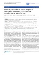
Experimental
The samples were prepared in a sandwich configuration
on a quartz substrate, as presented in Figure 1. The bot-
tom electrode is a 10 nm thin Cr layer as adhesion pro-
moter, and a 1 μm thick Al layer, deposited by “blanket”
electron gun evaporation. On this electrode, a solution
of MWCNTs (from Nanothinx S. A., Rio Patras,
Greece), with tetrahydrofuran (THF = (CH
2
)
4
O) with
the ratio MWCNT:THF = 0.22 mg/ml, was deposited by
pipetting. After, tetrahydrofuran evaporated, silicon
nitride was grown by PECVD to embed the MWCNTs.
A 3 minute reactive ion etching in CF
4
/O
2
mixture was
performed to etch the silicon nitride layer, until expos-
ing the top of the nano tubes layer. The final thickness
of silicon nitride with MWCNTs is about 8 μm. Then, a
30 minute reactive ion etching in CF
4
/O
2
mixture was
further performed to remove totally the silicon nitride
and the nano tub es at one end of the sample, for expos-
ing the bottom electrode. Finally, the top electrode of
10 nm Cr and 2 μm Al layers was deposited by electron
gun evaporation, to contact the protruding ends of the
nanotubes from the etched silicon nitride.
Cross-sectional transmission electro n microscopy
(XTEM) investigations were made on a Jeol TEM 200CX
instrument. The XTEM specimen was prepared by a con-
ventional method using mechanical polishing and ion
thinning in a Gatan PIPS device. Electrical measurements
were performed in a Janis CCS-450 cryostat at room
temperature (298 K ) and low temperature (20 K), using a
Keithley 6517A electrometer.
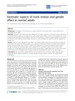
Results and discussions
A low magnification image of the cross-section spe ci-
men of the Cr/ Al/MWCNT-SiN/Cr/Al sandwich sample
is presented in Figure 2. It confirms the structure
expected from preparation, sketched in Figure 1. One
can obse rve that the MWCNT-SiN layer is about 8 μm
in thickness and has an amorphous and homogeneous
structure.
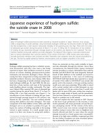
Figure 3 shows the microstructure of interfaces
between the electrodes and the MWCNT-SiN layer. The
bottom interface (Figure 3a) is neat. The Al crystallites
in the electrodes have a columnar morphology. The Cr
layer deposited on quartz is too thin to be seen in this
image. The top electrode interface looks d ifferent com-
pared with the bottom one (Figure 3b). At this interface,
Figure 1 Sample structure.
Stavarache et al. Nanoscale Research Letters 2011, 6:88
/>Page 2 of 6
the aluminum layer starts with small nanometric crystal-
lites, which are extended about 200 nm in the thickne ss
of the electrode. Then the struc ture becomes columnar
with big crystallites similar to those in the bottom elec-
trode. This difference is most probably induced by the
irregularities created by etching the top surface of the
MWCNT-SiN layer, and the presence of the few nm
thin Cr layer.
Looking at the XTEM specimen at higher magnifica-
tion it was possible to observe the presence of the
MWCNT in the SiN matrix. Figure 4 shows such a
nanotube(about30nmthick)nearthebottomelec-
trode. We have to mention the difficulty to observe the
MWCNTs embedded in amorphous SiN matrix by
XTEM, for two reasons. First one, it is a low difference
between the Z numbers of carbon, nitrogen, and silicon,
which forms the structure. However, the 10-20 nm thick
walls of the MWCNT show some low Bragg like con-
trast, coming from t he graphitic like lat tice planes, i n
the walls of the nanotube. This small contrast can be
observed only in the very thin areas of the XTEM speci-
men, similar to the case presen ted in Figure 4. The sec-
ond reason is the low density of the nanotubes network
in the MWCNT-SiN layer. Additional information about
the morphology of MWCNT network can be obtained if
the nanotubes are pipetted directly onto a carbon-
copper TEM grid, in a similar manner to that used for
the sample preparation. Figure 5 shows a detail of such
a spatial extension of MWCNT network formed on the
carbon layer on the TEM grid. Using the high angle tilt-
ing of the microscope goniometer, we can show that
such a netw ork is uniformly extended in space (3D
structure). Figure 5a,b shows the same area in the
MWCNT network deposited on the carbon TEM grid.
The image in Figure 5b is taken after the 30° tilting
of the area shown in the Figure 5a. Analyzing the differ-
ences between these two images, we can estimate the
depth of the network, which has the same order of mag-
nitude as its lateral size.
We can suppose that such a CNT network keeps the
same morphology during the deposition of the SiN
matrix. The final XTEM specimen consists only in a
sliceofabout50nmthickfromtheMWCNTnetwork
present in the SiN matrix. Consequently, in the XTEM
specimen,thepresenceofMWCNTswillberarely
observed, in the very thin part of the specimen. How-
ever, the repetitive observations of the same XTEM spe-
cimen after a series of sequential small duration of ion
milling allow us to observe different areas with
MWCNT network embedded in the SiN matrix.
Current -voltage characteristics are present ed in Figure
6. They have practically a linear dependence, at both
temperatures, typical for a metallic behavior. One can
observe that t he experimental points oscillate around
the linear fit li nes that give G ≈ 0.31 S for T = 298 K
and G ≈ 0.36 S for T =20K.
Figure 2 Low magnification image of a thick area of the XTEM
specimen.
Figure 3 XTEM images of the electrode/MWCNT-SiN interfaces. (a) bottom interface and (b) top interface.
Stavarache et al. Nanoscale Research Letters 2011, 6:88
/>Page 3 of 6
To analyze these oscillations, the conductance-voltage
curves were plotted (see Figure 7). These curves evi-
dence that the maxima and minima of the conductance
appear at the same voltages for both temperatures,
namely, 15 and 25 mV for the maxima and 20 and 30
mV for the minima on both polarities. In our opinion,
the conductance oscillations are due to percolation pro-
cesses and the minima represent voltage percolation
thresholds [25] . The percolation process in a disordered
MWCNTs network is due to the field-assisted tunneling
between neighboring nanotubes embedded in SiN. We
assume that SiN fills up all the space in the structure.
The interface between the nanotubes a nd the SiN
matrix does not show any porosity (see Figure 4). The
tunneling probability at the contact between MWCNTs
Figure 4 XTEM image of a 30 nm diameter carbon nanotube
embedded in the SiN matrix. The image is taken in an area near
the bottom electrode.
Figure 5 TEM images of the MWCNT network deposited on the
carbon TEM grid. The image (b) is taken after the 30° tilting of the
area shown in image (a).
Figure 6 I-V characteristics taken at 298 and 20 K.Inset:the
region of the voltage percolation thresholds (V > 0).
Figure 7 G-V characteristics taken at 298 and 20 K.
Stavarache et al. Nanoscale Research Letters 2011, 6:88
/>Page 4 of 6
varies as a function of their relative orientation and of
the applied field. As the conduction through a metallic
nanotube is quantified, it is expected that the current
cannot increase continuously with the voltage. There-
fore, the current-voltage curve tends to become sub-
linear [26] and the conductance reaches a minimum.
When the electric field overpasses a critical value (that
defines the voltage percolation threshold), the probabil-
ity of the tunneling between convenient neighboring
nanotubes increases enough to open less resistive paths.
Then the current-voltage curve becomes superlinear and
the conductance reaches a maximum. These minima
and maxima are not periodically depending on the vol-
tage and must be symmetric, meaning that they must
appear at the same absolute value of the voltage for
both bias polarities.
Conductance oscillations are previously presented in
articles where they are attributed to Coulomb blockade
effect [27,28], most of these results being observed in
SWCNTs. The oscillations found by Ahlskog et al. [28]
practically disappear when the sample temperature is
increased from 4.6 to 20 K. O n the other hand, the
oscillations observed by LeRoy et al. [27] measured at
4.5 K are periodically depending on the voltage.
The oscillations observed in our measurem ents do not
depend on the temperature and are not periodic. The
resistance-temperature characteristic taken at U =20
mV is presented in Figure 8. This characteristic is prac-
tically linear (except at low temperatures, under about
70 K). This is a supplementary argument for the metal-
lic behavior of our MWCNTs network.
Conclusions
The structure formed by the MWCNT network
embedded in SiN was XTEM investigated. The TEM
investigations, performed on nanotubes deposited
directly on the carbon grid, reveal a u niform spatial
extension of MWCNT network. In our opinion, this
structure is preserved when MWCNT network is
embedded in SiN.
The Cr/Al/MWCNT-SiN/Cr/Al samples present a
metallic behavior, which is proved by the linear charac-
ter of both the I-V and R-T characteristics.
The oscillations of the I- V and G-V curves are inter-
pret ed as due to percolatio n processes, as they are sym-
metric in bias polarization, are not periodic and are
temperature independent. The voltage percolation
thresholds of 20 and 30 mV on bot h bias polarities and
both temperatures (20 and 298 K) are given by th e con-
ductance minima.
Abbreviations
CNTs: carbon nanotubes; MWCNTs: multi-walled carbon nanotubes; PMMA:
poly(methyl methacrylate); SWCNTs: single-walled carbon nanotubes; THF:
tetrahydrofuran; XTEM: cross-sectional transmission electron microscopy.
Acknowledgements
The Romanian contribution to this work was supported by the Romanian
National Authority for Scientific Research through the CNMP Contract
10-009/2007, the Ideas Program Contract 471/2009 (ID 918/2008), and the
Core Program Contract PN09-45.
Author details
1
National Institute of Materials Physics, Magurele 077125, Romania.
2
“Politehnica” University of Bucharest, Bucharest 060042, Romania.
3
National
Institute for Research and Development in Microtechnologies, Bucharest
023573, Romania.
4
Institute of Electronic Structures and Laser, Foundation for
Research and Technology-Hellas, Heraklion 70013, Crete, Greece.
5
University
of Crete, Voutes Campus, Heraklion 71003, Crete, Greece.
Authors’ contributions
IS and AML carried out all electrical measurements and participated to
modeling. VST carried out XTEM investigations. MLC conceived and
coordinated the study, participated to modeling and drafted the manuscript.
VI participated to modeling and writing the manuscript. MD carried out the
design of the device. GK carried out the device fabrication. RB carried out
the MWCNT deposition. All authors read and approved the final manuscript.
Competing interests
The authors declare that they have no competing interests.
Received: 2 August 2010 Accepted: 17 January 2011
Published: 17 January 2011
References
1. Simmons TJ, Hashim D, Vajtai R, Ajayan PM: Large area-aligned arrays
from direct deposition of single-wall carbon nanotube inks. J Am Chem
Soc 2007, 129:10088-10089.
2. Avouris P, Chen ZH, Perebeinos V: Carbon-based electronics. Nat
Nanotechnol 2007, 2:605-615.
3. Leonard F: The Physics of Carbon Nanotube Devices Norwich: William
Andrew; 2009.
4. Javey A, Kong J, (Eds): Carbon Nanotube Electronics New York: Springer;
2009.
5. Dragoman M, Dragoman D: Nanoelectronics, Principles and Devices Boston:
Artech House; 2009.
6. Green AA, Hersam MC: Processing and properties of highly enriched
double-wall carbon nanotubes. Nat Nanotechnol 2009, 4:64-70.
7. Dekker C: Carbon nanotubes as molecular quantum wires. Phys Today
1999, 52:22-28.
Figure 8 R-T characteristic taken at U =20mV.
Stavarache et al. Nanoscale Research Letters 2011, 6:88
/>Page 5 of 6
8. Yoon YG, Delaney P, Louie SG: Quantum conductance of multiwall carbon
nanotubes. Phys Rev B 2002, 66:073407, (1-4).
9. Abrikosov AA Jr, Livanov DV, Varlamov AA: Electronic spectrum and
tunneling properties of multiwall carbon nanotubes. Phys Rev B 2005,
71:165423, (1-8).
10. Kuroda MA, Leburton JP: High-field electrothermal transport in metallic
carbon nanotubes. Phys Rev B 2009, 80:165417, (1-10).
11. Park JY, Rosenblatt S, Yaish Y, Sazonova V, Ustunel H, Braig S, Arias T,
Brouwer P, McEuen P: Electron-phonon scattering in metallic single-
walled carbon nanotubes. Nano Lett 2004, 4:517-520.
12. Javey A, Guo J, Paulsson M, Wang Q, Mann D, Lundstrom M, Dai H: High-
field quasiballistic transport in short carbon nanotubes. Phys Rev Lett
2004, 92:106804, (1-4).
13. Fujita S, Suzuki A: Theory of temperature dependence of the conductivity
in carbon nanotubes. J Appl Phys 2010, 107:013711, (1-4).
14. Li HJ, Lu WG, Li JJ, Bai XD, Gu CZ: Multichannel ballistic transport in
multiwall carbon nanotubes. Phys Rev Lett 2005, 95:086601, (1-4).
15. Collins PG, Hersam M, Arnold M, Martel R, Avouris P: Current saturation
and electrical breakdown in multiwalled carbon nanotubes. Phys Rev Lett
2001, 86:3128-3131.
16. Kim YJ, Shin TS, Choi HD, Kwon JH, Chung YC, Yoon HG: Electrical
conductivity of chemically modified multiwalled carbon nanotube/epoxy
composites. Carbon 2005, 43:23-30.
17. Fu M, Yu Y, Xie JJ, Wang LP, Fan MY, Jiang SL, Zeng YK: Significant
influence of film thickness on the percolation threshold of multiwall
carbon nanotube/low density polyethylene composite films. Appl Phys
Lett 2009, 94:012904, (1-3).
18. Kim HM, Kim K, Lee CY, Joo J, Cho SJ, Yoon HS, Pejaković DA, Yoo JW,
Epstein AJ: Electrical conductivity and electromagnetic interference
shielding of multiwalled carbon nanotube composites containing Fe
catalyst. Appl Phys Lett 2004, 84:589-591.
19. Kim HM, Kim K, Lee SJ, Joo J, Yoon HS, Cho SJ, Lyu SC, Lee CJ: Charge
transport properties of composites of multiwalled carbon nanotube with
metal catalyst and polymer: application to electromagnetic interference
shielding. Curr Appl Phys 2004, 4:577-580.
20. Kim HM, Choi MS, Joo J, Cho SJ, Yoon HS: Complexity in charge transport
for multiwalled carbon nanotube and poly(methyl methacrylate)
composites. Phys Rev B 2006, 74:054202, (1-7).
21. Curran SA, Talla J, Dias S, Zhang D, Carroll D, Birx D: Electrical transport
measurements of highly conductive carbon nanotube/poly (bisphenol A
carbonate) composite. J Appl Phys 2009, 105:073711, (1-5).
22. Khosla A, Gray BL: Preparation, characterization and micromolding of
multi-walled carbon nanotube polydimethylsiloxane conducting
nanocomposite polymer. Mater Lett 2009, 63:1203-1206.
23. Li Y, Chen C, Li JT, Zhang S, Ni Y, Cai S, Huang J: Enhanced dielectric
constant for efficient electromagnetic shielding based on carbon-
nanotube-added styrene acrylic emulsion based composite. Nanoscale
Res Lett 2010, 5:1170-1176.
24. Lee HS, Yun CH, Kim SK, Choi JH, Lee CJ, Jin HJ, Lee H, Park SJ, Park M:
Percolation of two-dimensional multiwall carbon nanotube networks.
Appl Phys Lett 2009, 95:134104, (1-3).
25. Stavarache I, Ciurea ML: Percolation phenomena in Si-SiO
2
nanocomposite films. J Optoelectron Adv Mater 2007, 9:2644-2647.
26. Shimizu T, Abe H, Ando A, Nakayama Y, Tokumoto H: Electrical
conductivity measurements of a multi-walled carbon nanotube. Surf
Interface Anal 2005, 37:204-207.
27. LeRoy BJ, Heller I, Pahilwani VK, Dekker C, Lemay SG: Simultaneous
electrical transport and scanning tunneling spectroscopy of carbon
nanotubes. Nano Lett 2007, 7:2937-2941.
28. Ahlskog M, Herranen O, Johansson A, Leppäiniemi J, Mitsuko D: Electronic
transport in intermediate sized carbon nanotubes. Phys Rev B 2009,
79:155408, (1-5).
doi:10.1186/1556-276X-6-88
Cite this article as: Stavarache et al.: Electrical behavior of multi-walled
carbon nanotube network embedded in amorphous silico n nitride.
Nanoscale Research Letters 2011 6:88.
Submit your manuscript to a
journal and benefi t from:
7 Convenient online submission
7 Rigorous peer review
7 Immediate publication on acceptance
7 Open access: articles freely available online
7 High visibility within the fi eld
7 Retaining the copyright to your article
Submit your next manuscript at 7 springeropen.com
Stavarache et al. Nanoscale Research Letters 2011, 6:88
/>Page 6 of 6