Báo cáo hóa học: " Research Article An Analytical Modeling of Polarized Time-Variant On-Body Propagation Channels with Dynamic Body Scattering" doc
Bạn đang xem bản rút gọn của tài liệu. Xem và tải ngay bản đầy đủ của tài liệu tại đây (4.16 MB, 12 trang )
Hindawi Publishing Corporation
EURASIP Journal on Wireless Communications and Networking
Volume 2011, Article ID 362521, 12 pages
doi:10.1155/2011/362521
Research Ar ticle
An Analytical Modeling of Polarized Time-Vari ant On-Body
Propagation Channels with Dynamic Body Scattering
Lingfeng Liu,
1, 2
Farshad Keshmiri,
1
Christophe Craeye,
1
Philippe De Doncker,
2
and Claude Oestges
1
1
ICTEAM Electrical Engineering, Universit´e Catholique de Louvain, 3 Place du Levant, 1348 Louvain-la-Neuve, Belgium
2
OPERA Department, Universit´e Libre de Bruxelles, CP 194/5, Avenue F. D. Roosevelt 50, 1050 Bruxelles, Belgium
Correspondence should be addressed to Lingfeng Liu,
Received 5 October 2010; Accepted 13 January 2011
Academic Editor: Dries Neirynck
Copyright © 2011 Lingfeng Liu et al. This is an open access article distributed under the Creative Commons Attribution License,
which permits unrestricted use, distribution, and reproduction in any medium, provided the original work is properly cited.
On-body propagation is one of the dominant propagation mechanisms in wireless body area networks (WBANs). It is
characterized by near-field body-coupling and strong body-scattering effects. The temporal and spatial properties of on-body
channels are jointly affected by the antenna polarization, the body posture, and the body motion. Analysis on the time variant
properties of on-body channels relies on a good understanding of the dynamic body scattering, which is highly dependent on
specific scenarios. In this paper, we develop an analytical model to provide a canonical description of on-body channels in both
time and space domains to investigate the on-body propagation over the trunk surface of a walking human. The scattering from
the arms and the trunk in different dimensions is considered with a simplified geometrical description of the body and of the body
movements during the walk. A general full-wave solution of a polarized point source with multiple cylinder scattering is derived
and extended by considering time evolution. The model is finally validated by deterministic and statistical comparisons to different
measurements in anechoic environments.
1. Introduction
Wireless body area networks (WBANs) are innovative short-
range wireless networks enabling communication between
compact devices, which are placed inside, on, or around the
human body. The promising capability of WBANs to convey
biomedical information and personal data has attracted a
vast range of wireless body-centric applications in recent
years [1].
Wireless medical applications, such as wireless monitor-
ing and remote healthcare, are important applications of
WBANs. These applications have strict requirements on the
power consumption and communication reliability, which
have to be supported by low-power, long-term communi-
cation technologies like ZigBee [2, 3]. In these technologies,
biomedical signals, for example, electrocardiography (ECG)
or blood pressure, are detected and transmitted from
spatially distributed sensors to a body-worn data collector for
processing and transmitting to the outside world. Such trans-
mission relies on the signal waves propagating on the surface
of the human body, that is, on-body propagation. Unlike
conventional large-scale propagation (indoors, outdoors,
etc.), on-body propagation usually occurs in the near-field
and undergoes strong body-coupling and body-scattering
effects. Although realistic on-body channels are also affected
by scattering from the objects surrounding the body, the
particularity of on-body scattering is that it is always present,
and that its characteristics are largely independent of the
off-body environment. Moreover, on-body scattering also
significantly modifies antenna radiation patterns, further
affecting the level of off-body versus on-body contributions
[4, 5]. For these reasons, a separate study of on-body
scattering is fundamental to understand WBAN propagation
in both theoretical analysis and practical applications.
Body-scattering results from the joint scattering from
different body components (trunk, arms, legs, etc.). Due to
the finite size and complex shape of the body, the impact
of body scattering significantly differ depending on the
antenna locations on the body. This will lead to different
on-body path loss in different regions and dimensions on
2 EURASIP Journal on Wireless Communications and Networking
the body. In the time domain, certain body motions also
cause body scattering to become dynamic, which results in
time-variant on-body channel fading. However, given the
large variety of antenna positions and body motions, an
effective characterization of the on-body channels should
be scenario specific with well-defined spatial distributions
of on-body channels and patterns of the body move-
ments.
The importance of the polarization has also been
addressed by most WBAN studies [6]. Yet, the investigations
are not sufficient because of measurement limitations and
analyzing difficulties. The polarization is another sensitive
parameter that affects both the on-body path loss and
fading. There are two basic types of polarizations: tangential
and normal to the body surface. Propagations in different
polarizations along different dimensions on the body are
usually distinct. In practical applications, polarization of
the antennas can easily be modified by the posture and
movement of the body, which will introduce significant
disturbance on the link quality and the performance of the
on-body communications, as demonstrated in [6]. A specific
and analytical investigation on the polarization is thereby
necessary to better understand the mechanism of on-body
propagation and to properly design on-body communication
systems.
Studies on WBAN propagation resort to various ap-
proaches. Empirical investigations have been widely adopted
as in [7–10]. This approach reflects the reality but is
insufficient to get an insight on the physical mechanisms
involved in on-body scattering. Complex Finite-Difference
Time-Domain (FDTD) simulations as in [11, 12]isanother
popular method to describe on-body propagation with a
high resolution, but it is also quite time consuming if the
dynamic body scattering is simulated. Analytical modeling,
as studied in [13–15] with simplified geometric descriptions
of the human body, is a compromise between precision
and efficiency to describe the essential properties of on-
body channels in different domains. Analytical models are
also able to provide canonical channel characterizations
with sufficient details, for example, on the spatial corre-
lation to exploit the channel spatial diversity for commu-
nication enhancing techniques like cooperative multilink
[16].
In this work, we develop an analytical model with respect
to a typical on-body propagation scenario on a walking
human being. The investigated on-body transmissions are
located on the trunk surface, where the scattering from
the trunk and the arms are considered. Cylindrical shapes
are introduced to describe the trunk and arms, while the
body motion is modeled by simplified arm traces in the
azimuth plane. An arbitrarily polarized point source is
considered in the model and the general full-wave solution
of the source with multiple cylinder scattering is derived
and extended to include time evolution. The model is finally
validated through deterministic and statistical comparisons
with different on-body propagation measurements in ane-
choic environment.
The paper is organized as follows. Sections 2 and 3,
respectively, describe the investigated on-body propagation
scenario and the modeling approach. In Section 4,the
field solution is derived, with its extension to time evo-
lution. The experimental model validation is presented in
Section 5, and conclusions of the current work are drawn in
Section 6.
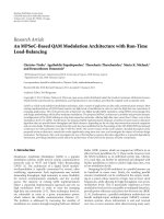
2. Scenario Description
We consider a specific scenario of a walking human with a
natural posture as depicted in Figure 1(a).Thetypicalbody
movements during the walk are composed of two parts, the
footwork and the arm swing. Both of them are rhythmic
and quasiperiodic processes. In this scenario, the transmitter
(Tx) and the receiver (Rx) of an on-body channel are both
located on the trunk surface, as marked in Figure 1(b).It
is assumed that on-body transmissions on the trunk are less
affected by the scattering from the legs, so that the dominant
scattering effects are from trunk and arms. Both Tx and Rx
are assumed to be small-sized sensors that are fixed on the
trunk surface with invariant positions and constant distance
to the skin.
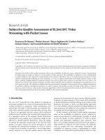
3. Body and Current Source Mo deling
In the described scenario, we use three infinite, homoge-
neous, and lossy cylinders to model the trunk and the arms
as in Figure 2(a). Although the elliptic cylinder is closer to the
actual shape of the trunk as studied in [15], the complexity
to analytically solve the scattering from the elliptic cylinder
will be dramatically high, yet the improvement brought to
the model is limited. The cylinders are then vertically placed
and are allowed to have parallel movements in the azimuth
plane. The conductivity of the cylinders is determined by the
cole-cole model [17],andthecylindersareassumedtobe
composed by dry skin. The permeability, permittivity, and
wavenumber in free space and in the cylinders are denoted
by (μ
0
,
0
, k
0
)and(μ, , k), respectively.
The Tx antenna is modeled by a polarized point source
with constant electric current intensity, I. The polarization of
the source is described by a direction vector, as in Figure 2(b).
In view of the regular geometry of the body, the source is
fixed at height z
= 0.
The sizes and positions of the cylinders and of the
source in the azimuth plane are described in the global
polar coordinate in Figure 2(c). For simplicity, the cylinder
representing the trunk is located at the global origin. The
scenario can be generalized as a number of P cylinders being
vertically placed with a polarized point source located in the
azimuth plane z
= 0. The radii of different cylinders are
denoted as r
p
, p being the index of the cylinder. We attributed
a local coordinate (φ
p
, ρ
p
) to each cylinder that the center
of the cylinder is located at its local origin, denoted as O
p
.
The position of the source in azimuth is denoted as (φ
s
, ρ
s
)
in the global coordinate system, and (φ
ps
, ρ
ps
) in each local
coordinate system.
EURASIP Journal on Wireless Communications and Networking 3
(a) Walking scenario with normal posture and
movements
Tx
Rx
(b) Distribution of Tx and Rx. Both of them are
located on the trunk surface
Figure 1: The investigated on-body propagation scenario on a walking human.
4. Field Solution
4.1. General Structu re. The scattering problem in the model
contains two parts: the representation of point source field
and the full-wave solution of multiple cylinder scattering.
In [13], an integration method was introduced to
represent a point current source by Fourier series of line
current source, as expressed by
J
=
I
2πρ
s
δ
ρ −ρ
s
+∞
m=−∞
e
jm(φ−φ
s
)
e
−jk
z
z
vdk
z
,(1)
where k
z
=
k
2
−k
2
ρ
is the wavenumber along the z
direction, k
ρ
is the wavenumber along the ρ direction, and
v is the direction vector of the source polarization. The sum
of complex exponentials in (1) denotes the decomposition of
thelinesourceintocylindricalcurrentsheets.
By (1), the point source scattering is equivalently
expressed by the integration of line source scattering with
different values of k
z
,as
E
point
ρ, φ, z
=
1
2π
+∞
−∞
E
line
ρ, φ, k
ρ
e
−jk
z
z
dk
z
,
H
point
ρ, φ, z
=
1
2π
+∞
−∞
H
line
ρ, φ, k
ρ
e
−jk
z
z
dk
z
.
(2)
The contour of poles through proper integration path is
also well described in [13].
The multiple cylinder scattering has been investigated
by earlier studies as in [18, 19]forplanewavepropagation.
This paper will focus on the full-wave solution of a polarized
line source with multiple-cylinder scattering. Convention-
ally, the total field is composed by the incident field from the
line source and the scattered fields from the cylinders.
In (1), the line source inherits the polarization of the
point source. The source current is then decomposed into
polarization components along z, φ,andρ directions, as in
Figure 2(b). The current intensity of each polarization com-
ponent fulfills I
=
|I
ρ
|
2
+ |I
φ
|
2
+ |I
z
|
2
.Thetotalincident
field is then the summation of the incident field from each
polarization component. With the principles in [13, 20], the
incident fields from each polarization component along z,
φ,andρ directions can be expressed, respectively, as the
summation of cylindrical harmonics over different orders m,
as
E
i
m,α
= E
iz
m,α
+ E
iφ
m,α
+ E
iρ
m,α
,
H
i
m,α
= H
iz
m,α
+ H
iφ
m,α
+ H
iρ
m,α
,
(3)
where, for example, E
iz
m,α
and H
iz
m,α
, α = z/φ/ρ,denotethe
incident E and H fields from the z-polarization component
along the α direction at order m.Equation(3)providesthe
complete incident field expression for arbitrary polarized
current source along different dimensions.
In [13], the explicit numerical expression of the incident
fields from polarization components I
z
and I
φ
were given. In
this work, the numerical expression of the incident field from
polarization component I
ρ
is derived in Section 4.2.
4 EURASIP Journal on Wireless Communications and Networking
Z
X
Y
(a) The body and current source modeling
Z
X
Y
0
I
z
I
φ
I
ρ
I
(b) The source polarization description
90
◦
180
◦
0
◦
270
◦
Back
Front
r
arm
r
arm
Left
d
ab
d
ab
r
body
φ
s
Right
d
s
I
e
d
l0
(c) Geometric quantization of the body and the source
in azimuth plane. r
body
is the trunk radius, r
arm
is the
arm radius, d
ab
is the distance between the arm and the
trunk, and d
s
is the distance from the source to the trunk
surface. The d
l0
= (r
body
+d
s
)φ
s
is the corresponding surface
distance from the source to the trunk central
Figure 2: The human body and transmitter modeling by three lossy cylinders and one polarized point source.
The total scattered fields can be viewed as the summation
of the individual scattered field from each cylinder. By
[13], the individual scattered field can be expressed as the
summation of cylindric harmonics in its local coordinate
system. Normally, at order m,thescatteredfieldfrom
cylinder p along z direction can be expressed in its local
coordinate as:
E
s,p
m,z
ρ
p
, φ
p
=
⎧
⎪
⎨
⎪
⎩
A
p
m
J
m
k
ρ
ρ
p
e
jm(φ
p
−φ
ps
)
, ρ
p
≤ r
p
,
B
p
m
H
(2)
m
k
ρ0
ρ
p
e
jm(φ
p
−φ
ps
)
, ρ
p
>r
p
,
H
s,p
m,z
ρ
p
, φ
p
=
⎧
⎪
⎨
⎪
⎩
C
p
m
J
m
k
ρ
ρ
p
e
jm(φ
p
−φ
ps
)
, ρ
p
≤ r
p
,
D
p
m
H
(2)
m
k
ρ0
ρ
p
e
jm(φ
p
−φ
ps
)
, ρ
p
>r
p
,
(4)
where J
m
is the Bessel function of the first kind, and H
(2)
m
is
the Hankel function of the second kind. The scattered field
along the other directions φ and ρ can be directly derived via
(4)by[20].
The scattered field parameters (A
p
m
, B
p
m
, C
p
m
, D
p
m
)canbe
solved by satisfying the following boundary conditions on
each cylinder surface
E
t,p
z1
= E
t,p
z2
, E
t,p
φ1
= E
t,p
φ2
, ρ
p
= r
p
,
H
t,p
z1
= H
t,p
z2
, H
t,p
φ1
= H
t,p
φ2
, ρ
p
= r
p
,
(5)
where, for example, E
t,p
z1
and E
t,p
z2
represent the total E fields
along the z direction just inside and outside the surface
of cylinder p. The total fields outside cylinder p includes
the incident field from the line source, which requires a
local expression of the incident field from the line source
as in (3) with its local polarization components I
z
, I
ρ
p
,and
I
φ
p
. In the presence of multiple cylinders, the total field
outside cylinder p should also include the scattered fields
from the other cylinders q, which are originally expressed
in local coordinates q. With the above aspects considered,
EURASIP Journal on Wireless Communications and Networking 5
the boundary condition E
t,p
z1
= E
t,p
z2
in (5) is further expanded
as
+∞
m=−∞
E
s,p
m,z
ρ
p
, φ
p
=
+∞
m=−∞
E
i,p
m,z
ρ
p
, φ
p
+
+∞
m=−∞
E
s,p
m,z
ρ
p
, φ
p
+
P
q
/
= p
+
∞
n=−∞
E
s,q
n,z
ρ
q
, φ
q
, ρ
p
= r
p
,
(6)
where E
i,p
m,z
(ρ
p
, φ
p
) is the local incident field at order m along
z direction, and P is the total number of the cylinders. The
same expansion should also be applied to the boundary
condition H
t,p
z1
= H
t,p
z2
, and the remaining two boundary
conditions in (6) can be derived through the principles in
[20]. This forms the basic structure of the multiple cylinder
scattering.
4.2. I ncident Field of Line Source with Normal P olarization.
AlinesourceinFigure2(c) with tangential polarization
can be decomposed into cylindrical current sheets [13]. For
normal polarization J
= I
ρ
ρ, a modified addition theorem
for Bessel functions should be used to produce a cylindrical
wave decomposition of the incident field [21, 22].
The vector potential, A
line
, is calculated in a first instance,
and the electric field is derived from it. For simplicity, we
suppose that the source is located at φ
s
= 0. Knowing the
normal polarized current source (v
=
ρ in (1)), the vector
potential can then be written as in (7)[21].
A
line
=
x
4j
H
(2)
0
k
ρ
0
ρ −ρ
s
e
−jk
z
z
,
(7)
where
x is the x direction vector.
After applying the addition theorem, the vector potential
has the same φ-dependence as the current source, as in
(8).
A
line
=
x
4j
+∞
m=−∞
H
(2)
m
k
ρ
0
ρ
s
J
m
k
ρ
0
ρ
e
j(mφ−k
z
z)
,(8)
where the Hankel functions of the second kind has been used
to represent outward-traveling waves from the line source.
By projecting the A
line
along x,itsρ and φ components
can be obtained by
A
line
ρ
=
1
8j
+∞
m=−∞
H
(2)
m
k
ρ
0
ρ
s
J
m
k
ρ
0
ρ
×
e
jφ
+ e
−jφ
e
j(mφ−k
z
z)
,
(9)
A
line
φ
=
−1
8
+∞
m=−∞
H
(2)
m
k
ρ
0
ρ
s
J
m
k
ρ
0
ρ
×
e
jφ
−e
−jφ
e
j(mφ−k
z
z)
.
(10)
Equations (9)and(10) can also be applied for source
located in different φ
s
by replacing φ with φ−φ
s
. The electric
and magnetic incident fields are then derived from the vector
potentials in (9)and(10), which are replaced in (3)toobtain
the numerical expression of the incident field from the ρ
polarization component.
4.3. Scattered Field. To find the explicit boundary condition
of cylinder p at order m in (5), the scattered fields from
cylinders q have to be converted from local coordinate q
into local coordinate p.ThisissolvedbytheGraf’saddition
theorem [23, 24], which is expressed as:
E
s,q
z
ρ
q
, φ
q
=
+∞
n=−∞
B
q
n
H
(2)
n
k
ρ0
ρ
q
e
jn(φ
q
−φ
qs
)
=
+∞
m,n=−∞
B
q
n
H
(2)
n
−m
k
ρ0
d
pq
J
m
k
ρ0
ρ
p
Φ
nq
mp
×e
jm(φ
p
−φ
ps
)
,
(11)
where Φ
nq
mp
= e
jm(φ
ps
−φ
pq
)
e
jn(φ
pq
−φ
qs
)
,and(d
pq
, φ
pq
)isthe
position of local origin O
p
in local coordinate q.
Applying (11)alsotoH
s,q
m,z
(ρ
q
, φ
q
), E
s,q
m,φ
(ρ
q
, φ
q
), and
H
s,q
m,φ
(ρ
q
, φ
q
), together with (3), (4), and (6), the boundary
condition of cylinder p at order m is finally expressed as
⎡
⎢
⎢
⎢
⎢
⎢
⎢
⎢
⎢
⎢
⎢
⎢
⎢
⎣
J
m
−H
(2)
m
00
mk
z
k
2
ρ
r
p
J
m
−
mk
z
k
2
ρ
0
ρ
p
H
(2)
m
jωμ
k
ρ
J
m
−
jωμ
0
k
ρ
0
H
(2)
m
00J
m
−H
(2)
m
−
jω
k
ρ
J
m
jω
0
k
ρ
0
H
(2)
m
mk
z
k
2
ρ
ρ
p
J
m
−
mk
z
k
2
ρ
0
ρ
p
H
(2)
m
⎤
⎥
⎥
⎥
⎥
⎥
⎥
⎥
⎥
⎥
⎥
⎥
⎥
⎦
×
⎡
⎢
⎢
⎢
⎢
⎢
⎢
⎢
⎢
⎢
⎣
A
p
m
B
p
m
C
p
m
D
p
m
⎤
⎥
⎥
⎥
⎥
⎥
⎥
⎥
⎥
⎥
⎦
=
⎡
⎢
⎢
⎢
⎢
⎢
⎢
⎢
⎢
⎢
⎣
E
i,p
m,z
r
p
E
i,p
m,φ
r
p
H
i,p
m,z
r
p
H
i,p
m,φ
r
p
⎤
⎥
⎥
⎥
⎥
⎥
⎥
⎥
⎥
⎥
⎦
+
P
q
/
= p
+
∞
n=−∞
×
⎡
⎢
⎢
⎢
⎢
⎢
⎢
⎢
⎢
⎢
⎢
⎢
⎢
⎢
⎣
0 H
(2)
n
−m
J
m
Φ
nq
mp
00
0
mk
z
k
2
ρ
0
r
p
H
(2)
n
−m
J
m
Φ
nq
mp
0
jωμ
0
k
ρ
0
H
(2)
n
−m
J
m
Φ
nq
mp
000H
(2)
n
−m
J
m
Φ
nq
mp
0 −
jω
0
k
ρ
0
H
(2)
n
−m
J
m
Φ
nq
mp
0
mk
z
k
2
ρ
0
r
p
H
(2)
n
−m
J
m
Φ
nq
mp
⎤
⎥
⎥
⎥
⎥
⎥
⎥
⎥
⎥
⎥
⎥
⎥
⎥
⎥
⎦
×
⎡
⎢
⎢
⎢
⎢
⎢
⎢
⎢
⎣
A
q
n
B
q
n
C
q
n
D
q
n
⎤
⎥
⎥
⎥
⎥
⎥
⎥
⎥
⎦
,
(12)
6 EURASIP Journal on Wireless Communications and Networking
with the following abbreviations used for clarity:
J
m
= J
m
k
ρ
r
p
, H
(2)
m
= H
(2)
m
k
ρ
0
r
p
,
H
(2)
n
−m
= H
(2)
n
−m
k
ρ
0
d
pq
.
(13)
In (12), H
(2)
m
, J
m
are the derivatives of the Hankel and Bessel
functions and E
i,p
m,z
(r
p
), E
i,p
m,φ
(r
p
), H
i,p
m,z
(r
p
), and H
i,p
m,φ
(r
p
)
are the local incident fields at order m without the phase
e
jm(φ
p
−φ
ps
)
.
Equation (12) describes the scattering mechanism from
multiple cylinders, and can be structured as follows:
Λ
m,p
Γ
m,p
= G
m,p
+
P
q
/
= p
+
∞
n=−∞
F
nq
mp
Γ
n,q
,
(14)
Γ
m,p
= Λ
−1
m,p
G
m,p
+
P
q
/
= p
+
∞
n=−∞
Λ
−1
m,p
F
nq
mp
Γ
n,q
.
(15)
In (14), Λ
m,p
corresponds to the first matrix on the left
side of (12), which is the scattering matrix of cylinder p at
order m. Γ
m,p
corresponds to the scattered field parameter
vector in (12). G
m,p
corresponds to the first vector on
the right side of (12), which is the incident field vector
to cylinder p at order m. F
nq
mp
corresponds to the matrix
on the right side of (12), which is the mutual scattering
matrix of cylinder q at order n to cylinder p at order
m.
Equation (15) describes two mechanisms resulting:
the scattered field of cylinder p: Λ
−1
m,p
G
m,p
is the first
order scattered field directly from the incident field;
P
q
/
= p
+∞
n=−∞
Λ
−1
m,p
F
nq
mp
Γ
n,q
is the higher-order scattered fields
resulting from the scattered fields from the other cylin-
ders. This mutual scattering can be understood as the
process in which each cylinder is repeatedly rescattering
the fields arriving at its surface. For lossy cylinders, the
re-scattered fields to the outside contains less energy than
the incoming fields, thus the re-scattered fields will keep
decreasing as the mutual scattering repeats. This improves
the convergence of the mutual scattering in the field solution
towards a stable level. Consequently, the final scattered
fields can be approximated by the following iterative algo-
rithm.
(1) Let Γ
p|(k)
m
be the updated scattered field at iteration k,
k
= 0,1,2, At the initialization stage (k = 0), all
scattered fields are 0.
(2) At iteration k, the scattered fields are updated follow-
ing (15) until it reaches convergence
Γ
p|(k)
m
= Λ
−1
mp
G
mp
+
P
q
/
= p
+
∞
n=−∞
Λ
−1
mp
F
nq
mp
Γ
q|(k−1)
n
.
(16)
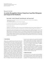
−240
−220
−200
−180
−160
−140
Field amplitude (dB)
0 5 10 15 20 25 30 35 40
Iteration
Figure 3: Convergence of the iterative approximation of line source
in vertical polarization with k
z
= 0, I
z
= 1×10
−10
Aat2.45GHz,the
source position: ρ
s
= 15 cm, φ
s
= 90
◦
, and the observation position:
ρ
= 15 cm, φ = 270
◦
.
This algorithm provides a consistent structure of the
scattered fields over successive iterations expressed as
Γ
p|(k)
m
= Λ
−1
mp
G
mp
+
K
k=1
Θ
k
,
Θ
k
=
1
Λ
−1
mp
F
nq
mp
···
k
Λ
−1
n
k−2
q
k−2
F
n
k−1
q
k−1
n
k−2
q
k−2
Γ
q|(1)
n
,
k
=
∞
n
k−1
=−∞
P
q
k−1
/
=q
k−2
.
(17)
The performance of the iterative algorithm is further
validated by a simulation sample at 2.45 GHz, considering a
vertically polarized line source with k
z
= 0, I
z
= 1 ×10
−10
A,
ρ
s
= 15cm, φ
s
= 90
◦
, located on the trunk surface (r
body
=
14.5cm, r
arm
= 3.8cm, d
ab
= 3cm). The convergence
of the total field amplitude in dB scale at the observation
point, φ
s
= 270
◦
, ρ = 15 cm, is provided in Figure 3.The
results show a stable convergence of the field power after
15 iterations. In practice, the number of iteration is selected
to be sufficiently large number (
≥10) that all the interested
fields can converge to a stable level.
Figure 4 compares the final field solution, for both single
cylinder (only trunk) and multiple cylinder scattering (with
arms pending down along the sides of the trunk as in
Figure 2(c)), and for a point source with tangential (z)
or normal (ρ) polarizations in the azimuth plane around
the trunk. The results show that for on-body channels on
the trunk surface, the dominant part of the total field is
determined by the incident field from the source and the
scattering from the trunk, while the presence of arm scatter-
ing causes channels to fluctuate around this average value.
This fluctuation varies with respect to different positions
of the arms, which will generate the time-variant channel
fading when in dynamic scenarios as will be discussed later.
The difference between the fields for both polarizations is
clear: on-body channels with tangential z-polarization have
a much higher path loss around the trunk, and the arm
scattering brings a larger power fluctuation. The polarization
EURASIP Journal on Wireless Communications and Networking 7
−200
−180
−160
−140
−120
−100
|E
ρ
| (dB)
100 200 300
Normal (ρ) polarization
φ (deg)
Single cylinder scattering
Multiple cylinder scattering
(a)
−200
−180
−160
−140
−120
−100
|E
ρ
| (dB)
100 200 300
Ta ng en ti al ( z) polarization
φ (deg)
Single cylinder scattering
Multiple cylinder scattering
(b)
Figure 4: Simulation comparison of the field amplitude (dB) between single cylinder scattering and multiple cylinder scattering of a point
source with I
= 10
−10
Ainz and ρ polarizations at 2.45 GHz around the trunk (r
body
= 15.4cm,r
arm
= 3.5cm,d
ab
= 3.5cm,d
s
= 1cm).The
source is placed at ρ
s
= 15 cm, φ
s
= 90
◦
and the fields are computed at ρ = 15 cm, φ = [0 − 360]
◦
.
is expected to have similar effects on the properties of the on-
body channel dynamics scenarios, for example on the path
loss and variance of the channel fading.
4.4. Dynamic Body Scattering Modeling. The dynamic body
scattering is an extension of the above field solution obtained
by incorporating the time evolution of the positions of the
cylinders in the azimuth plane to simulate the arm swing
during walk. In this model, we consider simple periodic trace
functions T
l
(t)andT
r
(t) along the y direction to describe the
left and right arm swing in Figure 2(c). The positions of the
cylinders representing the arms are then expressed as
x
l
(
t
)
, y
l
(
t
)
=
−
r
arm
+ r
body
+ d
ab
, T
l
(
t
)
,
x
r
(
t
)
, y
r
(
t
)
=
r
arm
+ r
body
+ d
ab
, T
r
(
t
)
,
(18)
where [x
l
, y
l
]and[x
r
, y
r
] are the left and right arm central.
In our work, T
l
(t)andT
r
(t)aresampledbytracinga
marker attached on the swinging arms of a male volunteer
as in Figure 5(a). A digital camera recorded the arm swing
at 30 frames per second. The averaged arm trace over one
cycle is normalized into 1 s. The amplitude and the time
variation of the trace functions determines most of the time-
variant properties of the channel fading like the variance
and deterministic waveform, hence they should be carefully
selected. The considered trace functions in the simulations
are shown in Figure 5(b). Usually, the synthesized time-
variant fields have to be synchronized with realistic mea-
surement observations so the field variation, that is, the
local peaks of the fields along the time are matched with
corresponding local peaks in measurement observations.
5. Model Validation
Our model was validated by measurements that were
conducted in anechoic environment at 2.45 GHz, that is,
one of the standard ISM bands for WBANs. Three small-
sized antennas were fixed on the trunk surface of a male
volunteer, with antenna 1 as the Tx and antennas 2 and 3
as the Rx. Two on-body channels are then formed, noted
as S
21
and S
31
. The volunteer kept a standing posture
throughout the measurements and only swung the arms to
mimic the arm movements during walk. We used vector
network analyzers (VNAs) to measure the transmission S-
parameters of the antennas as the channel measurements. A
single measurement campaign given specific locations and
polarizations of the antennas lasted for 10 s. The details of
the measurements are provided in Table 1.
8 EURASIP Journal on Wireless Communications and Networking
Marker
T
l/r
(a) Arm swing recording scenario by tracing a black
marker on the arms
−20
−10
0
10
20
30
(cm)
00.20.40.60.81
Time (s)
Right T
r
(t)
Left T
l
(t)
(b) The normalized trace functions over one cycle
Figure 5: The arm swing modeling.
Table 1: Measurement setup.
External environment: anechoic
Number of antennas: 3
Measurement length: 10 s
Sampling rate: 1 ms
Human body: male, 183 cm/78 kg
r
body
= 14.2cm,r
arm
= 4.5cm,d
ab
=3cm
Body dynamics: standing & arm swinging
Propagation range: front side of the trunk
Polarization: vertical & normal to the trunk surface
We extracted the statistics of the measured on-body
channels based on each measurement campaign (10 s), which
are further related with their geometric description.
The simulations of the model reproduced the measure-
ment scenarios. The simulated channels are calculated by
normalizing the field solution as
S
xy
=
E
x
E
y
,
(19)
where E
x
is the E-field at the Rx and E
y
is the E-field at a
position quite close to the source. Both the deterministic time
variation and the statistics of the on-body channels will be
compared between the measurements and the corresponding
simulations to evaluate the their similarities in different
scenarios.
5.1. Tangential z-Polarization Scenarios. In the tangential z-
polarization scenarios, three patch antennas (Skycross SMT-
3TO10M) with z-polarization were placed around the trunk
as in Figure 5.1. The antennas were placed 0.5 cm away from
the trunk surface in order to mitigate the body coupling
effect to the antenna efficiency. Each channel is geometrically
characterized by means of the Tx position relative to the
trunk center, noted as d
10
, and the Tx-Rx propagation
32
1
0
Figure 6: Tangential z-polarization scenarios. 1, 2, 3 designate the
antenna allocations and 0 is the trunk center point.
distances measured on the trunk surface, denoted as d
12
and
d
13
. Propagation takes place in the azimuth (i.e., horizontal)
plane from the left to the right sides of the trunk, as depicted
in Figure 5.1.
The temporal fading behavior is illustrated in Figure 7,
where a measurement sample of channel S
21
with d
10
=
19 cm and d
12
= 14 cm is compared with the corresponding
simulation. The simulation successfully matches the local
peaks of the fading amplitude over the cycle and maintains
a small mean squared error (MSE) of 1.21 dB with respect to
the measurement. Both measurement and simulation show
a symmetric waveform in the first and in the second half
period, which is consistent with the regular arm swing.
However, the simulated results usually display a larger
dynamic variance. A possible explanation is that, given
the cylindrical shape of the modeled trunk, simulations
underestimate the invariant part of the channel given by the
combination of the incident field and the trunk scattering,
which implies that the dynamic part of the channel resulting
from arm scattering is relatively increased in dB scale.
EURASIP Journal on Wireless Communications and Networking 9
−5
0
5
Amplitude (dB)
00.20.40.60.81
Time (s)
Measurement
Simulation
Figure 7: Waveform comparison of the normalized channel fading
amplitude (dB) over one period with one measurement of S
12
(d
10
=
19 cm, d
12
= 19 cm).
On-body fading statistics extracted from simulations
and measurements are compared in Figures 8(a) and 8(b),
respectively, for the mean, μ, and the standard deviation
(std), σ of the fading amplitude in dB scale. At a specific
propagation distance, the experimental spread is caused by
different values d
10
. For clarity, we only plot the average of the
simulated values at each investigated propagation distance.
In Figure 8(a),thesimulatedmeanμ successfully fits the
measurements, showing that the path loss around the trunk
in tangential z-polarization is about 1.68 dB/cm. In Fig-
ure 8(b), the simulation results also reproduce the increasing
trend of σ observed in the measurements up to 15 cm. When
the propagation distance is above 15 cm, the larger simulated
value of σ can again be explained by the weakening effect of
the simulated invariant channel around the trunk.
The channel correlation between S
21
and S
31
is inves-
tigated by computing the correlation coefficient of their
amplitudes in dB scale, defined as:
ρ
21,31
=
E
|
S
21
|
dB
−μ
|S
21
|
dB
|
S
31
|
dB
−μ
|S
31
|
dB
σ
|S
21
|
dB
σ
|S
31
|
dB
.
(20)
According to Figure 5.1, ρ
21,31
is related to the distance
between antennas 2 and 3, d
23
, that is the distance difference
that causes the decorrelation of the two channels. In Figure 9,
ρ
21,31
of two series of measurements with d
12
= 12 and
d
12
= 14 cm are compared with the simulations, respectively.
The simulation results predict a close decreasing trend of the
average ρ
21,31
as afunction of d
23
, as experimentally observed.
5.2. Normal Polarization Scenarios. Measurements in the
normal (ρ) polarization scenarios employed three-folded
dipole antennas with normal polarization to the trunk
surface. As the poles of the antenna were now pointing
towards the trunk surface, the distance from the antennas to
the skin was increased to 1.75 cm. In the normal polarization
scenarios, the model was evaluated along two dimensions
as depicted in Figure 10.InFigure10(a), the antennas are
placed around the trunk to form horizontal transmissions
−100
−80
−60
−40
−20
0
μ (dB)
0 5 10 15 20 25
Propagation distance (cm)
Measurement
Simulation
(a) μ comparison
0
0.5
1
1.5
2
2.5
3
3.5
4
μ (dB)
0 5 10 15 20 25
Propagation distance (cm)
Measurement
Simulation
(b) σ comparison
Figure 8: Comparisons of the mean (μ)andstd(σ) of the channel
fading amplitude (dB) for on-body channels around the trunk in
tangential z-polarization.
from the right to the left sides of the trunk. In Figure 10(b),
the antennas are placed along a vertical line on the trunk
to form vertical on-body channels. The positions of these
channels are still described by the distance from the antenna
1tothetrunkcenter(d
10
), as noted in Figure 10(b).The
propagation distances, d
12
and d
13
, are then measured in the
vertical direction.
The measured temporal fading dynamics in normal
polarization scenarios are expected to deviate from simu-
lations mainly for two reasons: (1) the dipole antenna in
normal polarization contains current distributed along the
normal direction, which results in much more complicated
arm scattering effects and is not well approximated by a point
source at a certain ρ
s
; (2) the propagation along the vertical
direction will get closer to the edge of the body (towards
the head), thereby violating the infinite cylinder assumption.
Subsequently, the comparisons in the normal polarization
scenario are focused on statistical comparisons only.
5.2.1. Horizontal Propagation. Parameters μ and σ,extracted
from both measurements and simulations, are compared in
Figures 11(a) and 11(b), respectively. The mean μ is well
predicted by the simulations, showing an average path loss
10 EURASIP Journal on Wireless Communications and Networking
−0.5
0
0.5
1
ρ
21,31
0 5 10 15 20 25 30
Distance difference d
23
(cm)
d
12
= 12 cm
Measurement
Simulation
(a) d
12
= 12 cm
−0.5
0
0.5
1
ρ
21,31
0 5 10 15 20 25 30
Distance difference d
23
(cm)
d
12
=14 cm
Measurement
Simulation
(b) d
12
= 14 cm
Figure 9: Comparisons of channel fading amplitude (dB) correlation coefficient ρ
21,31
for tangential z-polarization scenarios around the
trunk with different lengths of d
12
.
3
2
1
0
(a) Horizontal propagation
3
2
1
0
d
10
(b) Vertical propagation
Figure 10: Two dimensions of propagation in the normal polarization scenario.
−50
−45
−40
−35
−30
−25
−20
−15
−10
μ (dB)
0 5 10 15 20 25
Propagation distance (cm)
Measurement
Simulation
(a) μ comparisons
0
0.5
1
1.5
2
σ (dB)
0 5 10 15 20 25
Propagation distance (cm)
Measurement
Simulation
(b) σ comparisons in scenarios where d
12
= 12 cm
Figure 11: Comparisons of the mean (μ)andstd(σ) of the channel fading amplitude (dB) for on-body channels around the trunk
(horizontal direction) with normal polarization.
EURASIP Journal on Wireless Communications and Networking 11
0
0.2
0.4
0.6
0.8
1
ρ
21,31
0 5 10 15 20 25
Distance difference d
23
(cm)
Measurement
Simulation
Figure 12: Comparison of the channel fading amplitude (dB)
correlation coefficient, ρ
21,31
for normal polarization scenarios
around the trunk with d
10
= 12 cm and d
12
= 7cm.
of 1.1 dB/cm around the trunk in normal polarization. The
comparison on σ in Figure 8(b) is based on a series of
measurements with d
12
= 12 cm and the corresponding
simulations. Again, σ increases with the distance in both
simulated and measured results. The difference between
Figures 8 and Figure 11 highlights the impact of different
polarizations on the fading statistics.
The channel correlation coefficient ρ
21,31
,asdefinedby
(20), is plotted in Figure 12 for a series of measurements
with d
10
= 12 cm, d
12
= 7 cm, and for the corresponding
simulations. The comparison shows a consistent decreasing
trend of ρ
21,31
against d
23
.TheresultsofFigures9 and 12
illustrate that, for on-body propagation around the trunk
in both tangential z- and normal polarizations, the distance
difference d
23
of the overlapped channels S
21
and S
31
is the
main decorrelation parameter.
5.2.2. Vertical Propagation. Figures 13(a) and 13(b),respec-
tively, compare simulated and measured values of μ and
σ. The simulation again provides a good prediction of μ,
with an average path loss of 0.6 dB/cm for vertical on-body
channels in normal polarization. These results also validate
that the path loss of the propagation along the trunk is
much lower than the path loss of the propagation around
the trunk in normal polarization scenarios. Such difference
is the result of a much stronger LOS condition for on-body
channels propagating along the trunk. Consequently, it also
increases the invariant part of the on-body channel, thereby
yielding a smaller variance than in horizontal transmissions.
In the measurements, the rotation of the arms during the arm
swing causes a larger scattering effect to the vertical channels
than the perfectly parallel arms assumed in the model. This
explains the overall higher level of measured σ above 20 cm
in Figure 13(b). Yet, the agreement is better below 20 cm.
The comparison of the channel correlation is not made
since the measured range along the vertical direction is too
limited to obtain relevant results.
−40
−35
−30
−25
−20
−15
−10
μ (dB)
0 5 10 15 20 25
Propagation distance (cm)
Measurement
Simulation
(a) μ comparison
0
0.5
1
1.5
2
σ (dB)
0 5 10 15 20 25
Propagation distance (cm)
Measurement
Simulation
(b) σ comparison with d
10
= 12 cm
Figure 13: Comparisons of the mean (μ)andstd(σ)ofthe
channel fading amplitude (dB) for on-body channels along the
trunk (vertical direction) in normal polarization.
6. Conclusions
In this paper, we developed an analytical model of on-
body transmissions on the trunk of a walking human.
We investigated the impact of the antenna locations and
polarizations, as well as of the body posture and motion. The
dynamic scattering from the arms was analyzed with a simple
description of the arm movements. A general full-wave
solution of the multiple cylinder scattering by a polarized
point source was derived and extended by considering time
evolution. By comparisons with different measurements at
2.45 GHz, it was shown that the model successfully predicts
both deterministic and stochastic aspects of the dynamic
fading behavior for tangentially polarized antennas. For
normally polarized antennas, only a statistical comparison
was carried out, and successfully validated the model for
horizontal (around the trunk) and vertical (along the trunk)
transmissions. In the latter, however, the application of the
model is limited to ranges below 20 cm, owing to the infinite
cylinder assumption.
Our results further highlight the importance of a proper
description of the arm motion, and the significant impact
12 EURASIP Journal on Wireless Communications and Networking
of the antenna polarization. The performance of our model
is restricted by the infinite cylinder approximation, and the
small scale of the arm swinging, so that the parallel motion
assumption in the azimuth plane holds true. Furthermore,
the antennas should be small enough to be well approx-
imated by a point source. Note that the model was also
validated at other frequencies in [4, 5].
Acknowledgments
This work was financed by the R
´
egion Wallone in the
framework of research contract 616449 WALIBI within
the WIST-2 program. This work was also carried out in
the framework of the COST 2100 Action. The authors
wouldalsoliketothankDr.St
´
ephane Van Roy from the
OPERA, Universit
´
e Libre de Bruxelles (ULB), Belgium, and
the WELCOME facility of Universit
´
e catholique de Louvain
(UCL), Belgium for their technical support.
References
[1] M. Patel and J. Wang, “Applications, challenges, and prospec-
tive in emerging body area networking technologies,” IEEE
Wireless Co mmunications, vol. 17, no. 1, pp. 80–88, 2010.
[2] E. Mont
´
on,J.F.Hernandez,J.M.Blascoetal.,“Bodyareanet-
work for wireless patient monitoring,” IET Communications,
vol. 2, no. 2, pp. 215–222, 2008.
[3] S. C. Ergen, “ZigBee/IEEE 802.15.4 summary,” Tech. Rep.,
Advanced Technology Lab of National Semiconductor, 2004.
[4] L.Liu,S.VanRoy,P.DeDoncker,andC.Oestges,“Azimuth
radiation pattern characterization of omnidirectional anten-
nas near a human body,” in Proceedings of the Interna-
tional Conference on Electromagnetics in Advanced Applications
(ICEAA ’09), pp. 461–464, September 2009.
[5] S.VanRoy,L.Liu,C.Oestges,andP.DeDoncker,“Anultra-
wideband sage algorithm for body area networks,” in Pro-
ceedings of the International Conference on Electromagnetics in
Advanced Applications (ICEAA ’09), pp. 584–587, September
2009.
[6] K. Y. Yazdandoost and K. Hamaguchi, “Antenna polariza-
tion mismatch in body area network communications,” in
Proceedings of the 4th European Conference on Antennas and
Propagation (EuCAP ’10), pp. 1–4, 2010.
[7]A.Fort,C.Desset,J.Ryckaert,P.DeDoncker,L.Van
Biesen, and S. Donnay, “Ultra wide-band body area channel
model,” in Proceedings of the IEEE International Conference on
Communications (ICC ’05), pp. 2840–2844, May 2005.
[8] A.Molisch,D.Cassioli,C C.Chongetal.,“Acomprehensive
standardized model for ultrawideband propagation channels,”
IEEE Transactions on Antennas and Propagation, vol. 54, no. 11,
pp. 3151–3166, 2006.
[9] Y. Hao, A. Alomainy, Y. Zhao et al., “Statistical and determinis-
tic modelling of radio propagation channels in WBAN at 2.45
GHz,” in Proceedings of the IEEE Antennas and Propagation
Society International Symposium (APS ’06), pp. 2169–2172,
July 2006.
[10] L. Liu, P. De Doncker, and C. Oestges, “Fading correlation
measurement and modeling on the front side of a human
body,” in Proceedings of the 3rd European Conference on
Antennas and Propagation (EuCAP ’09), pp. 969–973, March
2009.
[11] E. Reusens, W. Joseph, G. Vermeeren et al., “Path loss models
for wireless communication channel along arm and Torso:
Measurements and simulations,” in Proceedings of the IEEE
Antennas and Propagation Society International Symposium,
pp. 345–348, June 2007.
[12] Y. Zhao, A. Sani, Y. Hao, S L. Lee, and G Z. Yang, “A
simulation environment for subject-specific radio channel
modeling in wireless body sensor networks,” in Proceedings of
the 6th International Workshop on Wearable and Implantable
Body Sensor Networks (BSN ’09), pp. 23–28, 2009.
[13] A. Fort, F. Keshmiri, G. R. Crusats, C. Craeye, and C. Oestges,
“A body area propagation model derived from fundamental
principles: Analytical analysis and comparison with mea-
surements,” IEEE Transactions on Antennas and Propagation,
vol. 58, no. 2, pp. 503–514, 2010.
[14] A. Gupta and T. D. Abhayapala, “Body Area Networks: radio
channel modelling and propagation characteristics,” in Pro-
ceedings of the Australian Communications Theory Workshop
(AusCTW ’28), pp. 58–63, 2008.
[15] D. Ma and W. X. Zhang, “Analytic propagation model for
body area network channel based on impedance boundary
condition,” in Proceedings of the 3rd European Conference on
Antennas and Propagation (EuCAP ’09), pp. 974–978, March
2009.
[16] Y. Chen, J. Teo, J. Lai et al., “Cooperative communications
in ultra-wideband wireless body area networks: channel
modeling and system diversity analysis,” IEEE Journal on
Selected Areas in Communications, vol. 27, no. 1, pp. 5–16,
2009.
[17] P. S. Hall and Y. Hao, Antennas and Propagation for Bo dy-
Centric Wireless Communications, Artech House, Norwood,
Mass, USA, 2006.
[18] A. Z. Elsherbeni, “Comparative study of two-dimensional
multiple scattering techniques,” Radio Science, vol. 29, no. 4,
pp. 1023–1033, 1994.
[19] R. W. Scharstein, “Acoustic scattering from two parallel soft
cylinders,” in Proceedings of the IEEE Southeastcon, pp. 534–
537, April 1992.
[20] W. C. Chew, Waves and Fields in Inhomogeneous Media, IEEE
Press, New York, NY, USA, 1995.
[21] F. Keshmiri and C. Craeye, “Wave propagation from sources
with arbitrary polarization next to the human body,” in
Proceedings of the IEEE International Symposium on Antennas
and Propagation and the USNC/URSI National Radio Science
Meeting, 2010.
[22]A.Fort,L.Liu,F.Keshmiri,P.DeDoncker,C.Oestges,and
C. Craeye, “Analysis of wave propagation including shadow
fading correlation for BAN applications,” in Proceedings of
the 2nd IET Seminar on Antennas and Propagation for Body-
Centric Wireless Communications, vol. 2009, pp. 1–28, 2009.
[23] M.Abramowitz,I.A.Stegun,andP.M.Morse,Handbook of
Mathematical Functions, GPO, 1964.
[24] G. N. Watson,, Theor y of Bessel Functions,CambridgeUniver-
sity Press, Cambridge, UK, 1922.