Mechatronic Systems, Simulation, Modeling and Control Part 1 potx
Bạn đang xem bản rút gọn của tài liệu. Xem và tải ngay bản đầy đủ của tài liệu tại đây (587.69 KB, 18 trang )
I
Mechatronic Systems, Simulation,
Modelling and Control
Mechatronic Systems, Simulation,
Modelling and Control
Edited by
Annalisa Milella, Donato Di Paola
and Grazia Cicirelli
In-Tech
intechweb.org
Published by In-Teh
In-Teh
Olajnica 19/2, 32000 Vukovar, Croatia
Abstracting and non-prot use of the material is permitted with credit to the source. Statements and
opinions expressed in the chapters are these of the individual contributors and not necessarily those of
the editors or publisher. No responsibility is accepted for the accuracy of information contained in the
published articles. Publisher assumes no responsibility liability for any damage or injury to persons or
property arising out of the use of any materials, instructions, methods or ideas contained inside. After
this work has been published by the In-Teh, authors have the right to republish it, in whole or part, in any
publication of which they are an author or editor, and the make other personal use of the work.
© 2010 In-teh
www.intechweb.org
Additional copies can be obtained from:
First published March 2010
Printed in India
Technical Editor: Sonja Mujacic
Cover designed by Dino Smrekar
Mechatronic Systems, Simulation, Modelling and Control,
Edited by Annalisa Milella, Donato Di Paola and Grazia Cicirelli
p. cm.
ISBN 978-953-307-041-4
V
Preface
Mechatronics, the synergistic blend of mechanics, electronics, and computer science, has
evolved over the past twenty-ve years, leading to a novel stage of engineering design. By
integrating the best design practices with the most advanced technologies, mechatronics aims
at realizing highquality products, guaranteeing, at the same time, a substantial reduction of
time and costs of manufacturing. Mechatronic systems are manifold, and range from machine
components, motion generators, and power producing machines to more complex devices,
such as robotic systems and transportation vehicles. With its 15 chapters, which collect
contributions from many researchers worldwide, this book provides an excellent survey of
recent work in modelling and control of electromechanical components, and mechatronic
machines and vehicles.
A brief description of every chapter follows. The book begins with eight chapters related
to modelling and control of electromechanical machines and machine components. Chapter
1 presents an electromechanical model for a ring-type Piezoelectric Transformer (PT). The
presented model provides a general framework capable of serving as a design tool for
optimizing the conguration of a PT. Chapter 2 develops a current harmonic model for high-
power synchronous machines. The use of genetic algorithm-based optimization techniques
is proposed for optimal PWM. Chapter 3 deals with the control of a servo mechanism
with signicant dry friction. The proposed procedure for system structure identication,
modelling, and parameter estimation is applicable to a wide class of servos. The solution is
described in detail for a particular actuator used in the automotive industry, i.e., the electronic
throttle. Chapter 4 proposes a diagram of H∞ regulation, linked to the eld oriented control,
that allows for a correct transient regime and good robustness against parameter variation
for an induction motor. In Chapter 5, a pump-displacement-controlled actuator system with
applications in aerospace industry is modelled using the bond graph methodology. Then,
an approach is developed towards simplication and model order reduction for bond graph
models. It is shown that using a bond graph model, it is possible to design fault detection
and isolation algorithms, and to improve monitoring of the actuator. A robust controller
for a Travelling Wave Ultrasonic Motor (TWUM) is described in Chapter 6. Simulation and
experimental results demonstrate the effectiveness of the proposed controller in extreme
operating conditions. Chapter 7 introduces a resonance frequency tracing system without the
loop lter based on digital Phase Locked Loop (PLL). Ultrasonic dental scalar is presented as
an example of application of the proposed approach. Chapter 8 presents the architecture of
the Robotenis system composed by a robotic arm and a vision system. The system tests joint
control and visual servoing algorithms. The main objective is to carry out tracking tasks in
three dimensions and dynamical environments.
VI
Chapters 9-11 deal with modelling and control of vehicles. Chapter 9 concerns the design
of motion control systems for helicopters, presenting a nonlinear model for the control of
a three-DOF helicopter. A helicopter model and a control method of the model are also
presented and validated experimentally in Chapter 10. Chapter 11 introduces a planar
laboratory testbed for the simulation of autonomous proximity manoeuvres of a uniquely
control actuator congured spacecraft.The design of complex mechatronic systems requires
the development and use of software tools, integrated development environments, and
systematic design practices. Integrated methods of simulation and Real-Time control aiming
at improving the efciency of an iterative design process of control systems are presented
in Chapter 12. Reliability analysis methods for an embedded Open Source Software (OSS)
are discussed in Chapter 13. A new specication technique for the conceptual design of
mechatronic and self-optimizing systems is presented in Chapter 14. The railway technology
is introduced as a complex example, to demonstrate how to use the proposed technique, and
in which way it may contribute to the development of future mechanical engineering systems.
Chapter 15 provides a general overview of design specicities including mechanical and
control considerations for micro- mechatronic structures. It also presents an example of a new
optimal synthesis method, to design topology and associated robust control methodologies
for monolithic compliant microstructures.
Annalisa Milella, Donato Di Paola and Grazia Cicirelli
VII
Contents
Preface V
1. ElectromechanicalAnalysisofaRing-typePiezoelectricTransformer 001
Shine-TzongHo
2. GeneticAlgorithm–BasedOptimalPWMinHighPowerSynchronous
MachinesandRegulationofObservedModulationError 017
AlirezaRezazade,ArashSayyahandMitraAaki
3. ModellingandControlofElectromechanicalServoSystem
withHighNonlinearity 045
Grepl,R.
4. RobustShapingIndirectFieldOrientedControlforInductionMotor 059
M.Boukhnifer,C.LarouciandA.Chaibet
5. ModelingandFaultDiagnosisofanElectrohydraulicActuatorSystemwitha
MultidisciplinaryApproachUsingBondGraph 073
M.H.Toughi,S.H.SadatiandF.Naja
6. RobustControlofUltrasonicMotorOperatingunderSevere
OperatingConditions 089
MoussaBoukhnifer,AntoineFerreiraandDidierAubry
7. ResonanceFrequencyTracingSystemforLangevin
TypeUltrasonicTransducers 105
YutakaMaruyama,MasayaTakasakiandTakeshiMizuno
8. NewvisualServoingcontrolstrategiesintrackingtasksusingaPKM 117
A.Traslosheros,L.Angel,J.M.Sebastián,F.Roberti,R.CarelliandR.Vaca
9. NonlinearAdaptiveModelFollowingControlfora3-DOFModelHelicopter 147
MitsuakiIshitobiandMasatoshiNishi
10. ApplicationofHigherOrderDerivativestoHelicopterModelControl 173
RomanCzybaandMichalSeran
11. LaboratoryExperimentationofGuidanceandControlofSpacecraft
DuringOn-orbitProximityManeuvers 187
JasonS.HallandMarcelloRomano
VIII
12. IntegratedEnvironmentofSimulationandReal-TimeControlExperiment
forControlsystem 223
KentaroYanoandMasanobuKoga
13. ReliabilityAnalysisMethodsforanEmbeddedOpenSourceSoftware 239
YoshinobuTamuraandShigeruYamada
14. ArchitectureandDesignMethodologyofSelf-OptimizingMechatronicSystems 255
Prof.Dr Ing.JürgenGausemeierandDipl Wirt Ing.SaschaKahl
15. ContributionstotheMultifunctionalIntegrationforMicromechatronicSystems 287
M.GrossardMathieuandM.ChailletNicolas
ElectromechanicalAnalysisofaRing-typePiezoelectricTransformer 1
ElectromechanicalAnalysisofaRing-typePiezoelectricTransformer
Shine-TzongHo
x
Electromechanical Analysis of a
Ring-type Piezoelectric Transformer
Shine-Tzong Ho
Kaohsiung University of Applied Sciences
Taiwan
1. Introduction
The idea of a piezoelectric transformer (PT) was first implemented by Rosen (Rosen, 1956),
as shown in Fig.1. It used the coupling effect between electrical and mechanical energy of
piezoelectric materials. A sinusoidal signal is used to excite mechanical vibrations by the
inverse piezoelectric effect via the driver section. An output voltage can be induced in the
generator part due to the direct piezoelectric effect. The PT offers many advantages over the
conventional electromagnetic transformer such as high power-to-volume ratio,
electromagnetic field immunity, and nonflammable.
Due to the demand on miniaturization of power supplying systems of electrical equipment,
the study of PT has become a very active research area in engineering. In literatures (Sasaki,
1993; Bishop, 1998), many piezoelectric transformers have been proposed and a few of them
found practical applications. Apart from switching power supply system, a Roson-type PT
has been adopted in cold cathode fluorescent lamp inverters for liquid-crystal display. The
PT with multilayer structure to provide high-output power may be used in various kinds of
power supply units. Recently, PT of ring (Hu, 2001) or disk (Laoratanakul, 2002) shapes
have been proposed and investigated. Their main advantages are simple structure and
small size. In comparing with the structure of a ring and a disk, the PZT ring offers higher
electromechanical coupling implies that a ring structure is more efficient in converting
mechanical energy to electrical energy, and vice versa, which is essential for a high
performance PT.
Different from all the conventional PT, the ring-type PT requires only a single poling process
and a proper electrode pattern, and it was fabricated by a PZT ring by dividing one of the
electrodes into two concentric circular regions. Because of the mode coupling effect and the
complexity of vibration modes at high frequency, the conventional lumped-equivalent
circuit method may not accurately predict the dynamic behaviors of the PT.
In this chapter, an electromechanical model for a ring-type PT is obtained based on
Hamilton’s principle. In order to establish the model, vibration characteristics of the
piezoelectric ring with free boundary conditions are analyzed in advance, and the natural
frequencies and mode shapes are obtained. In addition, an equivalent circuit model of the
PT is obtained based on the equations of the motion for the coupling electromechanical
system. Furthermore, the voltage step-up ratio, input impedance, output impedance, input
1
MechatronicSystems,Simulation,ModellingandControl2
power, output power, and efficiency for the PT will be conducted. Then, the optimal load
resistance and the maximum efficiency for the PT will be calculated.
Fig. 1. Structure of a Rosen-type piezoelectric transformer.
Fig. 2. Structure of a ring-type piezoelectric transformer.
2. Theoretical Analysis
2.1 Vibration Analysis of the Piezoelectric Ring
Fig.2 shows the geometric configuration of a ring-type PT with external radius R
o
, internal
radius R
i
, and thickness h. The ring is assumed to be thin, h << R
i
. The cylindrical coordinate
system is adopted where the r-θ plane is coincident with the mid-plane of the undeformed
ring, and the origin is in the center of the ring. The piezoelectric ring is polarized in the
thickness direction, and two opposite surfaces are covered by electrodes. The constitutive
equations for a piezoelectric material with crystal symmetry class C
6v
can be expressed as
follows.
z
r
r
zr
z
z
r
E
E
E
EEE
EEE
EEE
r
zr
z
z
r
E
E
E
d
d
d
d
d
s
s
s
sss
sss
sss
000
00
00
00
00
00
00000
00000
00000
000
000
000
15
15
33
31
31
66
44
44
331313
131112
131211
(1a)
z
r
T
T
T
r
zr
z
z
r
z
r
E
E
E
ddd
d
d
D
D
D
33
11
11
333131
15
15
00
00
00
000
00000
00000
(1b)
where σ
r
, σ
θ
, σ
z
, τ
θz
, τ
zr
, τ
θr
are the components of the stress, ε
r
, ε
θ
, ε
z
, γ
θz
, γ
zr
, γ
θr
are the
components of the strain, and all the components are functions of r, θ, z, and t. s
11
E
, s
12
E
, s
13
E
,
s
33
E
, s
44
E
, s
66
E
are the compliance constants, d
15
, d
31
, d
33
are the piezoelectric constants, ε
11
T
, ε
33
T
are the dielectric constants, D
r
, D
θ
, D
z
are the components of the electrical displacement, and
E
r
, E
θ
, E
z
are the components of the electrical field. The piezoelectric material is isotropic in
the plane normal to the z-axis. The charge equation of electrostatics is represented as:
0
11
z
D
D
r
D
rr
D
z
r
r
(2)
The electric field-electric potential relations are given by:
r
E
r
,
r
E
1
,
z
E
z
,
(3)
where φ is the electrical potential. The differential equations of equilibrium for three-
dimensional problems in cylindrical coordinates are:
2
2
1
t
u
rzrr
rrzrrr
,
(4a)
ElectromechanicalAnalysisofaRing-typePiezoelectricTransformer 3
power, output power, and efficiency for the PT will be conducted. Then, the optimal load
resistance and the maximum efficiency for the PT will be calculated.
Fig. 1. Structure of a Rosen-type piezoelectric transformer.
Fig. 2. Structure of a ring-type piezoelectric transformer.
2. Theoretical Analysis
2.1 Vibration Analysis of the Piezoelectric Ring
Fig.2 shows the geometric configuration of a ring-type PT with external radius R
o
, internal
radius R
i
, and thickness h. The ring is assumed to be thin, h << R
i
. The cylindrical coordinate
system is adopted where the r-θ plane is coincident with the mid-plane of the undeformed
ring, and the origin is in the center of the ring. The piezoelectric ring is polarized in the
thickness direction, and two opposite surfaces are covered by electrodes. The constitutive
equations for a piezoelectric material with crystal symmetry class C
6v
can be expressed as
follows.
z
r
r
zr
z
z
r
E
E
E
EEE
EEE
EEE
r
zr
z
z
r
E
E
E
d
d
d
d
d
s
s
s
sss
sss
sss
000
00
00
00
00
00
00000
00000
00000
000
000
000
15
15
33
31
31
66
44
44
331313
131112
131211
(1a)
z
r
T
T
T
r
zr
z
z
r
z
r
E
E
E
ddd
d
d
D
D
D
33
11
11
333131
15
15
00
00
00
000
00000
00000
(1b)
where σ
r
, σ
θ
, σ
z
, τ
θz
, τ
zr
, τ
θr
are the components of the stress, ε
r
, ε
θ
, ε
z
, γ
θz
, γ
zr
, γ
θr
are the
components of the strain, and all the components are functions of r, θ, z, and t. s
11
E
, s
12
E
, s
13
E
,
s
33
E
, s
44
E
, s
66
E
are the compliance constants, d
15
, d
31
, d
33
are the piezoelectric constants, ε
11
T
, ε
33
T
are the dielectric constants, D
r
, D
θ
, D
z
are the components of the electrical displacement, and
E
r
, E
θ
, E
z
are the components of the electrical field. The piezoelectric material is isotropic in
the plane normal to the z-axis. The charge equation of electrostatics is represented as:
0
11
z
D
D
r
D
rr
D
z
r
r
(2)
The electric field-electric potential relations are given by:
r
E
r
,
r
E
1
,
z
E
z
,
(3)
where φ is the electrical potential. The differential equations of equilibrium for three-
dimensional problems in cylindrical coordinates are:
2
2
1
t
u
rzrr
rrzrrr
,
(4a)
MechatronicSystems,Simulation,ModellingandControl4
2
2
21
t
u
rzrr
rzr
,
(4b)
2
2
1
t
u
rzrr
zzrzzzr
,
(4c)
where u
r
(r,θ,z,t), u
θ
(r,θ,z,t), u
z
(r,θ,z,t) are the displacements of the ring in the radial, tangential,
and transverse direction, respectively. And ρ is the material density. The strain-
displacement relations for three-dimensional problems in cylindrical coordinates are given
by:
r
u
r
r
,
u
rr
u
r
1
,
z
u
z
z
,
(5a)
r
u
r
uu
r
r
r
1
,
(5b)
z
z
u
rz
u 1
,
(5c)
z
u
r
u
rz
zr
.
(5d)
Because the piezoelectric disk is thin and the deformation is small, the kirchoff assumption
is made. The kirchoff assumptions are as follows:
r
trw
ztrutzru
r
),,(
),,(),,,(
0
0
,
(6)
r
trw
r
z
trvtzru
),,(
),,(),,,(
0
0
,
(7)
),,(),,,(
0
trwtzru
z
,
(8)
where u
0
, v
0
, w
0
represent the radial, the tangential, and the transverse displacements of the
middle surface of the plane, respectively. After inserting (6)-(8) into (5a), (5b), the strain-
displacement relations can be obtained as:
2
0
2
0
r
w
z
r
u
r
u
r
r
,
(9a)
0000
111
w
rr
w
z
v
rr
uu
rr
u
r
,
(9b)
0
2
00
2
000
1
11
w
r
z
w
rr
z
r
w
r
z
r
v
r
vu
rr
u
r
uu
r
r
r
,
(9c)
Since the ring is thin, stress σ
z
can be neglected relative to the other stresses, and strain γ
θz
, γ
zr
can also be neglected. Thus, the constitutive equations of (1a), (1b) can be simplified as:
z
EE
r
r
E
s
d
s )1()1(
11
31
2
11
,
(10)
z
EE
r
E
s
d
s )1()1(
11
31
2
11
,
(11)
)1(2
11
E
r
r
s
,
(12)
z
T
rz
EdD
3331
)(
,
(13)
where ν is the Poisson’s ratio. In the piezoelectric transformer, the radial extensional
vibration can be generated by driving the input electrode with AC voltage. The radial
extensional vibration is supposed to be axisymmetric, and the radial extensional
displacement of the middle plane can be assumed to be:
ti
r
erUtru
)(),(
(14)
The stress-displacement relations for the extensional vibration are given by:
)1()1(
1
11
31
2
11
E
z
E
r
s
Ed
r
U
dr
dU
s
(15)
ElectromechanicalAnalysisofaRing-typePiezoelectricTransformer 5
2
2
21
t
u
rzrr
rzr
,
(4b)
2
2
1
t
u
rzrr
zzrzzzr
,
(4c)
where u
r
(r,θ,z,t), u
θ
(r,θ,z,t), u
z
(r,θ,z,t) are the displacements of the ring in the radial, tangential,
and transverse direction, respectively. And ρ is the material density. The strain-
displacement relations for three-dimensional problems in cylindrical coordinates are given
by:
r
u
r
r
,
u
rr
u
r
1
,
z
u
z
z
,
(5a)
r
u
r
uu
r
r
r
1
,
(5b)
z
z
u
rz
u 1
,
(5c)
z
u
r
u
rz
zr
.
(5d)
Because the piezoelectric disk is thin and the deformation is small, the kirchoff assumption
is made. The kirchoff assumptions are as follows:
r
trw
ztrutzru
r
),,(
),,(),,,(
0
0
,
(6)
r
trw
r
z
trvtzru
),,(
),,(),,,(
0
0
,
(7)
),,(),,,(
0
trwtzru
z
,
(8)
where u
0
, v
0
, w
0
represent the radial, the tangential, and the transverse displacements of the
middle surface of the plane, respectively. After inserting (6)-(8) into (5a), (5b), the strain-
displacement relations can be obtained as:
2
0
2
0
r
w
z
r
u
r
u
r
r
,
(9a)
0000
111
w
rr
w
z
v
rr
uu
rr
u
r
,
(9b)
0
2
00
2
000
1
11
w
r
z
w
rr
z
r
w
r
z
r
v
r
vu
rr
u
r
uu
r
r
r
,
(9c)
Since the ring is thin, stress σ
z
can be neglected relative to the other stresses, and strain γ
θz
, γ
zr
can also be neglected. Thus, the constitutive equations of (1a), (1b) can be simplified as:
z
EE
r
r
E
s
d
s )1()1(
11
31
2
11
,
(10)
z
EE
r
E
s
d
s )1()1(
11
31
2
11
,
(11)
)1(2
11
E
r
r
s
,
(12)
z
T
rz
EdD
3331
)(
,
(13)
where ν is the Poisson’s ratio. In the piezoelectric transformer, the radial extensional
vibration can be generated by driving the input electrode with AC voltage. The radial
extensional vibration is supposed to be axisymmetric, and the radial extensional
displacement of the middle plane can be assumed to be:
ti
r
erUtru
)(),(
(14)
The stress-displacement relations for the extensional vibration are given by:
)1()1(
1
11
31
2
11
E
z
E
r
s
Ed
r
U
dr
dU
s
(15)
MechatronicSystems,Simulation,ModellingandControl6
)1()1(
1
11
31
2
11
E
z
E
s
Ed
r
U
dr
dU
s
(16)
Substituting (15),(16) into (4a), the governing equation of extensional vibrations can be
obtained:
0)1(
1
2
11
2
22
2
Us
r
U
dr
dU
rdr
Ud
E
(17)
The general solution of (17) is:
)()()(
1211
rYCrJCrU
(18)
where J
1
is the Bessel function of first kind and first order, Y
1
is the Bessel function of second
kind and first order, and
22
11
2
)1(
E
s
(19)
Because the stress-free boundary conditions must be satisfied at r=R
i
and r=R
o
.
0
2/
2/
h
h
r
dz
(20)
Thus, the constants A and B can be found in (21) and (22).
)]()1()( )()1()([
)1(
1010
1
31
iiiooi
oz
RYRYRRYRYR
RdE
A
,
(21)
)]()1()()()1()([
)1(
1010
1
31
ooiiii
oz
RJRJRRJRJR
RdE
B
,
(22)
where α=R
i
/R
o
, and Δ
1
is as follows.
)]()1()()][()1()([
10101 oooiii
RYRYRRJRJR
)]()1()()][()1()([
1010 oooiii
RJRJRRYRYR
(23)
2.2 Impedance of the Piezoelectric Transformer
In the output part of the PT, the output electrical current I
o
for extensional vibrations can be
developed as:
2
0
2
33
2
11
31
1
)1(
)1(
)1(
R
R
zp
T
E
S
zo
i
o
rdrdEk
r
U
dr
dU
s
d
j
dsD
t
I
1
1
22
1
2
2
2
33
))(1()1(
opp
z
T
RRkk
Ej
(24)
)]()()][()([
111102 iiioooi
RJRRJRRYRYRR
)]()()][()([
11110 iiooioi
RYRRYRRJRJRR
)]()()][()()[1(
111111 iiiooi
RJRRJRRYRRYR
)]()()][()()[1(
111111 iioiio
RYRRYRRJRRJR
(25)
From (24), the resonant frequencies can be determined when the output current I
o
approaches infinity. The characteristic equation of resonant frequencies for extensional
vibrations is given by:
0
1
(26)
In the input part of the PT, the input electrical current I
i
for extensional vibrations can be
developed as:
2
0
2
33
2
11
31
2
)1(
)1(
)1(
o
i
R
R
zp
T
E
S
zi
rdrdEk
r
U
dr
dU
s
d
j
dsD
t
I
1
1
2
2
22
3
2
33
))(1()1(
RRkk
Ej
opp
z
T
(27)
)]()()][()([
212103
RJRRJRRYRYRR
ooioooi
)]()()][()([
21210
RYRRYRRJRJRR
ooooioi
)]()()][()()[1(
212111
RJRRJRRYRRYR
ooiooi
)]()()][()()[1(
212111
RYRRYRRJRRJR
oooiio
(28)
ElectromechanicalAnalysisofaRing-typePiezoelectricTransformer 7
)1()1(
1
11
31
2
11
E
z
E
s
Ed
r
U
dr
dU
s
(16)
Substituting (15),(16) into (4a), the governing equation of extensional vibrations can be
obtained:
0)1(
1
2
11
2
22
2
Us
r
U
dr
dU
rdr
Ud
E
(17)
The general solution of (17) is:
)()()(
1211
rYCrJCrU
(18)
where J
1
is the Bessel function of first kind and first order, Y
1
is the Bessel function of second
kind and first order, and
22
11
2
)1(
E
s
(19)
Because the stress-free boundary conditions must be satisfied at r=R
i
and r=R
o
.
0
2/
2/
h
h
r
dz
(20)
Thus, the constants A and B can be found in (21) and (22).
)]()1()( )()1()([
)1(
1010
1
31
iiiooi
oz
RYRYRRYRYR
RdE
A
,
(21)
)]()1()()()1()([
)1(
1010
1
31
ooiiii
oz
RJRJRRJRJR
RdE
B
,
(22)
where α=R
i
/R
o
, and Δ
1
is as follows.
)]()1()()][()1()([
10101 oooiii
RYRYRRJRJR
)]()1()()][()1()([
1010 oooiii
RJRJRRYRYR
(23)
2.2 Impedance of the Piezoelectric Transformer
In the output part of the PT, the output electrical current I
o
for extensional vibrations can be
developed as:
2
0
2
33
2
11
31
1
)1(
)1(
)1(
R
R
zp
T
E
S
zo
i
o
rdrdEk
r
U
dr
dU
s
d
j
dsD
t
I
1
1
22
1
2
2
2
33
))(1()1(
opp
z
T
RRkk
Ej
(24)
)]()()][()([
111102 iiioooi
RJRRJRRYRYRR
)]()()][()([
11110 iiooioi
RYRRYRRJRJRR
)]()()][()()[1(
111111 iiiooi
RJRRJRRYRRYR
)]()()][()()[1(
111111 iioiio
RYRRYRRJRRJR
(25)
From (24), the resonant frequencies can be determined when the output current I
o
approaches infinity. The characteristic equation of resonant frequencies for extensional
vibrations is given by:
0
1
(26)
In the input part of the PT, the input electrical current I
i
for extensional vibrations can be
developed as:
2
0
2
33
2
11
31
2
)1(
)1(
)1(
o
i
R
R
zp
T
E
S
zi
rdrdEk
r
U
dr
dU
s
d
j
dsD
t
I
1
1
2
2
22
3
2
33
))(1()1(
RRkk
Ej
opp
z
T
(27)
)]()()][()([
212103
RJRRJRRYRYRR
ooioooi
)]()()][()([
21210
RYRRYRRJRJRR
ooooioi
)]()()][()()[1(
212111
RJRRJRRYRRYR
ooiooi
)]()()][()()[1(
212111
RYRRYRRJRRJR
oooiio
(28)
MechatronicSystems,Simulation,ModellingandControl8
From (27), the resonant frequencies can be determined when the input current I
i
approaches
infinity. The characteristic equation of resonant frequencies can be obtained, which is the
same with (26). It is noted that the resonant frequencies of the PT can be obtained based on
the measured impedance spectrum, and the same results will be obtained in spite of the
measured electrodes are in the input part or in the output part. According to (19) and (26),
the resonant frequencies for ring-type PT can be expressed as:
)1(2
2
11
E
s
f
(29)
3. Electromechanical Model
3.1 Electromechanical Model of the PT
The PT is not only a mechanical system but also electrical system. In this section, the
electromechanical model for piezoelectrically coupled electromechanical systems will be
derived. From Hagood’s paper (Hagood, 1990), we have a generalized form of Hamilton’s
principle for a coupled electromechanical system:
2
1
0
21
t
t
dtWWUT (30)
where T is the kinetic energy, U is the potential energy of the system, W
1
is the applied
electric energy in the driving portion, and W
2
is the applied electric energy in the receiving
portion. T, U, W
1
, W
2
can be written as
h R
R
r
dzrdrdtruT
o
i
0
2
0
2
),(
2
1
,
(31)
dzrdrdDETSU
h R
R
TT
o
i
0
2
0
][
2
1
,
(32)
ii
qW
1
,
(33)
oo
qW
2
,
(34)
where ρ is the density of the piezoelectric material.
ϕ
i
and q
i
are the electric potential and
the applied charge in the driving portion, respectively.
ϕ
o
and q
i
are the electric potential
and the applied charge in the receiving portion. By substituting Eqs.(31)-(34) into Eq.(30),
the equations of motion for the PT can be written in Laplace transform as
iioonnn
VAVAXksdsm )(
2
,
(35)
iiii
IVsCXsA
,
(36)
oooo
IVsCXsA
,
(37)
where V
i
and I
i
represent the input voltage and current in the driving portion, V
o
and I
o
represent the output voltage and current in the receiving port. The mass m
n
, the stiffness k
n
,
input turn ratio A
i
, output turn ratio A
o
for the equivalent circuit of piezoelectric transformer
can be obtained from the follows.
h R
R
n
dzrdrdrUm
o
i
0
2
0
2
)(
,
(38)
h R
R
EEE
n
o
i
dzrdrd
r
U
c
r
U
r
U
c
r
U
ck
0
2
0
2
2
2212
2
11
2)(
,
(39)
dzdrdr
z
C
h R
R
T
o
i
0
2
0
2
33
1
)( ,
(40)
dzdrdr
z
C
h R
R
T
i
o
0
2
0
2
33
2
)( ,
(41)
dzdrdr
r
U
r
U
z
eA
h R
R
o
i
0
2
0
31
1
,
(42)
dzdrdr
r
U
r
U
z
eA
h R
R
i
o
0
2
0
31
2
.
(43)
According to Eqs.(35)-(37), equivalent circuit model of the PT is shown in Fig.3. From the
equivalent circuit model, we can see that Eq.(35) satisfy Kirchhoff’s voltage law equation,
which shows that the input voltage A
i
V
i
is the sum of the output voltage A
o
V
o
and the
voltage difference (m
n
s
2
+d
n
s+k
n
)X. Eq.(36) satisfy Kirchhoff’s current law equation in the
driving portion, which shows that the input current I
i
is the sum of the current flowing
through (m
n
s
2
+d
n
s+k
n
) and the current flowing through C
i
. Eq.(37) satisfy Kirchhoff’s current
law equation in the receiving portion, which shows that the current flowing through
(m
n
s
2
+d
n
s+k
n
) is the sum of the current flowing through C
o
and the output current I
o
.
ElectromechanicalAnalysisofaRing-typePiezoelectricTransformer 9
From (27), the resonant frequencies can be determined when the input current I
i
approaches
infinity. The characteristic equation of resonant frequencies can be obtained, which is the
same with (26). It is noted that the resonant frequencies of the PT can be obtained based on
the measured impedance spectrum, and the same results will be obtained in spite of the
measured electrodes are in the input part or in the output part. According to (19) and (26),
the resonant frequencies for ring-type PT can be expressed as:
)1(2
2
11
E
s
f
(29)
3. Electromechanical Model
3.1 Electromechanical Model of the PT
The PT is not only a mechanical system but also electrical system. In this section, the
electromechanical model for piezoelectrically coupled electromechanical systems will be
derived. From Hagood’s paper (Hagood, 1990), we have a generalized form of Hamilton’s
principle for a coupled electromechanical system:
2
1
0
21
t
t
dtWWUT (30)
where T is the kinetic energy, U is the potential energy of the system, W
1
is the applied
electric energy in the driving portion, and W
2
is the applied electric energy in the receiving
portion. T, U, W
1
, W
2
can be written as
h R
R
r
dzrdrdtruT
o
i
0
2
0
2
),(
2
1
,
(31)
dzrdrdDETSU
h R
R
TT
o
i
0
2
0
][
2
1
,
(32)
ii
qW
1
,
(33)
oo
qW
2
,
(34)
where ρ is the density of the piezoelectric material.
ϕ
i
and q
i
are the electric potential and
the applied charge in the driving portion, respectively.
ϕ
o
and q
i
are the electric potential
and the applied charge in the receiving portion. By substituting Eqs.(31)-(34) into Eq.(30),
the equations of motion for the PT can be written in Laplace transform as
iioonnn
VAVAXksdsm )(
2
,
(35)
iiii
IVsCXsA ,
(36)
oooo
IVsCXsA ,
(37)
where V
i
and I
i
represent the input voltage and current in the driving portion, V
o
and I
o
represent the output voltage and current in the receiving port. The mass m
n
, the stiffness k
n
,
input turn ratio A
i
, output turn ratio A
o
for the equivalent circuit of piezoelectric transformer
can be obtained from the follows.
h R
R
n
dzrdrdrUm
o
i
0
2
0
2
)(
,
(38)
h R
R
EEE
n
o
i
dzrdrd
r
U
c
r
U
r
U
c
r
U
ck
0
2
0
2
2
2212
2
11
2)(
,
(39)
dzdrdr
z
C
h R
R
T
o
i
0
2
0
2
33
1
)( ,
(40)
dzdrdr
z
C
h R
R
T
i
o
0
2
0
2
33
2
)( ,
(41)
dzdrdr
r
U
r
U
z
eA
h R
R
o
i
0
2
0
31
1
,
(42)
dzdrdr
r
U
r
U
z
eA
h R
R
i
o
0
2
0
31
2
.
(43)
According to Eqs.(35)-(37), equivalent circuit model of the PT is shown in Fig.3. From the
equivalent circuit model, we can see that Eq.(35) satisfy Kirchhoff’s voltage law equation,
which shows that the input voltage A
i
V
i
is the sum of the output voltage A
o
V
o
and the
voltage difference (m
n
s
2
+d
n
s+k
n
)X. Eq.(36) satisfy Kirchhoff’s current law equation in the
driving portion, which shows that the input current I
i
is the sum of the current flowing
through (m
n
s
2
+d
n
s+k
n
) and the current flowing through C
i
. Eq.(37) satisfy Kirchhoff’s current
law equation in the receiving portion, which shows that the current flowing through
(m
n
s
2
+d
n
s+k
n
) is the sum of the current flowing through C
o
and the output current I
o
.
MechatronicSystems,Simulation,ModellingandControl10
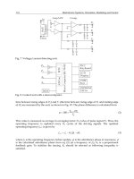
Fig. 3. Equivalent circuit of the piezoelectric transformer.
3.2 Characteristics of the PT
There is no output current in the receiving portion when the electrodes are open-circuited.
Thus, voltage step-up ratio for the PT can be obtained based on Eqs.(35)(37). Substituting I
o
=0 into Eq.(37) and eliminating X(s) from Eqs. (35)(37) gives
22
)()(
)(
oonnn
io
i
o
ACksdsm
AA
sV
sV
.
(44)
When a load resistance R
L
is connected between the electrodes in the receiving portion of the
PT, Eq.(45) can be obtained by substituting I
o
=V
o
/R
L
into Eq.(37).
Loooo
RVVsCXsA /
(45)
The voltage step-up ratio for the PT with a load resistance R
L
in the receiving portion can be
obtained based on Eqs.(35)(45) as the following.
LoLonnn
Loi
i
o
RsARsCksdsm
RAsA
sV
sV
22
)1)(()(
)(
(46)
If the electrodes in the receiving portion of the PT is short-circuited, the voltage step-up ratio
for the PT can be obtained as zero by substituting R
L
=0 into Eq.(46). In addition, Eq.(46)
shows that the higher the load resistance R
L
, the higher the voltage step-up ratio. The
maximum voltage step-up ratio can be obtained as Eq.(44) when the load resistance R
L
approach infinite. On the other hand, the output power of the PT can be calculated by the
power consumption of the load resistance R
L
as the following:
Loo
RVP /
2
(47)
If the natural frequency is chosen as the operating frequency in the PT, then the voltage
step-up ratio can be rewritten as
oLnnon
oi
i
o
ARddCj
AA
V
V
/
(48)
Therefore, the output power of the PT can be obtained by substituting Eq.(48) into Eq.(47).
])/()[(
/
22
222
2
oLnnonL
ioi
Loo
ARddCR
VAA
RVP
(49)
According to equivalent circuit of the PT shown as in Fig.3, the input power of the PT can be
calculated by the sum of the power consumption of the damping d
n
and that of the load
resistance R
L
. Eq.(37) shows that the current flowing through d
n
is (sC
o
V
o
+I
o
)/A
o
, thus the
input power of the PT can be obtained as
oLooon
o
n
i
PRVVCj
A
d
P
2
2
/
]/1)/()/([
222
LoLnoonno
RARdACdV
.
(50)
Therefore, the efficiency of the PT can be obtained as
1)/()/(
1
22
LonoonLni
o
RAdACRdP
P
.
(51)
The maximum efficiency can be calculated by the differential of Eq.(50). Thus, the
maximum efficiency can be obtained when the optimal load resistance R
L,opt
is
)/(1
, onoptL
CR
.
(52)
Substituting Eq.(52) into Eq.(51) gives the maximum efficiency.
2
2
max
2
oonn
o
ACd
A
(53)
It is note that the smaller the damping coefficient d
n
, the higher the maximum efficiency.
4. Simulation and Experiment
4.1 Experimental Setup and the Impedance Measurements
To verify the electromechanical model, a ring-type PT with 16mm in outer diameter, 8mm in
inner diameter, and 1mm in thickness was used. The PT is has silver electrodes on two