Mechatronic Systems, Simulation, Modeling and Control Part 12 doc
Bạn đang xem bản rút gọn của tài liệu. Xem và tải ngay bản đầy đủ của tài liệu tại đây (1.14 MB, 18 trang )
MechatronicSystems,Simulation,ModellingandControl272
The partial model Behavior – Sequence describes the interaction of several system
elements. The activities, being carried out during the interaction of the system ele-
ments, and the inter-changed information, are modeled in a chronological order.
4.2 Interrelations between the partial models
The partial models represent the different aspects of the principle solution of a self-
optimizing system. The interrelations between the partial models which describe the cohe-
rence of the partial models are of high importance. Those interrelations are built up between
the constructs of the relating partial models. There are, for example, functions (construct of
the partial model functions) that are realized by system elements (construct of the partial
model active structure). These system elements perform activities (construct of the partial
model behavior – activities), whereas the activities might result out of the functions of the par-
tial model functions. There could also be the achieving of a certain temperature (construct in-
fluence of the partial model environment) as an event (construct of the partial model behavior –
states) that causes the activation of a new state (construct of the partial model behavior –
states) and other activities. Table 1 shows a couple of interrelations between the partial mod-
els. The interrelations are shown directed to the right, i.e. in the table’s left side there are the
constructs which cause correlation, on the table’s right side there are the constructs affecting
the connections (an example in the 3
rd
line, table 1).
activates
activates
results from
decides
sets boundaries for
results from
has (opt.)
persuades (opt.)
takes
performs
realizes
kind of
interrelation
environment
environment
functions
requirements
requirements
behavior – activities
active structure
active structure
active structure
active structure
active structure
partial model
…
behavior – activitiesactivityinfluence/event
behavior – statestateinfluence/event
requirementsrequirementfunction
functionsfunctionrequirement
shapevolumesrequirement
functionsfunctionactivity
shapevolumessystem element
system of objectivesobjectivesystem element
behavior – statestatesystem element
behavior – activitiesactivitysystem element
functionsfunctionsystem element
partial modelconstructconstruct
activates
activates
results from
decides
sets boundaries for
results from
has (opt.)
persuades (opt.)
takes
performs
realizes
kind of
interrelation
environment
environment
functions
requirements
requirements
behavior – activities
active structure
active structure
active structure
active structure
active structure
partial model
…
behavior – activitiesactivityinfluence/event
behavior – statestateinfluence/event
requirementsrequirementfunction
functionsfunctionrequirement
shapevolumesrequirement
functionsfunctionactivity
shapevolumessystem element
system of objectivesobjectivesystem element
behavior – statestatesystem element
behavior – activitiesactivitysystem element
functionsfunctionsystem element
partial modelconstructconstruct
Table 1. Interrelations between the partial models (cut-out)
A system element within the partial model active structure takes up a state in the partial
model behavior – states. Optional interrelations are marked by (opt.). Taking the information
in table 1 as a basis, a so-called integration model is created, which complements all the al-
ready described partial models.
4.3 Particularities within the specification of self-optimizing systems
Chapter 1 already pointed out that the self-optimizing process initiates a new state of the
system. The system is transformed from one configuration into another. The partial model
behavior – states displays all relevant states of the system. It also contains all the events in-
itiating a state transition. The configuration of a system in a specific state is described by its
active structure. That means, the active structure can be differently shaped in different
states, for example, if different elements of the system (controllers, sensors) are used for the
execution of the self-optimizing process. A system’s behavior in a certain state is described
by its operation process. Operation processes are for example the acquisition of information
about the environment, the derivation of adequate control interactions, and the controlling
itself. State transitions are realized by adaptation processes, i.e. by self-optimizing processes.
The operation and adaptation processes are modeled in the partial model behavior – activities.
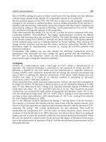
In order to describe the self-optimizing process, all of the three partial models need to be
considered simultaneously (figure 13). Every state of the partial models behavior – states is
assigned to an operation process of the partial model behavior – activities, which is operating
actively in that state. Moreover, every state is related to a configuration of the active struc-
ture, which also actively operates. One example: The state S5, the respective operation
process and the configuration of the active structure are emphasized by light grey colored,
logical groups. The operation process takes place in a periodic way.
active structure
behavior –
activities
SE 1
SE 2
SE 4
SE 3
SE 7
SE 8
SE10
SE 5 SE 6
SE 9
S
O,B
A 10
A 9
A 6
A 1
A 4
A 2
A 7
A 8
A 5
S
A 3
O
B
legend
S
O
B
system element
activity
state
event
analyzing the current situation
determining the systems‘s objectives
adapting the system‘s behavior
logical group
relation
is assigned to
alternative
S1
S2
S3
behavior –
states
S6
S5
S4
E 1
E 5
E 4
E 7
E 6
E 3
E 2
E 8
E
SE
A
S
Fig. 13.Cooperation of the partial models active structure, behavior – states and behavior –
activities in order to describe the self-optimization (simplified visualization of the principle)
ArchitectureandDesignMethodologyofSelf-OptimizingMechatronicSystems 273
The partial model Behavior – Sequence describes the interaction of several system
elements. The activities, being carried out during the interaction of the system ele-
ments, and the inter-changed information, are modeled in a chronological order.
4.2 Interrelations between the partial models
The partial models represent the different aspects of the principle solution of a self-
optimizing system. The interrelations between the partial models which describe the cohe-
rence of the partial models are of high importance. Those interrelations are built up between
the constructs of the relating partial models. There are, for example, functions (construct of
the partial model functions) that are realized by system elements (construct of the partial
model active structure). These system elements perform activities (construct of the partial
model behavior – activities), whereas the activities might result out of the functions of the par-
tial model functions. There could also be the achieving of a certain temperature (construct in-
fluence of the partial model environment) as an event (construct of the partial model behavior –
states) that causes the activation of a new state (construct of the partial model behavior –
states) and other activities. Table 1 shows a couple of interrelations between the partial mod-
els. The interrelations are shown directed to the right, i.e. in the table’s left side there are the
constructs which cause correlation, on the table’s right side there are the constructs affecting
the connections (an example in the 3
rd
line, table 1).
activates
activates
results from
decides
sets boundaries for
results from
has (opt.)
persuades (opt.)
takes
performs
realizes
kind of
interrelation
environment
environment
functions
requirements
requirements
behavior – activities
active structure
active structure
active structure
active structure
active structure
partial model
…
behavior – activitiesactivityinfluence/event
behavior – statestateinfluence/event
requirementsrequirementfunction
functionsfunctionrequirement
shapevolumesrequirement
functionsfunctionactivity
shapevolumessystem element
system of objectivesobjectivesystem element
behavior – statestatesystem element
behavior – activitiesactivitysystem element
functionsfunctionsystem element
partial modelconstructconstruct
activates
activates
results from
decides
sets boundaries for
results from
has (opt.)
persuades (opt.)
takes
performs
realizes
kind of
interrelation
environment
environment
functions
requirements
requirements
behavior – activities
active structure
active structure
active structure
active structure
active structure
partial model
…
behavior – activitiesactivityinfluence/event
behavior – statestateinfluence/event
requirementsrequirementfunction
functionsfunctionrequirement
shapevolumesrequirement
functionsfunctionactivity
shapevolumessystem element
system of objectivesobjectivesystem element
behavior – statestatesystem element
behavior – activitiesactivitysystem element
functionsfunctionsystem element
partial modelconstructconstruct
Table 1. Interrelations between the partial models (cut-out)
A system element within the partial model active structure takes up a state in the partial
model behavior – states. Optional interrelations are marked by (opt.). Taking the information
in table 1 as a basis, a so-called integration model is created, which complements all the al-
ready described partial models.
4.3 Particularities within the specification of self-optimizing systems
Chapter 1 already pointed out that the self-optimizing process initiates a new state of the
system. The system is transformed from one configuration into another. The partial model
behavior – states displays all relevant states of the system. It also contains all the events in-
itiating a state transition. The configuration of a system in a specific state is described by its
active structure. That means, the active structure can be differently shaped in different
states, for example, if different elements of the system (controllers, sensors) are used for the
execution of the self-optimizing process. A system’s behavior in a certain state is described
by its operation process. Operation processes are for example the acquisition of information
about the environment, the derivation of adequate control interactions, and the controlling
itself. State transitions are realized by adaptation processes, i.e. by self-optimizing processes.
The operation and adaptation processes are modeled in the partial model behavior – activities.
In order to describe the self-optimizing process, all of the three partial models need to be
considered simultaneously (figure 13). Every state of the partial models behavior – states is
assigned to an operation process of the partial model behavior – activities, which is operating
actively in that state. Moreover, every state is related to a configuration of the active struc-
ture, which also actively operates. One example: The state S5, the respective operation
process and the configuration of the active structure are emphasized by light grey colored,
logical groups. The operation process takes place in a periodic way.
active structure
behavior –
activities
SE 1
SE 2
SE 4
SE 3
SE 7
SE 8
SE10
SE 5 SE 6
SE 9
S
O,B
A 10
A 9
A 6
A 1
A 4
A 2
A 7
A 8
A 5
S
A 3
O
B
legend
S
O
B
system element
activity
state
event
analyzing the current situation
determining the systems‘s objectives
adapting the system‘s behavior
logical group
relation
is assigned to
alternative
S1
S2
S3
behavior –
states
S6
S5
S4
E 1
E 5
E 4
E 7
E 6
E 3
E 2
E 8
E
SE
A
S
Fig. 13.Cooperation of the partial models active structure, behavior – states and behavior –
activities in order to describe the self-optimization (simplified visualization of the principle)
MechatronicSystems,Simulation,ModellingandControl274
Now – when event E7 appears, an adaptation process is triggered. Therefore, the necessary
system elements are activated. Both, the adaptation process and the configuration of system
elements, are assigned to the event E7 (see medium grey background in figure 13). After
performing the adaptation process, the system takes over the new state S6. A new operation
process and a new configuration of system elements are activated. They are colored in a
dark grey within figure 13. The adaptation process and the used system elements are no
longer activated.
5. Conceptual design of self-optimizing systems
As mentioned in chapter 2, the basic construction and the operation mode of the system are
defined within the conceptual design phase. The basic procedure is divided into four sub-
phases (figure 14), which are explained in detail below. [GFD+08]
Fig. 14. Process of conceptual design of self-optimizing systems
Planning and clarifying the task
This sub-phase identifies the design task and the resulting requirements on the system is
worked out in here (figure 15). At first the task is analyzed in detail. At this the predefined
basic conditions for the product, the product program, and the product development are
taken into account. This is followed by an analysis of the operational environment which in-
vestigates the most important boundary conditions and influences on the system. The exter-
nal objectives emerge next to disturbances. Beyond that, consistent combinations of influ-
ences, so-called situations, are generated. By the combination of characteristic situations
with a first discretion of the system’s behavior, application scenarios occur. By using the
structuring procedure by S
TEFFEN it is possible to identify a development-oriented product
structure for the system and design rules, which guide the developers to realize this product
structure type [Ste07]. The results of this sub-phase are the list of requirements, the envi-
ronment model, the aspired product structure type and the assigned design rules as well as
the application scenarios.
Fig. 15. Conceptual design phase “planning and clarifying the task”
Conceptual design on the system’s level
Based on previously determined requirements of the system, solution variants are devel-
oped for each application scenario (figure 16). The main functions are derived from the re-
quirements and set into a function hierarchy.
solution of application scenario n
solution of application scenario 2
solution of application scenario 1
function
hierarchy
modified
function
hierarchy
active
structure
approach for
solution
S.O potential
S.O concept
selected
solution elements
shape
selected
solution patterns
system
behavior
internal objectives
principle solution
on system’s level
possible solutions
draw up function
hierarchy
modifying the
functionhierarchy
identifying
solution pattern
identifying
solution elements
define
active structure
define
shape
define
behavior
identifying
internal objectives
analysing
and evaluating
creating
S.O concept
identifying
S O. potential
consolidating
of solutions
selecting
specific solution
module n
module 2
module 1
integration of
the concept
conceptual
design on the
module’s level
decomposition
conceptual
design on the
system’s level
planning and
clarifying the task
Fig. 16. Conceptual design phase “conceptual design on system’s level”
ArchitectureandDesignMethodologyofSelf-OptimizingMechatronicSystems 275
Now – when event E7 appears, an adaptation process is triggered. Therefore, the necessary
system elements are activated. Both, the adaptation process and the configuration of system
elements, are assigned to the event E7 (see medium grey background in figure 13). After
performing the adaptation process, the system takes over the new state S6. A new operation
process and a new configuration of system elements are activated. They are colored in a
dark grey within figure 13. The adaptation process and the used system elements are no
longer activated.
5. Conceptual design of self-optimizing systems
As mentioned in chapter 2, the basic construction and the operation mode of the system are
defined within the conceptual design phase. The basic procedure is divided into four sub-
phases (figure 14), which are explained in detail below. [GFD+08]
Fig. 14. Process of conceptual design of self-optimizing systems
Planning and clarifying the task
This sub-phase identifies the design task and the resulting requirements on the system is
worked out in here (figure 15). At first the task is analyzed in detail. At this the predefined
basic conditions for the product, the product program, and the product development are
taken into account. This is followed by an analysis of the operational environment which in-
vestigates the most important boundary conditions and influences on the system. The exter-
nal objectives emerge next to disturbances. Beyond that, consistent combinations of influ-
ences, so-called situations, are generated. By the combination of characteristic situations
with a first discretion of the system’s behavior, application scenarios occur. By using the
structuring procedure by S
TEFFEN it is possible to identify a development-oriented product
structure for the system and design rules, which guide the developers to realize this product
structure type [Ste07]. The results of this sub-phase are the list of requirements, the envi-
ronment model, the aspired product structure type and the assigned design rules as well as
the application scenarios.
Fig. 15. Conceptual design phase “planning and clarifying the task”
Conceptual design on the system’s level
Based on previously determined requirements of the system, solution variants are devel-
oped for each application scenario (figure 16). The main functions are derived from the re-
quirements and set into a function hierarchy.
solution of application scenario n
solution of application scenario 2
solution of application scenario 1
function
hierarchy
modified
function
hierarchy
active
structure
approach for
solution
S.O potential
S.O concept
selected
solution elements
shape
selected
solution patterns
system
behavior
internal objectives
principle solution
on system’s level
possible solutions
draw up function
hierarchy
modifying the
functionhierarchy
identifying
solution pattern
identifying
solution elements
define
active structure
define
shape
define
behavior
identifying
internal objectives
analysing
and evaluating
creating
S.O concept
identifying
S O. potential
consolidating
of solutions
selecting
specific solution
module n
module 2
module 1
integration of
the concept
conceptual
design on the
module’s level
decomposition
conceptual
design on the
system’s level
planning and
clarifying the task
Fig. 16. Conceptual design phase “conceptual design on system’s level”
MechatronicSystems,Simulation,ModellingandControl276
The function hierarchy needs to be modified according to the specific application scenarios,
e.g. irrelevant functions are removed and specific sub-functions are added. Then there is a
search for “solution patterns” in order to realize the documented functions of the function
hierarchy, which will be inserted into a morphologic box.
We use “solution pattern” as a general term. A pattern describes a reoccurring problem and
also the solution’s core of the problem [AIS+77]. Taking this as a starting point, it results in
the classification shown in figure 17. We differentiate between solution patterns that rely on
physical effects and between patterns exclusively serving the data processing. The design
methodology of mechanical engineering describes the first group as active principles; they
describe the principle solution for the realization of a function. The course of development
concretizes active principles to material components and patterns of information processing
to software components. The relations between active principles and components are of the
type n:m; the characteristic depends on the basic method of embodiment design (differential
construction method and integrated construction method). Within the integral construction,
several active patterns are realized by one component; whereas in the differential construc-
tion several components fulfill one active pattern. This is exactly the same in the field of in-
formation processing. Basically, a definite modern mechanical engineering system consists
of a construction structure that means an arrangement of shape-marked components within
a space and their logic aggregation to assemblies and products, and a component structure
that means the compound of software components.
Fig. 17. classification of solution patterns
In some times, there are already existing, well-established solutions which we call “solution
elements”. If there are such solution elements, they will be chosen instead of the abstract so-
lution patterns. The search for solution patterns is supported by a solution pattern cata-
logue. We use the consistency analysis in order to determine useful combinations of solution
patterns of the morphologic box [Köc04]. As a result, there will be consistent bunches of so-
lution patterns, with a solution pattern for each function.
The consistent bunches of solution patterns form the basis for the development of the active
structure. In this step, the refinement of the solution patterns to system elements takes place
as well. System elements form an intermediate step between solution patterns on one side
and shape-marked components or rather software components on the other side. Based on
the active structure, an initial construction structure can be developed because there are
primal details on the shape within the system elements. In addition, the system’s behavior is
roughly modeled in this step. Basically, this concerns the activities, states and state transi-
tions of the system as well as the communication and cooperation with other systems and
subsystems. The analysis of the system’s behavior produces an imagination of the optimiz-
ing processes, running within the system. The external, inherent and internal objectives can
be defined.
The solutions for the application scenarios need to be combined. It is important that worka-
ble configurations are created which make a reconfiguration of the system possible. Keeping
this information in mind, it is identified if there is a containing potential of self-optimization
at all. There is a potential for self-optimization if the changing influences on the system re-
quire modifications of the pursued objectives and the system needs to adjust its behavior. If
there is potential for self-optimization, the function hierarchy needs to be complemented by
self-optimizing functions. In particular solution patterns of self-optimization are applied to
enable self-optimizing behavior. The resulting changes and extensions of system structure
and system behavior need to be included appropriately.
The best solution for each application scenario is chosen and these solutions are consoli-
dated to a principle solution on the system’s level. Afterwards, an analysis takes place
which looks for contradictions within the principle solution of the system and which con-
tradictions might be solved by self-optimization. Self-optimizing concepts for such contra-
dictions are defined, which contain the three basic steps of self-optimization. The principle
solution of a self-optimizing system on the system’s level is the result of this phase.
Conceptual design on the module’s level
The principle solution on the system’s level describes the whole system. It is necessary to
have a closer look at the solution, in order to give a statement on the technical and economi-
cal realization of the principle solution. For that purpose, the system is decomposed into
modules by using the already mentioned structuring procedure by S
TEFFEN. The decomposi-
tion is based on the aspired product structure [Ste07], [GSD+09]. Afterwards a principle so-
lution for each single module is developed. The development of a principle solution for each
single module corresponds to the “conceptual design on the system’s level”, starting out
with “planning and clarifying the task”. This phase results in principle solutions on the
module’s level.
ArchitectureandDesignMethodologyofSelf-OptimizingMechatronicSystems 277
The function hierarchy needs to be modified according to the specific application scenarios,
e.g. irrelevant functions are removed and specific sub-functions are added. Then there is a
search for “solution patterns” in order to realize the documented functions of the function
hierarchy, which will be inserted into a morphologic box.
We use “solution pattern” as a general term. A pattern describes a reoccurring problem and
also the solution’s core of the problem [AIS+77]. Taking this as a starting point, it results in
the classification shown in figure 17. We differentiate between solution patterns that rely on
physical effects and between patterns exclusively serving the data processing. The design
methodology of mechanical engineering describes the first group as active principles; they
describe the principle solution for the realization of a function. The course of development
concretizes active principles to material components and patterns of information processing
to software components. The relations between active principles and components are of the
type n:m; the characteristic depends on the basic method of embodiment design (differential
construction method and integrated construction method). Within the integral construction,
several active patterns are realized by one component; whereas in the differential construc-
tion several components fulfill one active pattern. This is exactly the same in the field of in-
formation processing. Basically, a definite modern mechanical engineering system consists
of a construction structure that means an arrangement of shape-marked components within
a space and their logic aggregation to assemblies and products, and a component structure
that means the compound of software components.
Fig. 17. classification of solution patterns
In some times, there are already existing, well-established solutions which we call “solution
elements”. If there are such solution elements, they will be chosen instead of the abstract so-
lution patterns. The search for solution patterns is supported by a solution pattern cata-
logue. We use the consistency analysis in order to determine useful combinations of solution
patterns of the morphologic box [Köc04]. As a result, there will be consistent bunches of so-
lution patterns, with a solution pattern for each function.
The consistent bunches of solution patterns form the basis for the development of the active
structure. In this step, the refinement of the solution patterns to system elements takes place
as well. System elements form an intermediate step between solution patterns on one side
and shape-marked components or rather software components on the other side. Based on
the active structure, an initial construction structure can be developed because there are
primal details on the shape within the system elements. In addition, the system’s behavior is
roughly modeled in this step. Basically, this concerns the activities, states and state transi-
tions of the system as well as the communication and cooperation with other systems and
subsystems. The analysis of the system’s behavior produces an imagination of the optimiz-
ing processes, running within the system. The external, inherent and internal objectives can
be defined.
The solutions for the application scenarios need to be combined. It is important that worka-
ble configurations are created which make a reconfiguration of the system possible. Keeping
this information in mind, it is identified if there is a containing potential of self-optimization
at all. There is a potential for self-optimization if the changing influences on the system re-
quire modifications of the pursued objectives and the system needs to adjust its behavior. If
there is potential for self-optimization, the function hierarchy needs to be complemented by
self-optimizing functions. In particular solution patterns of self-optimization are applied to
enable self-optimizing behavior. The resulting changes and extensions of system structure
and system behavior need to be included appropriately.
The best solution for each application scenario is chosen and these solutions are consoli-
dated to a principle solution on the system’s level. Afterwards, an analysis takes place
which looks for contradictions within the principle solution of the system and which con-
tradictions might be solved by self-optimization. Self-optimizing concepts for such contra-
dictions are defined, which contain the three basic steps of self-optimization. The principle
solution of a self-optimizing system on the system’s level is the result of this phase.
Conceptual design on the module’s level
The principle solution on the system’s level describes the whole system. It is necessary to
have a closer look at the solution, in order to give a statement on the technical and economi-
cal realization of the principle solution. For that purpose, the system is decomposed into
modules by using the already mentioned structuring procedure by S
TEFFEN. The decomposi-
tion is based on the aspired product structure [Ste07], [GSD+09]. Afterwards a principle so-
lution for each single module is developed. The development of a principle solution for each
single module corresponds to the “conceptual design on the system’s level”, starting out
with “planning and clarifying the task”. This phase results in principle solutions on the
module’s level.
MechatronicSystems,Simulation,ModellingandControl278
Integration of the concept
The module’s principle solutions will be integrated into a detailed principle solution of the
whole system. Again there is an analysis in order to find contradictions within the principle
solutions of the modules and it is checked if these contradictions can be solved by self-
optimization. Concluding, a technical-economical evaluation of the solution takes place. The
result of this phase is a principle solution of the whole system that serves as a starting point
for the subsequent concretization.
Integration of the concept: The module’s principle solutions will be integrated into a de-
tailed principle solution of the whole system. There is an analysis in order to find contradic-
tions within the principle solutions of the modules. Again it will be checked if these contra-
dictions can be solved by self-optimization. Concluding, a technical-economical evaluation
of the solution is taking place. The result of that phase is a principle solution of the whole
system that serves as a starting point for the subsequent concretization. This concretization
is carried out parallel in the specific domains (mechanical engineering, electrical engineer-
ing, control engineering and software engineering). Chapter 7 gives further information on
this.
On the basis of an example, the phases planning and clarifying the task as well as conceptual de-
sign on the system’s level will be described into detail. There will not be any further considera-
tion of the conceptual design on the module’s level because it operates by analogy with the con-
ceptual design on the system’s level. The integration of the concept has also been explained and is
not being discussed anymore.
6. The role of the principle solution during the concretization
The communication and cooperation of the developers from the different domains through-
out the whole development process is very important for a successful and efficient devel-
opment of self-optimizing systems. The principle solution forms the basis for this communi-
cation and cooperation.
Within the conceptual design phase the domain-spanning development tasks are carried out
in a cooperative way. Within the concretization the developers work on different modules
and in different domains. Thus their specific development tasks in one domain of a module
need to be synchronized with those of other domains respectively other modules. The de-
velopment processes for the modules are synchronized by one superior process of the total
system (figure 18). Within this process comprehensive aspects of the system like the shell or
the dynamics of the whole system are developed in detail. [GRD+09]
principle solution
complete
systemdesign
concretization
mechanics
software engineering
control engineering
electric/electronics
conceptual
design
module n
mechanics
software engineering
control engineering
electric/electronics
module 1
synchronization
Legend
total system
Fig. 18. Basic structure of the development process [GRD+09]
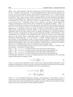
Furthermore, the information, based in the principle solution, serves as a fundament for de-
ducing of domain-specific concretization tasks. In a first step, the system elements of a do-
main and their relations within the active structure will be identified. After that will be ana-
lyzed what kind of domain-specific functions are fulfilled by the system elements, which
requirements they have to comply and which behavior is appropriate in certain situations.
Following this, it will be checked if domain-specific requirements need to be added. In case
of a software engineering, the necessary software components of the component structure,
including the input- and output parameters, can be deduced by the system elements of the
active structure (figure 18) [GSD+09].
RailCab
Configuration
Control
Hazard
Detection
d*
convoy
state
detected
hazards
x
leader
, v
leader
x
RailCab
, v
RailCab
Distance
Sensor
d
Safe
Velocity
Control
Operating
Point
Controller
F*
SE
SE
SE
SE
RailCab
Configuration
Control
Velocity
Control
Hazard
Detection
Configuration
Control
RailCabTo
RailCab
Communication
Module
x
RailCab
,
v
RailCab
x
RailCab
,
v
RailCab
F*
d*
convoy
state
x
leader
,
v
leader
detected
Hazards
d
Safe
DistanceSensor
x
RailCab
,
v
RailCab
SE
x
leader
,v
leader
x
RailCab
,v
RailCab
distance to
object
distance to
object
1
initial
transformation
2
adding the
distance
sensor
3
updating the
principle solution
Fig. 19. The transformation from the active structure into a component diagram (software
engineering) [GSD+09]
In case of changes occur during the domain-specific concretization, which affect other do-
mains have to be transferred back into the principle solution. This happens for example if
ArchitectureandDesignMethodologyofSelf-OptimizingMechatronicSystems 279
Integration of the concept
The module’s principle solutions will be integrated into a detailed principle solution of the
whole system. Again there is an analysis in order to find contradictions within the principle
solutions of the modules and it is checked if these contradictions can be solved by self-
optimization. Concluding, a technical-economical evaluation of the solution takes place. The
result of this phase is a principle solution of the whole system that serves as a starting point
for the subsequent concretization.
Integration of the concept: The module’s principle solutions will be integrated into a de-
tailed principle solution of the whole system. There is an analysis in order to find contradic-
tions within the principle solutions of the modules. Again it will be checked if these contra-
dictions can be solved by self-optimization. Concluding, a technical-economical evaluation
of the solution is taking place. The result of that phase is a principle solution of the whole
system that serves as a starting point for the subsequent concretization. This concretization
is carried out parallel in the specific domains (mechanical engineering, electrical engineer-
ing, control engineering and software engineering). Chapter 7 gives further information on
this.
On the basis of an example, the phases planning and clarifying the task as well as conceptual de-
sign on the system’s level will be described into detail. There will not be any further considera-
tion of the conceptual design on the module’s level because it operates by analogy with the con-
ceptual design on the system’s level. The integration of the concept has also been explained and is
not being discussed anymore.
6. The role of the principle solution during the concretization
The communication and cooperation of the developers from the different domains through-
out the whole development process is very important for a successful and efficient devel-
opment of self-optimizing systems. The principle solution forms the basis for this communi-
cation and cooperation.
Within the conceptual design phase the domain-spanning development tasks are carried out
in a cooperative way. Within the concretization the developers work on different modules
and in different domains. Thus their specific development tasks in one domain of a module
need to be synchronized with those of other domains respectively other modules. The de-
velopment processes for the modules are synchronized by one superior process of the total
system (figure 18). Within this process comprehensive aspects of the system like the shell or
the dynamics of the whole system are developed in detail. [GRD+09]
principle solution
complete
systemdesign
concretization
mechanics
software engineering
control engineering
electric/electronics
conceptual
design
module n
mechanics
software engineering
control engineering
electric/electronics
module 1
synchronization
Legend
total system
Fig. 18. Basic structure of the development process [GRD+09]
Furthermore, the information, based in the principle solution, serves as a fundament for de-
ducing of domain-specific concretization tasks. In a first step, the system elements of a do-
main and their relations within the active structure will be identified. After that will be ana-
lyzed what kind of domain-specific functions are fulfilled by the system elements, which
requirements they have to comply and which behavior is appropriate in certain situations.
Following this, it will be checked if domain-specific requirements need to be added. In case
of a software engineering, the necessary software components of the component structure,
including the input- and output parameters, can be deduced by the system elements of the
active structure (figure 18) [GSD+09].
RailCab
Configuration
Control
Hazard
Detection
d*
convoy
state
detected
hazards
x
leader
, v
leader
x
RailCab
, v
RailCab
Distance
Sensor
d
Safe
Velocity
Control
Operating
Point
Controller
F*
SE
SE
SE
SE
RailCab
Configuration
Control
Velocity
Control
Hazard
Detection
Configuration
Control
RailCabTo
RailCab
Communication
Module
x
RailCab
,
v
RailCab
x
RailCab
,
v
RailCab
F*
d*
convoy
state
x
leader
,
v
leader
detected
Hazards
d
Safe
DistanceSensor
x
RailCab
,
v
RailCab
SE
x
leader
,v
leader
x
RailCab
,v
RailCab
distance to
object
distance to
object
1
initial
transformation
2
adding the
distance
sensor
3
updating the
principle solution
Fig. 19. The transformation from the active structure into a component diagram (software
engineering) [GSD+09]
In case of changes occur during the domain-specific concretization, which affect other do-
mains have to be transferred back into the principle solution. This happens for example if
MechatronicSystems,Simulation,ModellingandControl280
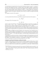
there will be identified additional internal objectives during the course of concretization of a
self-optimization process (in the frame of the determination of objectives). Thus the prin-
ciple solution becomes a domain-spanning system model for the concretization. The aim is
to keep this domain-spanning system model and the domain-specific models consistently.
Figure 20 schematically shows the versions of the domain-spanning system specification
and the different domain-specific models that are created in the course of the concretization.
The shown change scenario can be realized by the use of automated model transformations
[GSD+09].
v1.0
ME
v1.1
ME
v1.2
ME
v1.1
CE
v1.2
CE
v1.0
EE
v1.1
EE
v1.2
EE
v1.0
SE
v1.1
SE
v1.2
SE
v0.2
v0.3
v1.0
v0.1
System Integration
v1.1
v1.2
Concretization Conceptual DesignTransition
v1.0
CE
Initial transformation and mapping
of corresponding design artifacts
Domain-spanning relevant change
(Insertion of a distance sensor component)
Update of the system specification
through existing correspondences
Update of domain-specific models
through existing correspondences
Domain-spanning relevant change
(Refinement of distance sensor to laser unit)
Update of the system specification
through existing correspondences
Update of domain-specific models
through existing correspondences
1
2
3
4
5
6
7
v1.1
SE
v1.1
CE
v1.1
EE
v1.1
ME
Software Engineering Models
Control Engineering Models
Electrical Engineering Models
Mechanical Eng. Models
v1.1
Domain-Spanning Models
Fig. 20. Propagation of relevant changes between the domain-specific models and the do-
main-spanning system specification [GSD+09]
7. Conclusion
The paradigm of self-optimization will enable fascinating perspectives for the future devel-
opment of mechanical engineering systems. These systems rely on the close interaction of
mechanics, electrical engineering/electronics, control engineering and software engineering,
which is aptly expressed by the term mechatronics. At present there is no established meth-
odology for the conceptual design of mechatronic systems, let alone for self-optimizing sys-
tems. Concerning the conceptual design of such systems, the main challenge consists in the
specification of a domain-spanning principle solution, which describes the basic construc-
tion as well as the mode of operation in a domain-spanning way. The presented specifica-
tion technique offers the possibility to create a principle solution for advanced mechatronic
systems, with regard to self-optimizing aspects, such as “application scenarios” and “system
of objectives”. Simultaneously it outperforms classic specification techniques by appropri-
ately encouraging the conceptual design process. It is fundamental to the communication
and cooperation of the participating specialists and enables them to avoid design mistakes,
which base on misunderstandings between them. It has been described in what way the ac-
cording concretization, which takes place parallel to the participating domains, is going to
be structured and coordinated on the basis of the principle solution. The practicability of the
specification technique and the appropriate methodology was demonstrated by the example
of a complex railway vehicle.
8. Acknowledgement
This contribution was developed and published in the course of the Collaborative Research
Center 614 “Self-Optimizing Concepts and Structures in Mechanical Engineering” funded
by the German Research Foundation (DFG) under grant number SFB 614.
9. References
[ADG+08] ADELT, P.; DONOTH, J.; GAUSEMEIER, J.; GEISLER, J.; HENKLER, S.; KAHL,
S.; KLÖPPER, B.; KRUPP, A.; MÜNCH, E.; OBERTHÜR, S.; PAIZ, C.; PODLOGAR,
H.; PORRMANN, M.; RADKOWSKI, R.; ROMAUS, C.; SCHMIDT, A.; SCHULZ,
B.; VÖCKING, H.; WITKOWSKI, U.; WITTING, K.; ZNAMENSHCHYKOV, O.:
Selbstoptimierende Systeme des Maschinenbaus – Definitionen, Anwendungen,
Konzepte. HNI-Verlagsschriftenreihe, Band 234, Paderborn, 2008
[AIS+77] Alexander, C.; Ishikawa, S.; Silverstein, M.; Jacobson, M.; Fiksdahl-King, I.; Angel,
A.: A Pattern Language. Oxford University Press, New York, 1977
[Bir80]Birkhofer, H.: Analyse und Synthese der Funktionen technischer Produkte. Disserta-
tion, Technische Universität Braunschweig, 1980
[Ehr03]Ehrlenspiel, K.: Integrierte Produktentwicklung. Carl Hanser Verlag, München, 2003
[GEK01]Gausemeier, J.; Ebbesmeyer, P.; Kallmeyer, F.: Produktinnovation - Strategische
Planung und Entwicklung der Produkte von morgen. Carl Hanser Verlag, Mün-
chen, 2001
[GFD+08]Gausemeier J., Frank U., Donoth J. and Kahl S. Spezifikationstechnik zur Beschrei-
bung der Prinziplösung selbstoptimierender Systeme des Maschinenbaus – Teil
1/2. Konstruktion, Vol. 7/8 and 9, July/August and September 2008, pp. 59-66/
pp. 91-108 (Springer-VDI-Verlag, Düsseldorf).
[GRD+09]Geiger, C.; Reckter, H.; Dumitrescu, R.; Kahl, S.; Berssenbrügge, J.: A Zoomable
User Interface for Presenting Hierarchical Diagrams on Large Screens. In: 13th In-
ternational Conference on Human-Computer Interaction (HCI International 2009),
July 19-24, 2009, San Diego, CA, USA, 2009
[GSD+09]Gausemeier, J.; Steffen, D.; Donoth, J.; Kahl, S.: Conceptual Design of Modularized
Advanced Mechatronic Systems. In: 17th International Conference on Engineering
Design (ICED`09), August 24-27, 2009, Stanford, CA, USA, 2009
[GSG+09]Gausemeier, J.; Schäfer, W.; Greenyer, J.; Kahl, S.; Pook, S.; Rieke, J.: Management
of Cross-Domain Model Consistency during the Development of Advanced Mecha-
tronic Systems. In: 17th International Conference on Engineering Design (ICED`09),
August 24-27, 2009, Stanford, CA, USA, 2009
ArchitectureandDesignMethodologyofSelf-OptimizingMechatronicSystems 281
there will be identified additional internal objectives during the course of concretization of a
self-optimization process (in the frame of the determination of objectives). Thus the prin-
ciple solution becomes a domain-spanning system model for the concretization. The aim is
to keep this domain-spanning system model and the domain-specific models consistently.
Figure 20 schematically shows the versions of the domain-spanning system specification
and the different domain-specific models that are created in the course of the concretization.
The shown change scenario can be realized by the use of automated model transformations
[GSD+09].
v1.0
ME
v1.1
ME
v1.2
ME
v1.1
CE
v1.2
CE
v1.0
EE
v1.1
EE
v1.2
EE
v1.0
SE
v1.1
SE
v1.2
SE
v0.2
v0.3
v1.0
v0.1
System Integration
v1.1
v1.2
Concretization Conceptual DesignTransition
v1.0
CE
Initial transformation and mapping
of corresponding design artifacts
Domain-spanning relevant change
(Insertion of a distance sensor component)
Update of the system specification
through existing correspondences
Update of domain-specific models
through existing correspondences
Domain-spanning relevant change
(Refinement of distance sensor to laser unit)
Update of the system specification
through existing correspondences
Update of domain-specific models
through existing correspondences
1
2
3
4
5
6
7
v1.1
SE
v1.1
CE
v1.1
EE
v1.1
ME
Software Engineering Models
Control Engineering Models
Electrical Engineering Models
Mechanical Eng. Models
v1.1
Domain-Spanning Models
Fig. 20. Propagation of relevant changes between the domain-specific models and the do-
main-spanning system specification [GSD+09]
7. Conclusion
The paradigm of self-optimization will enable fascinating perspectives for the future devel-
opment of mechanical engineering systems. These systems rely on the close interaction of
mechanics, electrical engineering/electronics, control engineering and software engineering,
which is aptly expressed by the term mechatronics. At present there is no established meth-
odology for the conceptual design of mechatronic systems, let alone for self-optimizing sys-
tems. Concerning the conceptual design of such systems, the main challenge consists in the
specification of a domain-spanning principle solution, which describes the basic construc-
tion as well as the mode of operation in a domain-spanning way. The presented specifica-
tion technique offers the possibility to create a principle solution for advanced mechatronic
systems, with regard to self-optimizing aspects, such as “application scenarios” and “system
of objectives”. Simultaneously it outperforms classic specification techniques by appropri-
ately encouraging the conceptual design process. It is fundamental to the communication
and cooperation of the participating specialists and enables them to avoid design mistakes,
which base on misunderstandings between them. It has been described in what way the ac-
cording concretization, which takes place parallel to the participating domains, is going to
be structured and coordinated on the basis of the principle solution. The practicability of the
specification technique and the appropriate methodology was demonstrated by the example
of a complex railway vehicle.
8. Acknowledgement
This contribution was developed and published in the course of the Collaborative Research
Center 614 “Self-Optimizing Concepts and Structures in Mechanical Engineering” funded
by the German Research Foundation (DFG) under grant number SFB 614.
9. References
[ADG+08] ADELT, P.; DONOTH, J.; GAUSEMEIER, J.; GEISLER, J.; HENKLER, S.; KAHL,
S.; KLÖPPER, B.; KRUPP, A.; MÜNCH, E.; OBERTHÜR, S.; PAIZ, C.; PODLOGAR,
H.; PORRMANN, M.; RADKOWSKI, R.; ROMAUS, C.; SCHMIDT, A.; SCHULZ,
B.; VÖCKING, H.; WITKOWSKI, U.; WITTING, K.; ZNAMENSHCHYKOV, O.:
Selbstoptimierende Systeme des Maschinenbaus – Definitionen, Anwendungen,
Konzepte. HNI-Verlagsschriftenreihe, Band 234, Paderborn, 2008
[AIS+77] Alexander, C.; Ishikawa, S.; Silverstein, M.; Jacobson, M.; Fiksdahl-King, I.; Angel,
A.: A Pattern Language. Oxford University Press, New York, 1977
[Bir80]Birkhofer, H.: Analyse und Synthese der Funktionen technischer Produkte. Disserta-
tion, Technische Universität Braunschweig, 1980
[Ehr03]Ehrlenspiel, K.: Integrierte Produktentwicklung. Carl Hanser Verlag, München, 2003
[GEK01]Gausemeier, J.; Ebbesmeyer, P.; Kallmeyer, F.: Produktinnovation - Strategische
Planung und Entwicklung der Produkte von morgen. Carl Hanser Verlag, Mün-
chen, 2001
[GFD+08]Gausemeier J., Frank U., Donoth J. and Kahl S. Spezifikationstechnik zur Beschrei-
bung der Prinziplösung selbstoptimierender Systeme des Maschinenbaus – Teil
1/2. Konstruktion, Vol. 7/8 and 9, July/August and September 2008, pp. 59-66/
pp. 91-108 (Springer-VDI-Verlag, Düsseldorf).
[GRD+09]Geiger, C.; Reckter, H.; Dumitrescu, R.; Kahl, S.; Berssenbrügge, J.: A Zoomable
User Interface for Presenting Hierarchical Diagrams on Large Screens. In: 13th In-
ternational Conference on Human-Computer Interaction (HCI International 2009),
July 19-24, 2009, San Diego, CA, USA, 2009
[GSD+09]Gausemeier, J.; Steffen, D.; Donoth, J.; Kahl, S.: Conceptual Design of Modularized
Advanced Mechatronic Systems. In: 17th International Conference on Engineering
Design (ICED`09), August 24-27, 2009, Stanford, CA, USA, 2009
[GSG+09]Gausemeier, J.; Schäfer, W.; Greenyer, J.; Kahl, S.; Pook, S.; Rieke, J.: Management
of Cross-Domain Model Consistency during the Development of Advanced Mecha-
tronic Systems. In: 17th International Conference on Engineering Design (ICED`09),
August 24-27, 2009, Stanford, CA, USA, 2009
MechatronicSystems,Simulation,ModellingandControl282
[Köc04] Köckerling, M.: Methodische Entwicklung und Optimierung der Wirkstruktur me-
chatronischer Systeme. Dissertation, Fakultät für Maschinenbau, Universität Pa-
derborn, HNI-Verlagsschriftenreihe Band 143, Paderborn, 2004
[Lan00] Langlotz, G.: Ein Beitrag zur Funktionsstrukturentwicklung innovativer Produkte.
Dissertation, Institut für Rechneranwendung in Planung und Konstruktion, Un-
iversität Karlsruhe, Shaker-Verlag, Band 2/2000, Aachen, 2000
[LHL01] Lückel, J.; Hestermeyer, T.; Liu-Henke, X.: Generalization of the Cascade Principle
in View of a Structured Form of Mechatronic Systems. 2001 IEEE/ASME Interna-
tional Conference on Advanced Intelligent Mechatronics (AIM 2001), Villa Olmo;
Como, Italy
[PBF+07]Pahl, G., Beitz, W., Feldhusen, J., Grote, K H.: Engineering Design – A Systematic
Approach. ed. 3, 2007, Springer Verlag, London, 2007
[Rot00]Roth, K H.: Konstruieren mit Konstruktionskatalogen. Springer-Verlag, , Band 1
Konstruktionslehre, 3. Auflage, Berlin, 2000
[Ste07]Steffen, D.: Ein Verfahren zur Produktstrukturierung für fortgeschrittene mechatro-
nische Systeme. Dissertation, Fakultät für Maschinenbau, Universität Paderborn,
HNI-Verlagsschriftenreihe, Paderborn, Band 207, 2007
[VDI04]Verein Deutscher Ingenieure (VDI): VDI-Richtlinie 2206 - Entwicklungsmethodik für
mechatronische Systeme. Beuth-Verlag, Berlin, 2004
[ZBS+05] Zimmer, D.; Böcker, J.; Schmidt, A.; Schulz, B.: Elektromagnetische Direktantriebe
im Vergleich. In: Antriebstechnik, no. 2/2005, Vereinigte Fachverlage GmbH,
Mainz, 2005
[ZS05]Zimmer, D.; Schmidt, A.: Der Luftspalt bei Linearmotor-getriebenen Schienenfahr-
zeugen. In: Antriebstechnik, no. 2/2005, Vereinigte Fachverlage GmbH, Mainz,
2005
ContributionstotheMultifunctionalIntegrationforMicromechatronicSystems 283
Contributions to the Multifunctional Integration for Micromechatronic
Systems
M.GrossardMathieuandM.ChailletNicolas
x
Contributions to the Multifunctional
Integration for Micromechatronic Systems
M. Grossard Mathieu and M. Chaillet Nicolas
CEA, LIST, Service Robotique Interactive, 18 route du Panorama, BP6, FONTENAY
AUX ROSES, F- 92265
France
FEMTO-ST Institute, Automatic Control and Micro-Mechatronic Systems Department
France
1. Introduction
Mechatronics is the interdisciplinary area related to the integration of mechanical, electronic
and control engineering, as well as information technology to design the best solution to a
given technological problem. It implies that mechatronics relates to the design of systems,
devices and products aimed at achieving an optimal balance between basic mechanics and
its overall control. Robotic systems design has certainly been the pioneer field of
mechatronic applications.
Due to the increase in the difficulty to miniaturize these advanced (or intelligent)
technological products, research in the microrobotic field is required to find novel solutions
to design micromechatronic systems. When applying scale reduction to robotic systems
usually encountered at the macroscopic scale, the miniaturization step necessarily implies
functional integration of these systems. This general trend makes microsystems more and
more functionally integrated, which makes them converging towards the adaptronic (or
smart structures) concept.
In this coming mechatronic concept, all functional elements of a conventional closed-loop
system are existent and at least one element is applied in a multifunctional way. The aim of
such a system is to combine the greatest possible number of application-specific function in
one single element. It aims at building up a microstructure that is marked by minor
complexity and high functional density (Fig. 1).
The key idea followed in the micromechatronic design is that three of the four components
(i.e. sensors, actuators and mechanical structure) in smart microrobotic structures are made
of a single functional (or active) material, such as piezoelectric or shape memory alloys
materials. They can perform actuation or/and sensing functions by interchanging energy
forms (for example, electric energy, magnetic energy and mechanical energy).
15
MechatronicSystems,Simulation,ModellingandControl284
Fig. 1. Integrated smart structure (Hurlebaus, 2005).
Most often, these integrated microdevices are compliant mechanisms, i.e. single-bodies,
elastic continua flexible structures that transmit a motion by undergoing elastic
deformation, as opposed to jointed rigid body motions of conventional articulated
mechanisms. Using compliant mechanisms for the design of small scale systems is of a great
interest, because of simplified manufacturing, reduced assembly costs, reduced kinematic
noise, no wear, no backlash, and ability to accommodate unconventional actuation schemes
when they integrate active materials.
These micromechatronic devices consist of a dynamic system combining a flexible
mechanical structure with integrated multifunctional materials. For the simulation and
optimization of such microsystems, control and system theory together with proper
modeling of the plant are to be applied. The finite element method is a widespread tool for
numerical simulation and structural modeling that can include multiphysics due to the cross
coupling effects of the active material. Afterwards, the efficiency and proper positioning of
actuators and sensors in these systems can be analyzed using the concepts of controllability
and observability. Then, the state-space representation is desirable to achieve model
reduction and to perform control design methodologies.
A general overview of design specificities including mechanical and control considerations
for micromechatronic structure is firstly presented in this chapter. Performance criteria
including mechanical performances, spillover treatment, model reduction techniques and
robust control are briefly presented afterwards.
Finally, an example of a new optimal synthesis method to design topology and associated
robust control methodologies for monolithic compliant microstructures is presented. The
method is based on the optimal arrangement of flexible building blocks thanks to a multi-
criteria genetic algorithm. It exploits the piezoelectric effect, thus making realistic the
adaptronic concept, i.e. integration of the actuation/sensing principle inside the mechanical
structure.
2. Design and control specificities of active flexible micromechatronic
systems
In the section, a particular attention is drawn on the approach used for modelling and
optimizing these micromechanisms design.
2.1 Design and modelling
When compared to macroscale mechatronic systems, design of micromechatronic systems
needs some particular attention. Indeed, this miniaturization step implies to rethink the
main functionalities of the traditional systems in accordance to the specificities of the
microscale:
their microstrucure, as well as their fabrication and microassembly process ;
in many applications including Micro Electro Mechanical Systems (MEMS) (Lee 2003),
(Chang 2006), (Kota 1994), surgical tools (Frecker 2005) (Houston 2007), etc, compliant
mechanisms have already been used. They are single-body, elastic continua flexible
structures, that deliver the desired motion by undergoing elastic deformation, as
opposed to jointed rigid body motions of conventional mechanisms. There are many
advantages of compliant mechanisms, among them: simplified manufacturing, reduced
assembly costs, reduced kinematic noise, no wear, no backlash, high precision, and
ability to accommodate unconventional actuation schemes.
their actuators and sensors with high resolution and small size ;
new ways for producing actuation and sensing need to be studied in their physical
principle, as well as their good adaptability for the achieving tasks at the microscale in
term of displacement, force, controllability, observability, etc. The use of active
functional material (also called multifunctional materials), which can convert energy
from one form to the other, are thus widespread in the context of micro-actuator/sensor
design.
their control methodology and implementation.
The design of controllers for active flexible micromechanisms is a challenging problem
because of nonlinearities in the structural system and actuators/sensors behavior,
nonavailability of accurate mathematical models, a large number of resonant modes to
accurately identify and control. Thus, robust control design methods need to be used.
Most often, modelling and simulating active flexible mechanisms can be made following
several steps sketched on Fig. 2. Starting from the chosen active material (such as
piezoelectric ceramics or magnetostrictive materials), coupled with some specific boundary
conditions and system geometry inherent to the problem, the global equations for the
system behavior are established using the equations of dynamic equilibrium and kinematics.
Then, the finite element (FE) method is generally used for discretizing the spatial
distribution of displacements within the flexible structure: it reduces the problem
formulation to a discrete set of differential equations. In this manner, multiphysics problem
can be treated when considering the electromechanical (in the case of piezoelectric
materials) or magnetomechanical (in the case of magnetostrictive materials) couplings of the
active materials. In the perspective of controlling these mechanisms, this dynamic
input/output model is expressed using state-space formalism. Structural models obtained
by using FE method exhibit a huge number of degrees of freedom. Thus, the resulting full
order model has to be drastically reduced thanks to reduction techniques. Usual techniques
of reduction consist in selecting the most influent modes that lie in the frequency spectrum
of interest, i.e. those that are strongly controllable and observable with the actuator/sensor
configuration.
Some examples of software tools related to the simulation (and, in some restrictive case, the
optimization process as well) of smart structures can be found in (Janocha 2007).
ContributionstotheMultifunctionalIntegrationforMicromechatronicSystems 285
Fig. 1. Integrated smart structure (Hurlebaus, 2005).
Most often, these integrated microdevices are compliant mechanisms, i.e. single-bodies,
elastic continua flexible structures that transmit a motion by undergoing elastic
deformation, as opposed to jointed rigid body motions of conventional articulated
mechanisms. Using compliant mechanisms for the design of small scale systems is of a great
interest, because of simplified manufacturing, reduced assembly costs, reduced kinematic
noise, no wear, no backlash, and ability to accommodate unconventional actuation schemes
when they integrate active materials.
These micromechatronic devices consist of a dynamic system combining a flexible
mechanical structure with integrated multifunctional materials. For the simulation and
optimization of such microsystems, control and system theory together with proper
modeling of the plant are to be applied. The finite element method is a widespread tool for
numerical simulation and structural modeling that can include multiphysics due to the cross
coupling effects of the active material. Afterwards, the efficiency and proper positioning of
actuators and sensors in these systems can be analyzed using the concepts of controllability
and observability. Then, the state-space representation is desirable to achieve model
reduction and to perform control design methodologies.
A general overview of design specificities including mechanical and control considerations
for micromechatronic structure is firstly presented in this chapter. Performance criteria
including mechanical performances, spillover treatment, model reduction techniques and
robust control are briefly presented afterwards.
Finally, an example of a new optimal synthesis method to design topology and associated
robust control methodologies for monolithic compliant microstructures is presented. The
method is based on the optimal arrangement of flexible building blocks thanks to a multi-
criteria genetic algorithm. It exploits the piezoelectric effect, thus making realistic the
adaptronic concept, i.e. integration of the actuation/sensing principle inside the mechanical
structure.
2. Design and control specificities of active flexible micromechatronic
systems
In the section, a particular attention is drawn on the approach used for modelling and
optimizing these micromechanisms design.
2.1 Design and modelling
When compared to macroscale mechatronic systems, design of micromechatronic systems
needs some particular attention. Indeed, this miniaturization step implies to rethink the
main functionalities of the traditional systems in accordance to the specificities of the
microscale:
their microstrucure, as well as their fabrication and microassembly process ;
in many applications including Micro Electro Mechanical Systems (MEMS) (Lee 2003),
(Chang 2006), (Kota 1994), surgical tools (Frecker 2005) (Houston 2007), etc, compliant
mechanisms have already been used. They are single-body, elastic continua flexible
structures, that deliver the desired motion by undergoing elastic deformation, as
opposed to jointed rigid body motions of conventional mechanisms. There are many
advantages of compliant mechanisms, among them: simplified manufacturing, reduced
assembly costs, reduced kinematic noise, no wear, no backlash, high precision, and
ability to accommodate unconventional actuation schemes.
their actuators and sensors with high resolution and small size ;
new ways for producing actuation and sensing need to be studied in their physical
principle, as well as their good adaptability for the achieving tasks at the microscale in
term of displacement, force, controllability, observability, etc. The use of active
functional material (also called multifunctional materials), which can convert energy
from one form to the other, are thus widespread in the context of micro-actuator/sensor
design.
their control methodology and implementation.
The design of controllers for active flexible micromechanisms is a challenging problem
because of nonlinearities in the structural system and actuators/sensors behavior,
nonavailability of accurate mathematical models, a large number of resonant modes to
accurately identify and control. Thus, robust control design methods need to be used.
Most often, modelling and simulating active flexible mechanisms can be made following
several steps sketched on Fig. 2. Starting from the chosen active material (such as
piezoelectric ceramics or magnetostrictive materials), coupled with some specific boundary
conditions and system geometry inherent to the problem, the global equations for the
system behavior are established using the equations of dynamic equilibrium and kinematics.
Then, the finite element (FE) method is generally used for discretizing the spatial
distribution of displacements within the flexible structure: it reduces the problem
formulation to a discrete set of differential equations. In this manner, multiphysics problem
can be treated when considering the electromechanical (in the case of piezoelectric
materials) or magnetomechanical (in the case of magnetostrictive materials) couplings of the
active materials. In the perspective of controlling these mechanisms, this dynamic
input/output model is expressed using state-space formalism. Structural models obtained
by using FE method exhibit a huge number of degrees of freedom. Thus, the resulting full
order model has to be drastically reduced thanks to reduction techniques. Usual techniques
of reduction consist in selecting the most influent modes that lie in the frequency spectrum
of interest, i.e. those that are strongly controllable and observable with the actuator/sensor
configuration.
Some examples of software tools related to the simulation (and, in some restrictive case, the
optimization process as well) of smart structures can be found in (Janocha 2007).
MechatronicSystems,Simulation,ModellingandControl286
Fig. 2. General approach for modelling and testing active flexible micromechanisms
2.2 Design optimization
Modeling, simulating and controlling integrated flexible structures imply a
parameterization of the considered system (geometry, material, etc). In link with the
application task, parametric studies are generally led to determine the most adequate design
for the structure, the actuators/sensors, the controller, etc. Thus, this design process can be
formalized under an optimization problem to select the optimal solution(s).
A general strategy needs to be appropriate to deal with the coupling problem between the
structure, the actuators and sensors, and the control of the system.
Generally, a decomposition approach is privileged, especially for complex problem. The
optimization of some parts of the system is separately considered under several constraint
hypothesis. For example, some papers deal solely with control systems for a specified
structure. Other works deals with optimal actuator placement on a predetermined flexible
structure, or with coupling flexible structures for single actuators, etc. A current work
concerning design methodologies and application of formal optimization methods to the
design of smart structures and actuators can be found in (Frecker 2000).
In the following, a particular attention is made on the use of piezoelectric ceramic as an
active material for microrobotic tools. Indeed, one type of smart material-based actuator
typically used to actuate compliant structures is piezoelectric ceramic PZT actuators: when
compared to other conventional actuation principles at small scales, they have very
appealing properties in the sense of micromechatronic design. When integrated inside a
compliant mechanism, piezoelectric actuators can exert actuation forces to the host structure
without any external support. They can also be manufactured into the desired shape, while
making realistic the realization of piezoelectric monolithic compliant mechanisms, such as
microgrippers (Breguet 1997). Piezoelectric actuation is mostly used for microrobot design
in order to achieve nanometric resolutions, and has naturally become widespread in
micromanipulation systems (Agnus 2005).
Discretized equations of
input/output structure behavior
Dynamic model
Model reduction
Analysis and simulation
Controller synthesis
Implementation
Evaluation of the closed-loop
system
Performances
objectives
Identification
Controllability
Observability
System geometry
Constitutive laws of material
Boundary conditions
Actuator
Sensor
Possible
iterations
However, one limitation of piezoelectric actuators is that they are capable of producing only
about 0.1% strain, resulting in a restricted range of motion. A number of papers only
address the problem of optimally designing coupling structures to act as stroke amplifiers of
the piezoelectric actuator (Kota 1999), (Lau 2000). Opposite to these methods, where the
piezoelectric elements in the structure are predetermined, a large body of work related to
optimization of active structures deals with the optimal location of actuators on a given
structure (Barboni 2000). Another general approach to optimally design actuated structures
is to simultaneously (Maddisetty 2002) or separately (Abdalla 2005) optimize the actuator
size. Finally, few studies consider the topology optimization (shape) of monolithic PZT
active structures (Nelli Silva 1999).
2.3 Dynamics of the flexible micromechanisms
There are a number of difficulties associated with the control of flexible structures (amongst
them, variable resonance frequencies, highly resonant dynamics and time-varying states
subjected to external disturbances).
For example, since the dynamic model of a flexible structure is characterized by a large
number of resonant modes, accurate identification of all the dominant system dynamics
often leads to very high order model. Thus, a model reduction is required by the designer. A
number of approaches for model reduction have been developed, such as model reduction
via balanced realization (Moore 1981). But, this reduction model step is quite delicate
because of spillover effect, that is to say when unwanted interactions between the controlled
system and neglected structural modes lead to instability.
Thus, an important condition for a controlled dynamic system is to guarantee its stability.
Moreover, the stability of such controlled dynamic system has to be robust, that is to say it
must stabilizes the real system in spite of modelling errors or parameters changes. Thus,
traditional robust control system design techniques such as LQG, H
2
and H
∞
commonly
appear in research works (Abreu 2003), (Halim 2002a), (Halim 2002b). The performances of
such high authority controllers have to take into account model uncertainties and modelling
errors introduced by model truncation.
For some specific class of flexible structures, which can be modelled as collocated resonant
systems, active damping dissipative controllers (for example, Positive Position Feedback,
Integral Force Feedback, Direct Velocity Feedback ) have proven to offer great robustness,
performance, and ease of implementation relatively to traditional techniques. On the
contrary of the advanced techniques, the direct use of dissipative collocated controllers can
have the advantages to produce control systems of low order and good robustness,
associated with high dynamic performance. These techniques are often focused on damping
the dominant modes (Aphale 2007). The natural modes of the system must be controlled
using proper actuators and sensors positions (‘Control authorithy’): actuator and sensor
positions are sought for influencing (controllability) and sensing (observability) the modal
oscillations.
3. Example of an optimal synthesis tool for designing smart microrobotic
structure
In this paragraph, a method developed for the optimal design of piezoactive compliant
micromechanisms is presented. It is based on a flexible building block method, which uses
ContributionstotheMultifunctionalIntegrationforMicromechatronicSystems 287
Fig. 2. General approach for modelling and testing active flexible micromechanisms
2.2 Design optimization
Modeling, simulating and controlling integrated flexible structures imply a
parameterization of the considered system (geometry, material, etc). In link with the
application task, parametric studies are generally led to determine the most adequate design
for the structure, the actuators/sensors, the controller, etc. Thus, this design process can be
formalized under an optimization problem to select the optimal solution(s).
A general strategy needs to be appropriate to deal with the coupling problem between the
structure, the actuators and sensors, and the control of the system.
Generally, a decomposition approach is privileged, especially for complex problem. The
optimization of some parts of the system is separately considered under several constraint
hypothesis. For example, some papers deal solely with control systems for a specified
structure. Other works deals with optimal actuator placement on a predetermined flexible
structure, or with coupling flexible structures for single actuators, etc. A current work
concerning design methodologies and application of formal optimization methods to the
design of smart structures and actuators can be found in (Frecker 2000).
In the following, a particular attention is made on the use of piezoelectric ceramic as an
active material for microrobotic tools. Indeed, one type of smart material-based actuator
typically used to actuate compliant structures is piezoelectric ceramic PZT actuators: when
compared to other conventional actuation principles at small scales, they have very
appealing properties in the sense of micromechatronic design. When integrated inside a
compliant mechanism, piezoelectric actuators can exert actuation forces to the host structure
without any external support. They can also be manufactured into the desired shape, while
making realistic the realization of piezoelectric monolithic compliant mechanisms, such as
microgrippers (Breguet 1997). Piezoelectric actuation is mostly used for microrobot design
in order to achieve nanometric resolutions, and has naturally become widespread in
micromanipulation systems (Agnus 2005).
Discretized equations of
input/output structure behavior
Dynamic model
Model reduction
Analysis and simulation
Controller synthesis
Implementation
Evaluation of the closed-loop
system
Performances
objectives
Identification
Controllability
Observability
System geometry
Constitutive laws of material
Boundary conditions
Actuator
Sensor
Possible
iterations
However, one limitation of piezoelectric actuators is that they are capable of producing only
about 0.1% strain, resulting in a restricted range of motion. A number of papers only
address the problem of optimally designing coupling structures to act as stroke amplifiers of
the piezoelectric actuator (Kota 1999), (Lau 2000). Opposite to these methods, where the
piezoelectric elements in the structure are predetermined, a large body of work related to
optimization of active structures deals with the optimal location of actuators on a given
structure (Barboni 2000). Another general approach to optimally design actuated structures
is to simultaneously (Maddisetty 2002) or separately (Abdalla 2005) optimize the actuator
size. Finally, few studies consider the topology optimization (shape) of monolithic PZT
active structures (Nelli Silva 1999).
2.3 Dynamics of the flexible micromechanisms
There are a number of difficulties associated with the control of flexible structures (amongst
them, variable resonance frequencies, highly resonant dynamics and time-varying states
subjected to external disturbances).
For example, since the dynamic model of a flexible structure is characterized by a large
number of resonant modes, accurate identification of all the dominant system dynamics
often leads to very high order model. Thus, a model reduction is required by the designer. A
number of approaches for model reduction have been developed, such as model reduction
via balanced realization (Moore 1981). But, this reduction model step is quite delicate
because of spillover effect, that is to say when unwanted interactions between the controlled
system and neglected structural modes lead to instability.
Thus, an important condition for a controlled dynamic system is to guarantee its stability.
Moreover, the stability of such controlled dynamic system has to be robust, that is to say it
must stabilizes the real system in spite of modelling errors or parameters changes. Thus,
traditional robust control system design techniques such as LQG, H
2
and H
∞
commonly
appear in research works (Abreu 2003), (Halim 2002a), (Halim 2002b). The performances of
such high authority controllers have to take into account model uncertainties and modelling
errors introduced by model truncation.
For some specific class of flexible structures, which can be modelled as collocated resonant
systems, active damping dissipative controllers (for example, Positive Position Feedback,
Integral Force Feedback, Direct Velocity Feedback ) have proven to offer great robustness,
performance, and ease of implementation relatively to traditional techniques. On the
contrary of the advanced techniques, the direct use of dissipative collocated controllers can
have the advantages to produce control systems of low order and good robustness,
associated with high dynamic performance. These techniques are often focused on damping
the dominant modes (Aphale 2007). The natural modes of the system must be controlled
using proper actuators and sensors positions (‘Control authorithy’): actuator and sensor
positions are sought for influencing (controllability) and sensing (observability) the modal
oscillations.
3. Example of an optimal synthesis tool for designing smart microrobotic
structure
In this paragraph, a method developed for the optimal design of piezoactive compliant
micromechanisms is presented. It is based on a flexible building block method, which uses
MechatronicSystems,Simulation,ModellingandControl288
an evolutionary approach, to optimize a truss-like planar structure made of passive and
active building blocks, made of piezoelectric material. An electromechanical approach,
based on a mixed finite element formulation, is used to establish the model of the active
piezoelectric blocks. From the first design step, in addition to conventional mechanical
criteria, innovative control-based metrics can be considered in the optimization procedure to
fit the open-loop frequency response of the synthesized mechanisms. In particular, these
criteria have been drawn here to optimize modal controllability and observability of the
system, which is particularly interesting when considering control of flexible structures.
More specific details on this method can be found in (Bernardoni 2004a), (Bernardoni
2004b), (Grossard 2007a), (Grossard 2007b).
3.1 Compliant building blocks
Two libraries of compliant elements in limited number are proposed in our method. These
bases are composed respectively of 36 and 19 elements of passive and piezoactive blocks,
made of beams assembly (Fig. 3). They are sufficient to build a high variety of topologies. In
particular, the various topologies of piezoelectric active blocks allow them to furnish
multiple coupled degrees of freedom, thus generating more complex movements with only
one building block.
3.2 Principles of the method and design parameters
The specification of a planar compliant mechanism problem considers specific boundary
conditions: fixed frame location, input (actuators), contacts and output (end-effector). In
particular, a particular attention is drawn on the integrated piezoactive elements taken from
the active library as actuator. The design method consists in searching for an optimal
distribution of allowed building blocks, as well as for the optimal set of structural
parameters and materials. The location of fixed nodes and that of the piezoactive blocks can
also be considered as optimisation parameters. The topology optimization method uses a
genetic algorithm approach, which allows true multicriteria optimization and the use of
these discrete variables (Fig. 4). The algorithm is structured as follows: discrete variable
parameterization of compliant mechanisms considering conception requirements (mesh
size, topology, material and thickness, boundary conditions), evaluation of individuals
(design criteria calculation), and stochastic operators for the optimization (modification of
compliant mechanisms description).
Fig. 3. Passive (black) and piezoactive (grey) libraries of compliant building blocks, for
planar compliant mechanisms synthesis.
Many fitness functions are available in our method, thus allowing the optimal design of
devices within a wide schedule of conditions: static mechanical fitness (free displacement
and blocking force at the output port, geometric advantage, mechanical advantage, etc.),
various dynamic control-oriented metrics have been newly implemented to meet specific
control requirements for microrobotics devices. Obviously, the design strategy depends on
the metrics chosen, which must be based on the real needs for the device use.
Fig. 4. Flowchart of the optimal design method of compliant structures (multicriteria
optimization).
3.3 Electromechanical FE model of the piezoelectric structure
In our method, it is assumed that the compliant mechanisms are undergoing structural
deformations, mainly due to the bending of the beams constituting the blocks. Thus, the
models of the blocks are obtained considering Navier-Bernoulli beam type finite elements.
Structural parameters of each rectangular block are height, width and thickness. Material
characteristics of each block are parameterized by Young's modulus, Poisson's ratio, yield
strength, density, and piezoelectric coefficients for the piezoactive blocks.
The piezoceramic beams constituting the active blocks are perfectly bonded to electrodes at
their lower and upper faces (Fig. 5). Exploiting the transverse effect of piezoelectricity,
longitudinal deformation S
11
along L dimension is generated under the transverse electric
field E
3
. Considering the one-dimensional form of piezoelectricity equation along the length
direction of the beam, the piezoelectric coupling matrix d and the stress-free electric
ContributionstotheMultifunctionalIntegrationforMicromechatronicSystems 289
an evolutionary approach, to optimize a truss-like planar structure made of passive and
active building blocks, made of piezoelectric material. An electromechanical approach,
based on a mixed finite element formulation, is used to establish the model of the active
piezoelectric blocks. From the first design step, in addition to conventional mechanical
criteria, innovative control-based metrics can be considered in the optimization procedure to
fit the open-loop frequency response of the synthesized mechanisms. In particular, these
criteria have been drawn here to optimize modal controllability and observability of the
system, which is particularly interesting when considering control of flexible structures.
More specific details on this method can be found in (Bernardoni 2004a), (Bernardoni
2004b), (Grossard 2007a), (Grossard 2007b).
3.1 Compliant building blocks
Two libraries of compliant elements in limited number are proposed in our method. These
bases are composed respectively of 36 and 19 elements of passive and piezoactive blocks,
made of beams assembly (Fig. 3). They are sufficient to build a high variety of topologies. In
particular, the various topologies of piezoelectric active blocks allow them to furnish
multiple coupled degrees of freedom, thus generating more complex movements with only
one building block.
3.2 Principles of the method and design parameters
The specification of a planar compliant mechanism problem considers specific boundary
conditions: fixed frame location, input (actuators), contacts and output (end-effector). In
particular, a particular attention is drawn on the integrated piezoactive elements taken from
the active library as actuator. The design method consists in searching for an optimal
distribution of allowed building blocks, as well as for the optimal set of structural
parameters and materials. The location of fixed nodes and that of the piezoactive blocks can
also be considered as optimisation parameters. The topology optimization method uses a
genetic algorithm approach, which allows true multicriteria optimization and the use of
these discrete variables (Fig. 4). The algorithm is structured as follows: discrete variable
parameterization of compliant mechanisms considering conception requirements (mesh
size, topology, material and thickness, boundary conditions), evaluation of individuals
(design criteria calculation), and stochastic operators for the optimization (modification of
compliant mechanisms description).
Fig. 3. Passive (black) and piezoactive (grey) libraries of compliant building blocks, for
planar compliant mechanisms synthesis.
Many fitness functions are available in our method, thus allowing the optimal design of
devices within a wide schedule of conditions: static mechanical fitness (free displacement
and blocking force at the output port, geometric advantage, mechanical advantage, etc.),
various dynamic control-oriented metrics have been newly implemented to meet specific
control requirements for microrobotics devices. Obviously, the design strategy depends on
the metrics chosen, which must be based on the real needs for the device use.
Fig. 4. Flowchart of the optimal design method of compliant structures (multicriteria
optimization).
3.3 Electromechanical FE model of the piezoelectric structure
In our method, it is assumed that the compliant mechanisms are undergoing structural
deformations, mainly due to the bending of the beams constituting the blocks. Thus, the
models of the blocks are obtained considering Navier-Bernoulli beam type finite elements.
Structural parameters of each rectangular block are height, width and thickness. Material
characteristics of each block are parameterized by Young's modulus, Poisson's ratio, yield
strength, density, and piezoelectric coefficients for the piezoactive blocks.
The piezoceramic beams constituting the active blocks are perfectly bonded to electrodes at
their lower and upper faces (Fig. 5). Exploiting the transverse effect of piezoelectricity,
longitudinal deformation S
11
along L dimension is generated under the transverse electric
field E
3
. Considering the one-dimensional form of piezoelectricity equation along the length
direction of the beam, the piezoelectric coupling matrix d and the stress-free electric