Báo cáo hóa học: " Research Article A Near-ML Complex K-Best Decoder with Efficient Search Design for MIMO Systems" pptx
Bạn đang xem bản rút gọn của tài liệu. Xem và tải ngay bản đầy đủ của tài liệu tại đây (1.31 MB, 18 trang )
Hindawi Publishing Corporation
EURASIP Journal on Advances in Signal Processing
Volume 2010, Article ID 892120, 18 pages
doi:10.1155/2010/892120
Research Article
A Near-ML Complex K-Best Decoder with Efficient Search
Desig n for MIMO Systems
Chung-Jung Huang, Chih-Sheng Sung, and Ta-Sung Lee
Department of Electrical Engineering, National Chiao Tung University, 1001, Ta-Hsueh Road, Hsinchu 300, Taiwan
Correspondence should be addressed to Chung-Jung Huang,
Received 21 May 2010; Revised 20 October 2010; Accepted 16 December 2010
Academic Editor: Athanasios Rontogiannis
Copyright © 2010 Chung-Jung Huang et al. This is an open access article distributed under the Creative Commons Attribution
License, which permits unrestricted use, distribution, and reproduction in any medium, provided the original work is properly
cited.
A low-complexity near-ML K-Best sphere decoder is proposed. The development of the proposed K-Best sphere decoding
algorithm (SDA) involves two stages. First, a new candidate sequence generator (CSG) is proposed. The CSG directly operates in
the complex plane and efficiently generates sorted candidate sequences with precise path weights. Using the CSG and an associated
parallel comparator, the proposed K-Best SDA can avoid performing a large amount of path weight evaluations and sorting. Next,
a new search strategy based on a derived cumulative distribution function (cdf), and an associated efficient procedure is proposed.
This search procedure can be directly manipulated in the complex plane and performs ML search in a few preceding layers. It is
shown that incorporating detection ordering into the proposed SDA offers a systematic method for determining the numbers of
required ML search layers. With the above features, the proposed SDA is shown to provide near ML performance with a lower
complexity requirement than conventional K-Best SDAs.
1. Introduction
Next-generation wireless communication systems are
expected to provide users with higher data rate services
for video, audio, data, and voice signals. Many innovative
techniques have recently been proposed to improve the
spectral efficiency and reliability of wireless communication
links. Some popular examples include coded multicarrier
modulation, smart antennas, in particular multiple-input
multiple-output (MIMO) technology [1–4], and adaptive
modulation [5, 6].
Various signal detection schemes can be adopted in
MIMO systems, such as linear detection, successive inter-
ference cancellation (SIC) [7, 8], and maximum-likelihood
(ML) detection. Linear detection and SIC scheme are both
easy to implement, but their detection performance is not
optimal. ML detection is the optimal detection scheme,
but its complexity grows exponentially with the size of
the transmitted symbol alphabet and number of transmit
antennas. To reduce the complexity of ML detection, the
sphere decoding algorithm (SDA) has been introduced to
achieve the same performance as ML detection with reduced
complexity [9–12]. The SDA has received considerable
attention as an effective detection scheme for MIMO systems.
The basic idea of the SDA is to locate the lattice point
nearest to the received signal vector within a given sphere
radius. In doing so, the SDA transforms the original problem
into a tree search problem. Some candidate enumeration
strategies have been proposed [9–12]. The Fincke and Pohst
SDA (FP-SDA) [9, 10] sets the radius as a scaled variance of
the noise. If no lattice points satisfy the radius constraint,
the algorithm increases the search radius and restarts the
search. The Schnorr and Euchner SDA (SE-SDA) [12]isa
variant of the FP-SDA. It shows that enumerating candidate
symbols in ascending order based on their distance from
the Babai estimate [13] (nulling-canceling solution) speeds
up the tree search. This approach is likely to find the
optimal solution faster than the FP-SDA and hence can
reduce the computational complexity. With these efforts, the
conventional SDA is still too complex in the low SNR regime,
and its decoding throughput is not stable in general. Hence,
it is not desirable for real-time detection and hardware
implementation. Previous works [14–16] proposed some
architectures to explore the parallelism property of VLSI
2 EURASIP Journal on Advances in Signal Processing
to improve the decoding throughput. These designs exhibit
excellent performance in the higher SNR regime.
To overcome the drawbacks of the conventional SDA,
the K-Best SDA has been introduced in [17–19]. The K-
Best SDA uses a breadth-first search and keeps the K-Best
candidates of each layer for the search of the next layer.
Briefly, the main idea of the K-Best SDA is to keep only
K candidates which have the smallest path weights as the
most promising solutions. Hence, the decoding throughput
of the K-Best SDA is stable. Unfortunately, applying a
sorting algorithm to find the K-Best candidates in each
layer requires many computational operations and a long
decoding latency. Moreover, the value of K must be large
enough to achieve near-ML performance, and this would
increase the computational complexity, decoding latency,
and implementation cost.
Sorting is a critical factor in reducing the complexity of
a K-Best SDA. In [17], the bubble sort algorithm is applied
to conduct sorting. More efficient sorting algorithms [18, 19]
have also been adopted to reduce computational complexity.
Recently, a high-efficiency sorting architecture has been
proposed, which can sort K values of partial Euclidean
distances in K/2 clock cycles [20]. It is found that the quick-
sort algorithm [18] is not always more suitable than the
bubble sort algorithm for a small value of K.Someefficient
early-pruning schemes have been proposed in [18, 21], which
eliminate the survival candidates that are unlikely to become
ML solutions in the early search layers. The approach in [22]
reduces the number of candidate nodes by adopting dynamic
K values according to the index of search layers. The above
approaches can effectively reduce decoding complexity but
also introduce performance degradation due to that the ML
solution will inevitably be dropped.
To solve the above performance problem, the method
presentedin[23] always conducts the ML search in several
preceding search layers, where ML search refers to an
exhaustive search in a certain layer. In this case, the operation
in the remaining layers is the same as the conventional K-
Best SDA. This approach is a special case of the dynamic-K
method, and increases complexity and power consumption
significantly. In general, it is not necessary to perform
the ML search especially when the channel condition is
good. The method proposed in [24] chooses the optimal
K dynamically according to the channel condition. An
approximated algorithm [25]hasbeenproposedtoestimate
channel conditions in an efficient way. Nevertheless, these
methods require complicated procedures and some extra
circuits. To the best of our knowledge, there are no efficient
mechanisms for deciding the number of layers in which the
ML search is conducted, or whether to perform the ML
search under different K values and antenna numbers.
Most of the SDAs developed so far work in the real
domain using the real-valued decomposition (RVD) [17, 26,
27]. Although the real-domain approaches lead to better
performance and lower complexity, they require more search
layers than the complex domain approaches [28, 29]. To
reduce the number of search layers, some novel search
methods which operate in the complex plane have been
proposed [30, 31]. These methods introduce errors when
evaluating path weights, achieving the goal of reducing
complexity but sacrificing performance significantly. On the
other hand, some communication systems require rotating
the constellation by a predefined angle before transmitting
symbols to achieve a higher diversity gain. In this case,
conventional real-domain SDAs cannot be adopted directly,
and some extra and complicated techniques are needed. To
tackle these issues, a new SDA directly performing in the
complex domain is desired.
In this paper, we first propose a simple and efficient
complex-domain candidate sequence generator (CSG). The
CSG is developed based on the fact that neighboring
points share the same candidate sequence in the complex
plane, rendering the relevant rule invariant to constellation
rotation. With a minor modification, the proposed decoder
can be easily applied to wireless communication systems with
constellation prerotation to obtain a larger diversity gain.
By combining the proposed CSG with an efficient sorting
architecture, the proposed decoder can significantly reduce
path weight calculations and comparison operations without
sacrificing detection performance. Moreover, to address the
performance issue, a new search strategy that incorporates
the ML search in the preceding layers under poor channel
conditions (i.e., channel matrix is ill conditioned) improves
the performance of the proposed K-Best SDA even when
the value of K is small. A judicious criterion is proposed
that helps determine fewer ML search layers than previous
works [23, 27]. An efficient search procedure is also proposed
that fully utilizes existing hardware elements. The proce-
dure increases hardware utilization and significantly reduces
implementation cost. Combining the above features, the
proposed K-Best SDA exhibits lower complexity, excellent
performance, and is well suited to real-time applications.
The remainder of this paper is organized as follows. Sec-
tion 2 describes the signal model and K-Best SDA. Section 3
introduces the proposed candidate generator in the complex
plane and its associated sorting algorithm and hardware
architecture. Section 4 examines the preprocessing unit,
proposes a new search strategy, and presents a comprehensive
complexity analysis. Section 5 gives the simulation results to
demonstrate the advantages of the proposed SDA. Finally,
Section 6 concludes the paper.
Throughout this paper, vectors and matrices are denoted
using lower-case and upper-case boldface letters, respectively,
with I
N
representing the N × N identity matrix. [·]
T
denotes
the transpose operation, and [
·]
H
denotes the conjugate
transpose operation. The expectation operator is denoted
as E[
·], and ∼ means distributed as. mod (·) denotes the
modulus operation. Re(
·)andIm(·) are the real and
imaginary parts of its argument.
· and · denote the
ceiling and floor operations, respectively.
Z, R,andC refer
to the field of integer numbers, the field of real numbers, and
the field of complex numbers, respectively.
2. Signal Model and K-Best SDA
Consider an MIMO system with N transmit antennas and
M receive antennas. The received signal vector is denoted as
EURASIP Journal on Advances in Signal Processing 3
y
= [y
1
y
2
··· y
M
]
T
∈ C
M×1
,wherey
m
is the received
signal at the mth receive antenna. Similarly, the transmitted
signal vector is denoted as x
= [x
1
x
2
··· x
N
]
T
∈ Z
N
[j],
where
Z[j]:={a + jb | a, b ∈ Z} is the set of Gaussian
integers and x
n
is the transmitted signal at the nth transmit
antenna. The transmitted signal constellation is assumed to
be either 16-QAM or 64-QAM. Assume that M
≥ N and that
the channel responses are frequency-flat fading and remain
constant during a frame transmission. The channel matrix
can be expressed as
H
=
⎡
⎢
⎢
⎢
⎢
⎢
⎢
⎢
⎣
h
1,1
h
1,2
··· h
1,N
h
2,1
h
2,2
··· h
2,N
.
.
.
.
.
.
.
.
.
.
.
.
h
M,1
h
M,2
··· h
M,N
⎤
⎥
⎥
⎥
⎥
⎥
⎥
⎥
⎦
,(1)
where h
i,j
is the channel gain from the jth transmit antenna
to the ith receive antenna. Assuming that there is sufficient
antenna separation at the transmit and receive sites, the
entries of the channel matrix H can be regarded as i.i.d.
complex Gaussian random variables with zero-mean and
unit variance. The relationship between the received signal
vector and the transmitted signal vector can be expressed as
y
= Hx + n,(2)
where n
= [n
1
n
2
··· n
M
]
T
∈ C
M×1
is the i.i.d. complex
additive white Gaussian noise (AWGN) vector with zero-
mean and covariance matrix σ
2
I
M
.
The optimal detector for MIMO systems is the ML detec-
tor, which searches all possible combinations of transmitted
symbols via the following criterion [10]:
x = arg min
x∈S
y − Hx
2
,(3)
where S = O
N
denotes the set of all possible transmitted
symbol vectors and O is the modulation symbol alphabet
set with a size of M
c
. The computational complexity of
ML detection grows exponentially with N. Therefore, it is
difficult to be implemented at the receiver in practice.
The basic idea of the SDA is to restrict the search region
of the optimal solution to a smaller subset. Typically, the
search region is constrained to the interior of a hypersphere
of radius d centered around the received signal y as described
by [10]
d
2
≥
y − Hx
2
. (4)
First, performing complex QR-decomposition to the channel
matrix produces
H
=
Q
1
Q
2
⎡
⎣
R
0
⎤
⎦
,(5)
where Q
1
∈ C
M×N
and Q
2
∈ C
M×(M−N)
are unitary matrices,
R is an N
×N upper triangular matrix, and 0 is an (M−N)×N
zero matrix. Substituting (5) into (4), we have
(
d
)
2
≥
y
− Rx
2
,(6)
where y
= Q
H
1
y and (d
)
2
= d
2
−Q
H
2
y
2
. The right-hand
side of (6) can be expanded as
(
d
)
2
≥
y
− Rx
2
=
N
i=1
y
i
−
N
j=i
r
i,j
x
j
2
=
y
N
− r
N,N
x
N
2
+
y
N−1
− r
N−1,N
x
N
− r
N−1,N−1
x
N−1
2
+ ···
=
r
2
N,N
y
N
− x
N
2
+ r
2
N
−1,N−1
y
N−1
− x
N−1
2
+ ··· ,
(7)
where y
i
= (y
i
−
N
j=i+1
r
i,j
x
j
)/r
i,i
. Define the path weight P
k
and branch weight B
k
of the kth layer as
P
k
= 0, for k = N +1
P
k
= P
k+1
+ B
k
,for1≤ k ≤ N,
B
k
= r
2
k,k
y
k
− x
k
2
.
(8)
The path weight P
k
is the partial Euclidean distance (PED)
which is a positive and nondecreasing function of k.The
iterative search for the candidates x
N
, x
N−1
, , x
2
, x
1
can
be easily transformed into a tree search problem [10]. The
decoding process of the K-Best SDA can then be regarded
as descending a tree in which each parent node has M
c
branches.
The main idea of the K-Best SDA is to keep only the
K candidates with the smallest path weights as the most
promising solutions. The procedure of the complex K-Best
SDAissummarizedasAlgorithm1.
In (8), path weights are defined for a given candidate
symbol x. When performing the decoding procedure of
Step 2, multiple candidate symbols need to be evaluated
concurrently for finding the optimal solution. Therefore, a
multi-index notation is needed, and Step 2 can be further
elaborated as follows.
Let P
1
i
, P
2
i
, , P
K
i
denote the K smallest PEDs in the ith
layer, where P
1
i
≤ P
2
i
≤···≤P
K
i
. In performing search
in the (i
− 1)th layer, first conduct full path expansion
from the K parent nodes to obtain KM
c
branch weights
B
1,1
i
−1
, B
1,2
i
−2
, , B
1,M
c
i−1
, , B
K,1
i
−1
, B
K,2
i
−2
, , B
K,M
c
i−1
and PEDs P
1,1
i
−1
,
P
1,2
i
−2
, , P
1,M
c
i−1
, , P
K,1
i
−1
, P
K,2
i
−2
, , P
K,M
c
i−1
,respectively,where
B
m,n
i
and P
m,n
i
−1
are the branch weight and PED of the nth path
expanded from the mth parent node. The associated PED of
each designated node can be evaluated according to P
m,n
i
−1
=
P
m
i
+ B
m,n
i
−1
. Next, sort the KM
c
PEDs, and select K partial
nodes having the smallest PEDs among the whole candidate
set. The above operations are illustrated in Figure 1.
4 EURASIP Journal on Advances in Signal Processing
Step 1.
(a) Set k
= N. For each symbol in the complex-plane constellation, calculate
P
N
= B
N
.
(b) Choose those symbols having the K smallest paths.
Step 2.
(a) k
← k − 1.
(b) Path Evaluation: For each partial symbol vector that survives the previous
layer; for each symbol in the complex-plane constellation, calculate: P
k
= P
k+1
+ B
k
.
(c) Sorting and candidate selection:SorttheKM
c
PEDs, and select K partial
nodes having the smallest PEDs among the entire candidate set.
Step 3.
If k
= 1
Output the vector with the smallest path weight as the estimated solution.
Else
Go back to Step 2.
Algorithm 1
A popular alternative to the complex K-Best SDA works
in the real domain by performing RVD on the complex signal
model
y =
⎡
⎣
Re
y
Im
y
⎤
⎦
, x =
⎡
⎣
Re
(
x
)
Im
(
x
)
⎤
⎦
,
n =
⎡
⎣
Re
(
n
)
Im
(
n
)
⎤
⎦
,
H =
⎡
⎣
Re
(
H
)
− Im
(
H
)
Im
(
H
)
Re
(
H
)
⎤
⎦
,
(9)
which yield
y =
Hx + n, (10)
where
H ∈ R
2M×2N
, y ∈ R
2M×1
, n ∈ R
2M×1
,andx ∈
Λ
2N×1
⊂ Z
2N×1
. Note that Λ ={−3, −1, 1,3} for 16-
QAM and Λ
={−7, −5, −3, −1, 1,3, 5,7} for 64-QAM.
After RVD, each component
x
i
of x is chosen from a set
Λ of integer numbers with
M
c
elements. Since (10)has
the same algebraic structure as (2), the complex detection
problem can be solved in the real domain using the same
K-Best algorithm. This is denoted as the conventional K-
Best SDA. In [28, 29], it is shown that the conventional K-
Best SDA slightly outperforms the complex K-Best SDA and
requires lower complexity. However, the conventional K-Best
SDA may not always be applicable in some communications
systems with special diversity features. Modified K-Best SDA
aims to reduce decoding complexity but usually introduces
performance degradation, which is more significant in the
complex domain [30, 31]. These prompt the development
of a low-complexity and high-performance K-Best SDA
directly operating in the complex domain.
3. Proposed Sorting Algorithm
and Hardware Architecture
This section proposes a complex K-Best sphere decoder that
achieves the same performance as the conventional K-Best
SDA with lower complexity. As described in the previous
procedural summary, the K-Best SDA involves three major
operations: path evaluation, sorting, and candidate selection.
In the following, new algorithms for sorting and candidate
selection will be developed to achieve the reduction in
computations. The path evaluation part remains unchanged
so that the decoding performance of the K-Best SDA can be
maintained.
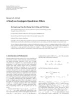
3.1. Candidate Sequence Generator in Complex Plane. To
search the symbols efficiently in the complex plane, it is
useful to construct a table of candidate symbol sequences
withinagivenregion[14]. First, a primitive block is defined
to be a square block bounded by
{1+j,1− j,−1+j,−1 − j}.
The complex plane can be regarded as consisting of a lot
of primitive blocks placed at equal distances. In Figure 2,a
received symbol is located at y
i
surrounded by four nearest
candidate symbols 41, 42, 49, and 50 in the constellation
diagram. A candidate symbol sequence, 49-50-41-42, can
then be formed according to their distance from y
i
in
ascending order. Consider then the square area centered at
the origin and surrounded by the candidate symbols 27,
28, 35, and 36. Shifting the symbols 41, 42, 49, and 50 to
the symbols 27, 28, 35, and 36, respectively, a location y
i,M
corresponding to y
i
can be identified. A new candidate
symbol sequence, 35-36-27-28, can be identified likewise
according to their distance from y
i,M
in ascending order.
Apparently the relation in terms of the distance from y
i
to nearby candidate symbols remains unchanged after the
coordination transformation. On the other hand, since the
EURASIP Journal on Advances in Signal Processing 5
i-th layer
P
1
i
P
2
i
P
k
i
···
··· ··· ···
···
B
1.1
i
−1
B
1,M
i
−1
B
2,1
i
−1
B
2,M
c
i−1
B
k,1
i
−1
B
k,M
i
−1
P
1.1
i
−1
P
1.M
c
i−1
P
2,1
i
−1
P
2,M
c
i−1
P
k,1
i
−1
P
k,M
c
i−1
Sort algorithm
(i-1)-th layer
P
1
i
−1
P
2
i
−1
P
k
i
−1
P
k
i
−1
P
m,n
i
−1
= P
m
i
−1
+ B
m,n
i
−1
Figure 1: Illustration of the multi-index operation.
25
26
27
28
33
34
35
36
41
42
43
44
49
50
51
52
1. Modulo
2. Add offset
−1
1
3
5
Quadrature
−113 5
QAM constellation
y
i,M
y
i
In-phase
Figure 2: Modulo operation of the search center.
symbols are placed symmetrically in the complex plane, once
the relation between a received symbol and the associated
candidate symbol sequence in one of the four quadrants is
obtained, those in the other three quadrants can be readily
derived. Next, Figure 3 shows quadrant I of the solid-
line square area in Figure 2. The area is divided into 30
segments (we will explain how to partition the specified
square area later). It can be verified that all symbols inside
any given segment share the same candidate symbol sequence
of k symbols, where k
= 11 in Figure 3.Forexample,
consider two symbols “c” and “d” inside segment 01 and
evaluate the distances between all valid candidate symbols
and the two points. It is straightforward to verify that the
resulting two candidate sequences are identical, that is,
{1+
j,
−1+j,1− j,−1 − j,1 + j3,−1+j3,3 + j,−3+j,3−
j,−3 − j,1 − j3}. For other segments, the same result
applies.
01
02
03
04
05
06
07
08
09
10
11
12
13
14
15
16
17
18
19
20
21
22
23
24
25
26
27
28
29
30
0
0.1
0.2
0.3
0.4
0.5
0.6
0.7
0.8
0.9
1
Quadrature
010.20.30.40.50.60.70.80.91
∗
c
∗
d
In-phase
Figure 3: Partition of the search segments.
Using the above properties, we can construct a table of
candidate symbol sequences of the K nearest constellation
symbols for all symbols bounded by
{1+j,1− j, −1+j, −1−
j} instead of generating approximated path weights [30, 31].
Due to the symmetry of 16-QAM and 64-QAM, a simple
transformation allows symbols in the region bounded by
{1+j,1− j,−1+j,−1 − j} in quadrants II, III, and IV
to use the same table as quadrant I. Any symbol located
within the bounded region is first mapped to quadrant I by
a simple transformation. The transformed result acts as the
search center for finding the k nearest candidate symbols by
looking up the table of the symbol sequences, where k is a
specified number. When the candidate symbol sequence
{x
i
}
is found, it can easily be transformed back to the original
quadrant. Figure 3 shows the partition of the search segments
in quadrant I, and the corresponding symbol sequences are
listed in Table 1,wherek
= 11 is chosen as an example. This
6 EURASIP Journal on Advances in Signal Processing
Table 1: List of candidate sequences.
Segment
ID
Candidate sequence
01
1+j,
−1+j,1− j,−1 − j,1+ j3, −1+j3, 3 + j,−3+
j,3
− j, −3 − j,1− j3
02
1+j,
−1+j,1− j,−1 − j,1+ j3, −1+j3, 3 + j,−3+
j,3
− j, −3 − j,3+ j3
.
.
.
.
.
.
29
1+j,1
− j, −1+j,3+ j, −1 − j,3− j,1+ j3, −1+
j3, 3 + j3, 1
− j3, −1 − j3
30
1+j,1
− j, −1+j,3+j, −1 − j,3− j,1+ j3, 1 −
j3, −1+j3, 3 + j3, −1 − j3
table can be constructed in advance by the following offline
procedure:
First, the bounded square area by
{1+j,1, j,0} is divided
into u
2
grids, by (u − 1) equally space horizontal and (u − 1)
equally space vertical lines, where u is chosen according to the
required resolution. The corresponding distances between
all valid candidate symbols and the center of each grid,
which represents all possible received symbols within, are
then evaluated. Next, by using some sorting procedure,
the associated candidate sequence of any possible received
symbol can be determined. Finally, all these possible symbols
are rearranged into several search segments such that each
segment has the same candidate sequence. By this approach,
it is easy to tackle any predefined constellation rotation
during run-time processing. The following describes the
run-time operation in detail.
For any given search center y
i
in the complex plane, the
CSG first rounds it to the relative position y
i,M
which lies
inside the region bounded by
{1+j,1− j, −1− j, −1+j}. This
modulooperationisdepictedinFigure2, and the associated
relationship is described as follows:
for Re(y
i
)
X
offset =
Re
y
i
+mod
Re
y
i
,2
Re
y
i,M
=
Re
y
i
−
X offest
(11)
for Im(y
i
)
Y
offset =
Im
y
i
+mod
Im
y
i
,2
Im
y
i,M
=
Im
y
i
−
Y
offest
.
(12)
Figure 4(a) shows the modulo unit of Re(y
i
) based on the
2’scomplementproperty,whichisefficiently implemented
by a single adder and a few bit manipulations. S is the sign
bit (i.e., MSB) of Re(y
i
)andb
0
is the LSB of the integer
part of Re(y
i
). Since the modulo operation of Im(y
i
) is the
same as Re(y
i
), the modulo circuits of Im(y
i
)andRe(y
i
)
are identical.
In the next step, if y
i,M
lies in quadrant II, III, or IV,
the CSG unit maps y
i,M
into quadrant I by rotating π/2, π
and 3π/2, respectively. Figure 4(b) shows this transformation
circuit. The multiplexers chooses a right data path based
on the sign bits of Re(y
i,M
)andIm(y
i,M
). The coordinates
dx
t and dy t denote the transformed values of Re(y
i,M
)and
Im(y
i,M
), respectively.
The set (dx
t, dy t) is sent to the candidate generator
unit to generate the desired candidate sequence
{x
i
}
k
i
=1
using
a table lookup operation. The contents of the segment
identification (ID) and its corresponding candidate sequence
are stored in ROM 1 and ROM 2, respectively, as shown in
Figure 5, where the hardware architecture of the candidate
generator is depicted. The found candidate symbol is first
rotated into its original quadrant, and then the offset pair
(X
offset, Y offset) is added to the coordinates of the found
candidate symbol. After the constellation restoration, the
constellation boundary checker checks whether or not the
found symbol lies inside the constellation boundary. If the
found restored symbol is a legal one, the distance calculator
calculates the value of
y
i
− x
i
2
. Multiplying the value of
y
i
− x
i
2
by r
2
i,i
and adding the parent weight P
i+1
to the
multiplied result, we obtain the path weight P
i
of the found
symbol. The CSG can efficiently generate the coordination
pairs of valid candidates and the associated path weights
according to their path weights in an ascending order for each
given received symbol. From Figure 5, the major hardware
cost of the CSG involves 3 multipliers, 12 adders, and 2
ROMs. The ROM sizes (number of logic gates) are 2116
(ROM 1, with u
= 32) and 731 (ROM 2), respectively,
according to the Synposys synthesis tools.
For any given symbol and its neighbors, which share
the same candidate sequence, the candidate sequence is
generated from the k nearest constellation symbols by sorting
their relative distance to the search center though these
distance values are different for each different search center.
The proposed CSG utilizes this property to generate a
candidate sequence in ascending order and calculates the
associated path weights so as to avoid a heavy load of path
weight evaluations and sorting. Based on this concept, we can
choose the appropriate k to fit the system requirement. The
ROM size expands quickly when a large value of k is chosen.
To remedy this, we can divide k into a set
{k
i
}
p
i
=1
,where
p
i
=1
k
i
= k such that the ROM can be kept at a realizable
size.
3.2. Architecture of Highly Parallel Comparison Circuit
(HPCC). The sorting operations in the K-Best decoder
dominate the major complexity at each search layer. Hence,
sorting is a critical factor in reducing the complexity of
the K-Best SDA. The previously proposed CSG module can
be applied to the K-Best SDA by exploiting the inherent
partial orders coming with the property of CSG. This
can be efficiently accommodated by applying the K-merge
algorithm [30, 32]. For a more practical implementation, an
efficient architecture that can effectively reduce the sorting
complexity is needed.
Recall the definitions of branch weights and PED in
Section 2.LetP
1
i
, P
2
i
, , P
K
i
denote the K smallest PEDs in
the ith layer. After full-path expansion, we have KM
c
PEDs
P
1,1
i
−1
, P
1,2
i
−2
, , P
1,M
c
i−1
, , P
K,1
i
−1
, P
K,2
i
−2
, , P
K,M
c
i−1
at layer i,where
P
m,n
i
−1
stands for the PED of the nth path expanded from the
EURASIP Journal on Advances in Signal Processing 7
Fractional part
Integer part
1
Re(y
i
)
Sb
0
+
Re(y
i,M
)X offset =[X out:0]
X
out
(a)
00
01
10
11
00
01
10
11
MUX
MUX
Re(y
i,M
)
Im(y
i,M
)
dx
t
dy
t
[Re(y
i,M
)·MSB Im(y
i,M
)·MSB]
−1
−1
(b)
Figure 4: (a) Modulo unit of Re(y
i
). (b) Transformation unit of y
i,M
.
MUX
MUX
0
1
0
1
2
2
2
2
ROM 1
Upcounter
(0
∼10)
clk
Constellation
restoration
[Im(y
iM
)·MSB Re(y
i,M
)·MSB]
Segment
ID
ROM 2
Re(y
i
)Im(y
i
)
Figure 4(a)
Re(y
iM
)Im(y
iM
)
Figure 4(b)
[X
out:1]
[Y
out:1]
dx
t
dy
t
+
+
−
−
(·)
2
(·)
2
Distance
calculator (r
i,i
)
2
Parent weight
P
i−1
Cnstellation size M
c
Cnstellation
boundary
checker
en
Upcounter
(0
∼10) clk
Valid number
clk
Q
clk
Candidate
pairs
Va li d
indicator
Q
clk
Node
weight
+
+
Figure 5: Hardware architecture of the candidate generator.
mth parent node at layer i. Moreover, based on the sorted
results from the ith layer and the generated sequence from
the proposed CSG module, we have P
1
i
<P
2
i
< ··· <
P
K
i
and P
j,1
i
−1
<P
j,2
i
−1
< ··· <P
j,k
i
−1
for each 1 ≤ j ≤
k. Selecting the node with the smallest PED from the set
{P
1,1
i
, P
2,1
i
, , P
K,1
i
} is equivalent to finding the smallest PED
from the full path expansion set containing KM
c
nodes.
These operations are illustrated in Figure 6. Exploiting these
properties instead of using traditional sorting algorithms, we
can realize an efficient comparison architecture for the K-
Best sorting at each stage that avoids full path evaluation and
significantly reduces the sorting complexity. Figure 7 depicts
this hardware architecture, and the following describes its
operation.
The output sequence of the CSG module naturally forms
a set in ascending order according to the evaluated PEDs
while performing the Nth layer search. We, therefore, only
need to conduct a single coordination transformation and K
path weight calculations. The generated results serve as the
parent nodes of the next layer.
To search in the (i
− 1)th layer, we first calculate
{P
1,1
i
−1
, P
2,1
i
−1
, , P
K,1
i
−1
} and feed them into the HPCC. The can-
didate node with the smallest PED among these candidates
is obtained immediately after (K
− 1) compare-and-select
(CAS) operations. If the chosen node comes from the pth
parent node, then the P
p
i
+B
p,2
i
−1
PED is calculated, overwriting
the previously chosen node. The node with the 2nd smallest
PED is obtained after log
2
K CAS operations (only log
2
K
8 EURASIP Journal on Advances in Signal Processing
P
1
i
P
2
i
P
j
i
P
K
i
P
1,1
i
−1
P
2,1
i
−1
P
j,1
i
−1
P
K,1
i
−1
P
1,2
i
−1
P
2,2
i
−1
P
j,2
i
−1
P
K,2
i
−1
P
1,k
i
−1
P
2,k
i
−1
P
j,k
i
−1
P
K,k
i
−1
HCCP
Sorted output
sequence from CSG
P
m,1
i
−1
≤···≤P
m,k
i
−1
1≤ m ≤ K
Output
P
1
i
−1
P
1
i
−1
= min{P
m,1
i
−1
}
= min{P
m,n
i
−1
}
1
≤ m ≤ K
1
≤ n ≤ k
··· ···
······
.
.
.
.
.
.
.
.
.
.
.
.
Figure 6: Illustration of the HPPC operations.
MUX
Q
Q
Q
Q
Q
Q
Q
Q
Q
Q
Q
Q
CAS
CAS
CAS
CAS
CAS
CAS
CAS
CAS
CAS
CAS
CAS
CAS
1
0
Stage # 1 Stage # 2
Stage # 3
Stage
#log
2
(K)
Encoder
MSB
0
MSB
1
MSB
(k-2)
Indicator for
min
weight
module [0
··· (K − 1)]
MSB
i
−
.
.
.
.
.
.
.
.
.
···
Figure 7: HPCC architecture.
results need be re-computed). Repeating this procedure, we
can successfully select K candidate nodes with the smallest
PEDs from the entire valid candidate set. The survival set acts
as the parent nodes of the (i
− 2)th layer. In searching the
nodes in each layer, we use K coordination transformation,
(2K
−1) path weights evaluations, and (K−1)(1+log
2
K)CAS
operations. Note that the computational complexity of this
approach is nearly fixed and independent of the constellation
size M
c
of the transmitted symbols. Furthermore, the nodes
in the survival set still exhibit an ascending order according
to their PEDs. In the final search layer, that is, the 1st layer,
we only need to choose the node with the smallest PED
as the detection result. Hence, it takes only K coordination
transformation, K PEDs evaluations, and (K
− 1) CAS
operations.
Compared with the winner path expansion method [33,
34], the proposed architecture, which is also frequently found
in Viterbi decoder for choosing the minimal path metric,
can avoid performing unnecessary operations thanks to the
property of parallel computation. Moreover, it requires a
smaller number of CAS (K
− 1) than that of the conventional
bubble sort method (K).
3.3. Complexity Advantages. Through the combination of
the two proposed modules, we only need K coordination
transformations, (2K
− 1) PED evaluations, and (K − 1)(1 +
log
2
K) CAS operations in each layer to obtain K nodes with
the smallest PEDs, regardless of the constellation size. These
PEDs only need to be calculated when they are fed into the
HPCC. Hence, the proposed architecture avoids exhaustive
EURASIP Journal on Advances in Signal Processing 9
path weight evaluations as required in the conventional
bubble sort architecture.
Previous methods attempt to reduce computational
complexity by eliminating the number of visited nodes based
on the probability or statistical properties of the additive
noise. These methods provide an approximate solution and
barter decoding performance for complexity reduction. As
an alternative, this paper presents another way to reduce
complexity with the premise of carrying on high-quality
decoding results. The proposed approach utilizes operation
decomposition, reconstruction, and associated efficient
hardware architecture to select and evaluate only the most
promising candidate symbols. The proposed method also
significantly reduces computational complexity and provides
an efficient solution with a nearly fixed throughput. These
advantages are further enhanced when a larger constellation
size is adopted. Although the proposed method incurs the
extra cost of coordination transformation and restoration,
it eliminates many path calculations and sorting operations
and provides the same performance as the conventional
K-Best SDA.
4. Proposed Search Strategy for
Near-ML Performance
One way to reduce the complexity of the conventional
K-Best SDA is to choose a smaller number of survival
nodes in each layer. However, this can cause performance
degradation in term of error rate. Instead of choosing a
sufficiently large K to achieve the near-ML performance,
a new search strategy is proposed. The proposed search
strategy preserves all candidate symbols and performs the
ML search in the preceding layers when dealing with poor
channel conditions. Only K candidates are kept for the
remaining lower layers. The following sections show how
to determine the number of layers performing the ML
search.
4.1. Preprocessing with Column Permutation. The channel
matrix can be preprocessed with various techniques to
reduce the complexity of candidate search and/or improve
the performance of the K-Best SDA. Many preprocessing
techniques can be used for this purpose, including column
permutation [13], scaling [35], and lattice reduction [36].
In this paper, column permutation is adopted, in which the
permutation order is determined according to the column
norms of the channel matrix in ascending order. Given the
QR decomposition of the ordered channel matrix H
o
=
Q
o
R
o
, we characterize below the cumulative distribution
function (cdf) of the square of the diagonal entries of R
o
denoted by r
2
o,i,i
(see the appendix):
for i
= 1
F
r
2
o,i,i
(
r
)
=
r
0
N!
(
N
− 1
)
!
(
M − 1
)
!
⎡
⎣
M−1
k=0
x
k
k!
e
−x
⎤
⎦
N−1
· x
M−1
e
−x
dx,
(13)
for 2
≤ i ≤ N
F
r
2
o,i,i
(
r
)
= C
ii
1
0
r/s
0
⎡
⎣
1 −
M−1
k=0
x
k
k!
e
−x
⎤
⎦
i−1
⎡
⎣
M−1
k=0
x
k
k!
e
−x
⎤
⎦
N−i
· x
M−1
e
−x
(
s
)
M−i
(
1
− s
)
i−2
dx ds,
(14)
where
C
ii
=
N!
(
N
− i
)
!
(
M − i
)
!
(
i − 1
)
!
(
i − 2
)
!
. (15)
Comparing (13)–(15) with the results of [13], the
ordering mechanism increases E[r
2
i,i
] in the preceding layers,
producing two main benefits. First, for a fixed K in the K-
Best SDA, increasing E[r
2
i,i
] in the preceding layers reduces
the effective search range of the candidates. This in turn
reduces the probability of the ML solution being dropped in
the preceding layers. Another benefit is that it constrains the
growth of the tree and hence reduces search complexity.
4.2. Proposed Search Strategy. For the Nth layer, the candi-
date symbol should satisfy the following search constraint
according to (7):
y
N
− x
N
2
≤
d
r
N,N
2
. (16)
Clearly, 1/r
N,N
will enlarge the constraint region when r
N,N
is
smaller than 1. In this case, the probability of the ML solution
being dropped will increase when only K nodes are kept in
the Nth layer. To avoid performance degradation, conducting
the ML search in the preceding layers [27] is one of the
approaches usually adopted. To further reduce the compu-
tational complexity, we propose to perform the ML search in
the ith layer only when any r
i,i
,whereN − L
ML
+1≤ i ≤ N,
is smaller than a given threshold T
r
,withL
ML
denoting the
number of layers performing the ML search; the threshold T
r
will be decided later. This proposed search strategy is named
conditional-ML (CML) search. Hence, the number of layers
performing the ML search depends on the distribution of
r
2
i,i
. Figures 8(a) and 8(b) show the impact of r
N,N
on the
constrained search region. Based on the derived results in
(13)–(15), we can systematically determine the number of
layers performing the ML search under different M and N.
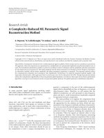
Figure 9(a) shows the cdf curves of r
2
o,i,i
for the 4 × 4
MIMO channel. The probability of r
2
o,i,i
< 1 in the 4th layer is
larger than that in the other layers. Hence, only the 4th layer
needs to perform the ML search. Figure 9(b) shows the cdf
curves of r
2
o,i,i
for the 8 × 8 MIMO channel. In this case, the
probabilities of r
2
o,i,i
< 1 in the 8th and the 7th layers are larger
than that in the other layers. However, the number of possible
candidates in the 7th layer is (M
c
)
2
in the worst case, which is
too large to store in a hardware implementation when M
c
is
large. Hence, we keep all possible candidates in the 8th layer.
For the 7th layer, we first find all possible candidates and keep
K survival nodes with the minimum path weights.
10 EURASIP Journal on Advances in Signal Processing
−1
1
3
5
7
Quadrature
−3 −11 3 5
QAM constellation
In-phase
(a)
−1
1
3
5
7
Quadrature
−3 −11 3 5
QAM constellation
In-phase
(b)
Figure 8: Search constraints of the Nth layer with d
= 1.1. (a) r
N,N
= 1. (b) r
N,N
= 0.33.
0
0.1
0.2
0.3
0.4
0.5
0.6
Probability
00.51 1.5
(r
o,i,i
)
2
Layer 1
Layer 2
Layer 3
Layer 4
(a)
0
0.05
0.1
0.15
0.2
0.25
0.3
0.35
0.4
0.45
0.5
Probability
0
0.20.40.60.80.11.2
(r
o,i,i
)
2
Layer 1
Layer 2
Layer 3
Layer 4
Layer 5
Layer 6
Layer 7
Layer 8
(b)
Figure 9: Cdf curves of r
2
o,i,i
.(a)4× 4 MIMO channel. (b) 8 × 8 MIMO channel.
Next, we discuss how to decide the threshold T
r
.Recall
that for the Nth layer, a search for the candidate symbols
should satisfy the following constraint:
r
2
N,N
y
N
− x
N
2
≤
(
d
)
2
. (17)
The proposed algorithm only keeps the k constellation sym-
bols nearest to y
N
where k = min(K, 11); hence, the value
of
y
N
− x
N
2
has a limited range. Number 11 is chosen
according to [37], which suggests that producing 11 can-
didate symbols yields quite good performance for practical
applications. Therefore, we configure CSG to generate only
11 candidate symbols to reduce the implementation cost.
From the previous argument and (17), it is straightforward
to see that the threshold T
r
can be chosen based on the
following criterion:
T
r
D ≥ E
(
d
)
2
, (18)
D
= min
(
D
K
, D
11
)
,
(19)
EURASIP Journal on Advances in Signal Processing 11
where D
K
and D
11
denote the distances from the Kth
and 11th nearest constellation symbols to s
N
,respectively.
E[(d
)
2
] is the expected value taken with respect to the
channel statistics; it is used in place of (d
)
2
because d
is typically a random variable depending on the channel
condition and SNR [10, 13].
By using (18), when the k nearest constellation symbols
do not cover all the symbols inside the circle with a
radius of E[(d
)
2
]
1/2
, the ML search can be activated to
retain all valid symbols. However, this will incur complexity
increase because the probability of performing the ML search
increases. The threshold T
r
thus acts as a tradeoff parameter
between complexity and performance. Since E[(d
)
2
]varies
with SNR, we can choose E[(d
)
2
] corresponding to the
SNR at which the symbol error rate of the proposed K-
Best SDA deviates from that of the ML detector by a certain
normalized amount δ. This ensures that the performance of
the proposed K-Best SDA can be made close to ML detection.
When applying the criterion in (18) to the (N
−1)th layer and
below, the obtained threshold is sure to be smaller than the
threshold of the Nth layer because the distance contributed
by the Nth layer is a positive value. Thus, we can use the
threshold of the Nth layer for other layers. In summary, the
proposed CML search strategy only needs to check whether
the values of r
o,i,i
, that are already available from the QR
decomposition, are smaller than T
r
. It is not necessary to
design any extra circuits to estimate the channel conditions
for adjusting K as in [24].
By the proposed criterion in (18)-(19), the system per-
formance is insensitive to the choice of K and the number of
candidates generated by the CSG module. This is in contrast
to the conventional K-Best SDA, in which the value of K
must be large enough, usually close to the constellation size
M
c
, to archive near-ML performance. Using the proposed
criterion with the self-adjustment mechanism, the proposed
K-Best SDA can choose a smaller K, as small as a half of
M
c
, to archive near-ML performance. In fact, when a smaller
value of K is chosen or the GSC module generates a shorter
candidate sequence, the ML search will be activated more
frequently trying to retain the possible ML solution.
The overall complexity of the proposed K-Best SDA can
be predicted based on the complexity of the adopted sorting
architecture, CML search procedure, choice of the value of K,
the number of generated candidates of the CSG module, and
the activation probability of the ML search. The decoder can
thus achieve near-ML performance under a given complexity
constraint without requiring a large value of K.
4.3. Joint 2-Layer ML Search Algorithm. According to the
derived cdf of r
2
o,i,i
in (13)–(15) and observation in the
previous sections, we only need to conduct a 2-layer full
search in the worst case, which involve choosing K survival
nodes with the smallest path weights among (M
c
)
2
nodes. In
the original 2-layer ML search in the complex plane, for any
received symbol, we need to evaluate all accumulated path
weights between the search center and all valid candidate
symbols while performing a full search of two layers. We then
select K nodes with the smallest accumulated path weights.
L
r
P
2
P
1
O
Figure 10: Geometrical relationship illustrating the adopted prop-
erty for computation reduction.
Using the previously developed CSG and HPCC mod-
ules, we here propose an efficientprocedurewhichonly
requires a minor modification of the control path of the
HPCC. This modified procedure significantly reduces the
computational burden and hardware implementation cost.
The following describes the proposed procedure in detail.
First, for any received symbol in the complex plane, we
evaluate the distances between the received symbol and all
valid candidate symbols which lie on the same row of the
square lattice before starting the sorting procedure. Consider
the geometry shown in Figure 10.Letr lie on line L,which
is perpendicular to
p
1
p
2
and intersects with p
1
p
2
at o.Itis
easy to show that if
op
1
> op
2
then rp
1
> rp
2
. Using this
property, these candidate symbols can be ordered by their
coordinate values on the x-axis following the SE enumeration
rule [12]. Therefore, a table containing the row vectors of
sorted candidate symbols for each x value would suffice and
efficiently simplifies the sorting process [38].
Second, for any square lattice with M
c
symbols, these
candidate symbols can be divided into
M
c
groups. Each
symbol in the same group has the same y-axis coordinate
value. Based on the prepared table, the procedure can
efficiently generate
M
c
groups. Each group contains
M
c
sorted candidate symbols for each received signal without
any extra sorting operation. The structure of each sorted
group is the same as the output sequence of the proposed
CSG module in ascending order. Therefore, utilizing the
HPCC, after
M
c
+ K − 1 path evaluations and (
M
c
− 1) +
(K
− 1)log
2
M
c
CAS operations, the proposed procedure
can generate K candidates with the smallest PEDs for each
given received symbol. These selected K symbols are again
arranged in ascending order according to their PEDs. Note
that only these promising candidates are considered and
completely evaluated. Finally, when a full search of two layers
is required, it is only necessary to repeat M
c
times for M
c
possible parent symbols to generate a total of KM
c
promising
symbols and divide them into M
c
sorted groups. Each group
is sorted in ascending order according to the evaluated PEDs.
The HPCC is then utilized to choose the K survival symbols
with the smallest PEDs. This can be done efficiently thanks
to the naturally ascending order of each group.
The above procedure can achieve the same result as
the ML exhaustive search, but its complexity is significantly
12 EURASIP Journal on Advances in Signal Processing
Table 2: Computational complexity of proposed K-Best SDA (excluding interference cancellation).
ML search deactivated
ML search activated
1st layer
search
2nd layer search
Joint 2-layer ML
search
3rd
∼ (N − 1)th
layer search
Nth layer
search
CAS 0 (K − 1)(1 + log
2
K)
M
c
(K −1)log
2
(
M
c
)+
M
c
(
M
c
− 1) +
m(2K
− 1) + (m −
1)[log
2
(m) − 1]
(K
− 1)(1 + log
2
K)(K − 1)
Path
Accumulation
0(2K
− 1) M
c
(
M
c
+ K − 1) (2K − 1) K
Path calculation K (2K
− 1) M
c
+M
c
(
M
c
+K − 1) (2K − 1) K
Where m = [M
c
/k], if mod(M
c
, k) = 0andm = [M
c
/k]+1,otherwise.
Table 3: Computational complexity of conventional K-Best SDA in
real domain (excluding interference cancellation).
1st layer
search
2nd
∼
(2N − 1)th
layer search
2Nth layer
search
CAS K
M
c
K
2
M
c
(K
M
c
− 1)
Path Accumulation 0 K
M
c
K
M
c
Path calculation
M
c
K
M
c
K
M
c
reduced when K is small. The procedure fully reutilizes
the previously proposed hardware architecture as described
in Section 3 except an extra memory is required for the
intermediate storage. It also inherits the advantages of CSG
andHPCCwhichavoidtheheavyloadinpathweight
computation and sorting.
Ta bles 2 and 3 show the detailed computational complex-
ity of the proposed K-Best SDA and the conventional K-Best
SDA, respectively. Comparing the two tables, the required
complexity of proposed K-Best SDA is approximately
M
c
times lower than the conventional one and is insensitive to
the constellation size M
c
, as mentioned earlier in Section 3.2.
Although extra computations are needed when the CML
search is activated in the proposed SDA, the probability of
activation is small, as long as the channel is not severely ill
conditioned. Therefore, the total required complexity of the
proposed K-Best SDA can still be kept lower than that of the
conventional SDA. As a final remark, since the proposed K-
Best SDA can work with a smaller number of search layers
and smaller value of K, compared to the conventional K-Best
SDA, it has the potential of reducing the decoding latency of
the latter because the decoding latency mainly depends on
the number of search layers and required processing time per
search layer, which in turn depends on K.
5. Computer Simulations and Discussions
This section simulates the symbol error rate (SER) perfor-
mance and complexity of the proposed K-Best SDA and
compares it with the SE SDA and conventional K-Best
SDA [17]. Although many variants of the K-Best SDA have
been proposed, the conventional one has the best decoding
performance and is chosen here as a benchmark. For a fair
comparison in each simulation, the preprocessing technique
mentioned in Section 4.1 is applied to all algorithms.
Complexity is measured in terms of the average number
of floating point operations (flops). All real additions,
multiplications, memory read/write, and comparisons are
equally treated as flops. We set d
as the distance between the
Babai estimate and the received signal [10], and E[(d
)
2
]is
then obtained in advance for each SNR as the average from
100000 independent trials. In each simulation, we generate
100 noise realizations per channel realization, and at least
5000 channel realization for each SNR value. The SER is
obtained as the average from 500000 independent trials.
We first investigate the effectiveness of the proposed CML
strategy by comparing the performance of the complex K-
Best SDA, which is mentioned in Section 2, with various
configurations. An extreme value of K
= 4 is chosen for the
complex K-Best SDA incorporating CML. Note that K
= 4
is in general the maximal acceptable value for a MIMO-
OFDM system, where the ML solution needs to be obtained
for each subcarrier. The normalized deviation of SER is set
as δ
= 15%, the threshold T
r
is set as 0.42 according to
(18), and the corresponding probability of performing the
ML search is 9.08%, according to (13)–(15). On the other
hand, the K values of the conventional complex K-Best SDA
without CML are chosen as K
= 4,8, 12 for 4 × 4 16-QAM,
and K
= 4, 12,24 for 64-QAM, respectively, to illustrate
the performance difference. Figures 11(a), 11(b) show the
4
× 4 16-QAM and 64-QAM simulations of SER respectively.
From the results, the complex K-Best SDA incorporating
CML can significantly improve the decoding performance
with a small K value. The reason is that the proposed
CML strategy keeps all possible candidates in the first search
layer when the channel is in a poor condition, significantly
reducing the probability of the ML solution being dropped.
The conventional complex K-Best SDA needs to choose K
=
12 and 24, respectively, to achieve the similar performance.
Such high K configurations would inevitably increase the
computational complexity, decoding latency and infeasibility
for practical MIMO-OFDM systems. For demonstration, we
also include the cases of K
= 8andK = 12 for the complex
EURASIP Journal on Advances in Signal Processing 13
K-Best SDA incorporating CML for 16-QAM and 64-QAM
respectively. It is evident that both can achieve nearly the
same performance as the ML detector.
Next, we evaluate the SER performance and complexity
of the proposed complex K-Best SDA incorporating the CML
strategy. Figures 12(a), 12(b) and 13(a), 13(b),respectively,
show the 4
× 4 16-QAM and 64-QAM simulations of SER
and complexity with K
= 8. The normalized deviation of
SER is set as δ
= 5% and δ = 10%, respectively, and
the threshold T
r
is set as 0.291 and 0.3532, respectively,
according to (18), and the corresponding probability of
performing the proposed ML search is 4.26% and 5.62%,
respectively, according to (13)–(15). Comparing Figure 12(a)
with Figure 13(a), the SER curves of the proposed K-Best
SDA and the SE SDA are nearly the same. This shows that
the threshold constraint significantly reduces the probability
of performing the ML search, and there is almost no
performance degradation in the proposed K-Best SDA. In
contrast, the SER of the conventional K-Best SDA tends
tobecomesaturatedathighSNR.Thisisduetothefact
that the conventional K-Best SDA with a smaller K drops
the ML solution with a high probability when the channel
is in poor conditions, which always occurs with a certain
probability in practice. In the 64-QAM case, the proposed
K-Best SDA achieves nearly a 3 dB gain over the conventional
K-Best SDA at SER
= 10
−3
. Note that this performance gap
between the proposed K-Best SDA and a conventional one
is larger than that of the 16-QAM case. This is because the
probability of the ML solution being dropped increases as
the modulation symbol alphabet becomes larger [17]. In
contrast, the proposed CML search strategy keeps all possible
candidates in the preceding layers, significantly reducing the
probability of the ML solution being dropped. Comparing
Figure 12(b) with Figure 13(b), the proposed K-Best SDA
has higher complexity than that of the SE SDA in the high
SNR regime. This is due to the fact that the proposed K-
Best SDA visits more candidate symbols than the SE SDA
when the number of layers N is smaller. As shown in the
simulation cases, the complexity of the SE SDA varies with
SNR. This is not desirable in practice, because a steady SNR
is not achievable in realistic wireless environments, such that
the decoding throughput of the SE SDA cannot be stable. In
contrast, the proposed K-Best SDA provides a nearly fixed
throughput, with excellent performance and low complexity.
The proposed efficient architecture reduces the number of
path weight evaluations and sorting operations in each layer.
As a result, the proposed K-Best SDA exhibits near-ML
performance and reduces 46.62% and 58.14% complexity,
respectively, over the conventional K-Best approach using
the same K.
Figures 14(a) and 14(b) show the 8
× 8 16-QAM
simulations of SER and complexity with K
= 14. The
normalized deviation of SER is set as δ
= 15% and
the threshold T
r
is set as 0.833, and the corresponding
probability of performing the proposed ML search is 43.9%.
The probability of performing the ML search is higher than
that of the 4
× 4 case because the probability of the ML
solution being dropped in the K-Best SDA is higher in the 8
×
8 case. Again, the performance of the proposed K-Best SDA is
better than the conventional K-Best SDA, and the complexity
of the proposed K-Best SDA is lower than that of the SE
SDA and the conventional K-Best SDA. Compared with the
conventional K-Best SDA, the proposed method decreases
complexity by more than 41.75%. Because the number of
search layers is larger in this case, the proposed method
reduces more complexity in path evaluations and sorting
operations. In the 8
× 8 case, the value of K must be set larger
to reduce the probability of the ML solution being dropped
in the preceding layers. Hence, the gap in complexity between
the proposed K-Best SDA and the conventional K-Best SDA
is smaller than that in the 4
× 4case.Wecanfurtherimprove
the performance of the proposed K-Best SDA by choosing a
higher threshold.
Figures 15(a) and 15(b) show the 8
× 8 64-QAM simula-
tions of SER and complexity with K
= 32. The normalized
deviation of SER is set as δ
= 15% and the threshold T
r
is
set as 1.143 and the corresponding probability of performing
the ML search is 65.8%. In this case, the proposed K-Best
SDA still works better than the conventional K-Best SDA.
The gap in complexity between the proposed K-Best SDA
and the conventional K-Best SDA is smaller than that in the
8
× 8 16-QAM case. This is because a higher threshold value
causes the ML search operations to occur more frequently
though the proposed efficient sorting method reduces much
more complexity for a larger modulation alphabet. The
proposed CML search procedure significantly reduces the
amount of path evaluations but induces extra memory
read/write and table access operations. Nevertheless, the
proposed K-Best SDA still has lower average complexity
than the conventional one. Finally, under the same channel
conditions, the conventional K-Best SDA requires K
= 52 to
achieve near-ML performance. The configuration increases
the computational complexity and decoding latency. The
proposed decoder with K
= 32 can provide nearly the same
performance, reducing 53.45% computational complexity
over the conventional K-Best SDA with K
= 52.
This section simulates the SER performance and com-
plexity of the proposed SDA and compares it with the SE SDA
and the conventional K-Best SDA. Although the value of r
o,i,i
does not directly reflect the channel condition in all cases,
the proposed criterion does help the decoder successfully
produce a near ML solution over poor channels, without
always performing the ML search in the preceding layers.
This systematic approach thus requires fewer ML search
layers than previous methods [23, 27]. The simulation results
confirm that the proposed decoder exhibits excellent perfor-
mance and requires lower complexity than the conventional
K-Best SDA. It is also worth noting that the performance of
the proposed decoder is close to that of the SE SDA (i.e., ML
performance).
6. Conclusions
In this paper, we propose a modified K-Best SDA with a new
sorting algorithm and search strategy to achieve near-ML
performance with low complexity. In conventional K-Best
SDA, path-weight evaluation and sorting operations for all
valid candidate symbols comprise the major computational
14 EURASIP Journal on Advances in Signal Processing
10
−5
10
−4
10
−3
10
−2
10
−1
10
0
SER
710131619222528
SNR (dB)
Complex K-BestSDAwithoutproposedCML(K
= 4)
Complex K-BestSDAwithoutproposedCML(K
= 8)
Complex K-BestSDAwithoutproposedCML(K
= 12)
Complex K-Best SDA with proposed CML (K
= 4)
Complex K-Best SDA with proposed CML (K
= 8)
MLD (4
× 4)
(a)
10
−4
10
−3
10
−2
10
−1
10
0
SER
15 18 21 24 27 30 33
SNR (dB)
Complex K-BestSDAwithoutproposedCML(K
= 4)
Complex K-BestSDAwithoutproposedCML(K
= 12)
Complex K-BestSDAwithoutproposedCML(K
= 24)
Complex K-Best SDA with proposed CML (K
= 4)
Complex K-Best SDA with proposed CML (K
= 12)
MLD (4
× 4)
(b)
Figure 11: Performance of complex K-Best SDA for 4 × 4 MIMO systems. (a) 16-QAM modulation. K = 4and8forcomplexK-Best SDA
incoporating proposed CML strategy; K
= 4K, 8, and 12 for regular complex K-Best SDAs. (b) 64-QAM modulation. K = 4 and 12 for
complex K-Best SDA incoporating proposed CML strategy; K
= 4K, 12, and 24 for regular complex K-Best SDAs.
10
−4
10
−3
10
−2
10
−1
10
0
SER
710131619222528
SNR (dB)
Conventional K-Best SDA (K
= 8) (4 × 4)
Proposed K-Best SDA (K
= 8) (4 × 4)
SE SDA (4
× 4)
(a)
10
3
10
4
Complexity
710131619222528
SNR (dB)
Conventional K-Best SDA (K
= 8) (4 × 4)
Proposed K-Best SDA (K
= 8) (4 × 4)
SE SDA (4
× 4)
(b)
Figure 12: Performance and complexity of SDA for 4 × 4 MIMO systems with 16-QAM modulation. (a) SER. (b) Complexity. K = 8for
K-Best SDAs.
cost in each search layer. The new CSG generates candidate
sequences in the complex plane instead of producing actual
path weights, thus making it possible for the child nodes of
each parent node to be sorted without any extra effort. Com-
bining the CSG with a highly parallel comparison circuit,
the proposed SDA can reduce computational complexity,
while maintaining the same performance as the conventional
K-Best SDA. To further improve decoding performance
and efficiency, the new search strategy performs the ML
search at a few preceding layers. A judicious criterion is
EURASIP Journal on Advances in Signal Processing 15
10
−4
10
−3
10
−2
10
−1
10
0
SER
15 18 21 24 27 30 33
SNR (dB)
Conventional K-Best SDA (K
= 8) (4 × 4)
Proposed K-Best SDA (K
= 8) (4 × 4)
SE SDA (4
× 4)
(a)
10
3
10
4
Complexity
15 18 21 24 27 30 33
SNR (dB)
Conventional K-Best SDA (K
= 8) (4 × 4)
Proposed K-Best SDA (K
= 8) (4 × 4)
SE SDA (4
× 4)
(b)
Figure 13: Performance and complexity of SDA for 4 × 4 MIMO systems with 64-QAM modulation. (a) SER. (b) Complexity. K = 8for
K-Best SDAs.
10
−4
10
−3
10
−2
10
−1
10
0
SER
7 1013161922
SNR (dB)
Conventional K-Best SDA (K
= 14) (8 × 8)
Proposed K-Best SDA (K
= 14) (8 × 8)
SE SDA (8
× 8)
(a)
10
4
10
5
10
6
Complexity
71013161922
SNR (dB)
Conventional K-Best SDA (K
= 14) (8 × 8)
Proposed K-Best SDA (K
= 14) (8 × 8)
SE SDA (8
× 8)
(b)
Figure 14: Performance and complexity of SDA for 8 × 8 MIMO systems with 16-QAM modulation. (a) SER. (b) Complexity. K = 14 for
K-Best SDAs.
proposed accordingly to determine when to activate the
ML search. Simulation results show that the proposed SDA
effectively reduces the complexity of the conventional K-Best
SDA, while offering superior SER performance at the high
SNR regime. Its decoding performance is close to the ML
performance even when the chosen value of K is small.
To facilitate practical applications of the proposed SDA,
a corresponding hardware architecture is also proposed. The
architecture is quite regular and utilizes standard hardware
elements without any extra complicated computational
modules. As such, the proposed SDA is suitable for real-
time applications and provides a promising solution for next
16 EURASIP Journal on Advances in Signal Processing
10
−4
10
−3
10
−2
10
−1
10
0
SER
17 20 23 26 29
SNR (dB)
Conventional K-Best SDA (K
= 32) (8 × 8)
Conventional K-Best SDA (K
= 52) (8 × 8)
Proposed K-Best SDA (K
= 32) (8 × 8)
SE SDA (8
× 8)
(a)
10
5
10
6
10
7
Complexity
17 20 23 26 29
SNR (dB)
Conventional K-Best SDA (K
= 32) (8 × 8)
Conventional K-Best SDA (K
= 52) (8 × 8)
Proposed K-Best SDA (K
= 32) (8 × 8)
SE SDA (8
× 8)
(b)
Figure 15: Performance and complexity of SDA for 8 × 8 MIMO systems with 16-QAM modulation. (a) SER. (b) Complexity. K = 32 for
proposed K-Best SDA; K
= 32 and 52 for conventional K-Best SDAs.
generation MIMO wireless communication systems such as
IMT-Advanced.
Appendix
The expression in (13)–(15) shows that reordering the
columns of H according to their vector norms in ascending
order leads to
H
o
=
h
o(1)
, h
o(2)
, , h
o(N)
,(A.1)
where
h
o(1)
≤h
o(2)
≤···≤h
o(N)
.From[13], h
o(i)
can be expressed as
h
o(i)
=
X
i
θ
i
,(A.2)
where X
i
is the ith order statistic of N independent
Gamma(M, 1) distributed random variables with X
1
≤ X
2
≤
··· ≤
X
N
and {θ
i
}s are i.i.d. uniformly distributed on the
unit sphere in
C
M
. Note that X
i
and θ
i
are independent. With
the QR decomposition of H
o
= Q
o
R
o
, we are now going to
characterize the distribution of the square of the diagonal
entries of R
o
denoted by r
2
o,i,i
.
Letting Q
o
= [q
o(1)
, q
o(2)
, , q
o(N)
] and performing the
QR decomposition of H
o
,weobtain
r
2
o,i,i
= X
i
⎡
⎣
1 −
i−1
k=1
q
H
o
(
k
)
θ
i
2
⎤
⎦
=
X
i
⎡
⎣
1 −
i−1
k=1
θ
2
i
(
k
)
⎤
⎦
=
⎧
⎨
⎩
X
i
,fori = 1
X
i
S
i
,for2≤ i ≤ N,
(A.3)
where
S
i
=
⎡
⎣
1 −
i−1
k=1
θ
2
i
(
k
)
⎤
⎦
,(A.4)
and θ
i
(k) denotes the kth element of θ
i
. Note that the second
equation holds due to the fact that the distribution of θ
i
is
invariant under the orthogonal transformation Q
o
.Toderive
the cdf of r
2
o,i,i
, we should first obtain the probability density
function (pdf) of X
i
and S
i
. The pdf of X
i
is available in [39]
as
f
X
i
(
x
)
=
N!
[
F
(
x
)
]
i−1
[
1
− F
(
x
)
]
N−i
f
(
x
)
(
i
− 1
)
!
(
N − i
)
!
,(A.5)
where
f
(
x
)
=
x
M−1
· e
−x
Γ
(
M
)
for x>0,
F
(
x
)
= 1 −
M−1
i=0
x
i
i!
e
−x
.
(A.6)
From [40], θ
i
can be modeled from a 2M-dimensional
random vector V
= [v
1
v
2
··· v
2M
]
T
with v
i
∼
i.i.d.N(0, 1), where
θ
i
(
k
)
=
v
2k−1
+ j · v
2k
V
=
v
2k−1
+ j · v
2k
v
2
1
+ v
2
2
+ ···+ v
2
2M
,(A.7)
due to the fact that θ
H
i
θ
i
= 1, S
i
can be rewritten as
S
i
=
⎡
⎣
1 −
i−1
k=1
θ
2
i
(
k
)
⎤
⎦
=
⎡
⎣
M−i+1
k=1
θ
2
i
(
k
)
⎤
⎦
,(A.8)
EURASIP Journal on Advances in Signal Processing 17
substituting (A.7) into (A.8), we have
S
i
=
M−i+1
k=1
θ
2
i
(
k
)
=
v
2
1
+ v
2
2
+ ···+ v
2
2
·
(
M
−i+1
)
v
2
1
+ v
2
2
+ ···+ v
2
2M
=
Q
i
P
i
,(A.9)
where Q
i
and P
i
are chi-square random variables with 2·(M−
i +1)and2M degrees of freedom, respectively.
The joint pdf of Q
i
and P
i
is
f
Q
i
,P
i
q, p
=
f
Q
i
q
·
f
P
i
−Q
i
p − q
=
f
χ(2·(M−i+1))
q
· f
χ(2i−2)
p − q
=
q
(M−i)
·
p − q
(i−2)
· e
−p/2
2
M
· Γ
(
M − i +1
)
· Γ
(
i − 1
)
,
for p>0, q>0,
(A.10)
where f
χ(k)
(x) denotes the pdf of the chi-square random
variable with k degrees of freedom. The pdf of S
i
can be
obtained by
f
S
i
(
s
)
=
∞
−∞
p
f
Q
i
,P
i
ps, p
dp
=
∞
0
p ·
ps
(M−i)
·
p − ps
(i−2)
· e
−p/2
2
M
· Γ
(
M − i +1
)
· Γ
(
i − 1
)
dp
=
s
(M−i)
·
(
1
− s
)
(i−2)
2
M
· Γ
(
M − i +1
)
· Γ
(
i − 1
)
∞
0
p
(M−1)
· e
−p/2
dp
=
s
(M−i)
·
(
1
− s
)
(i−2)
·
(
M
− 1
)
!
Γ
(
M − i +1
)
· Γ
(
i − 1
)
.
(A.11)
Since X
i
and S
i
are independent, the joint pdf of X
i
and S
i
is
f
X
i
,S
i
(
x, s
)
= f
X
i
(
x
)
· f
S
i
(
s
)
. (A.12)
The cdf of r
2
o,i,i
for 2 ≤ i ≤ N can be obtained by
F
r
2
o,i,i
(
r
)
=
1
0
r/s
0
f
X
i
,S
i
(
x, s
)
dx
ds
=
1
0
r/s
0
f
X
i
(
x
)
f
S
i
(
s
)
dx ds.
(A.13)
Finally, the cdf of r
2
o,i,i
is as follows:
for i
= 1
F
r
2
o,i,i
(
r
)
=
r
0
N!
(
N
− 1
)
!
(
M − 1
)
!
⎡
⎣
M−1
k=0
x
k
k!
e
−x
⎤
⎦
N−1
· x
M−1
e
−x
dx,
(A.14)
for 2
≤ i ≤ N
F
r
2
o,i,i
(
r
)
= C
ii
1
0
r/s
0
⎡
⎣
1 −
M−1
k=0
x
k
k!
e
−x
⎤
⎦
i−1
⎡
⎣
M−1
k=0
x
k
k!
e
−x
⎤
⎦
N−i
· x
M−1
e
−x
(
s
)
M−i
(
1
− s
)
i−2
dx ds,
(A.15)
where
C
ii
=
N!
(
N
− i
)
!
(
M − i
)
!
(
i − 1
)
!
(
i − 2
)
!
. (A.16)
Acknowledgment
This work was supported by the National Science Council of
Taiwan under Contract no. NSC 97-2221-E-009-056-MY2.
References
[1] E. Telatar, “Capacity of multi-antenna Gaussian channels,”
AT&T Bell Labs Internal Technical Memorandum, June 1995.
[2] G. J. Foschini and M. J. Gans, “On limits of wireless com-
munications in a fading environment when using multiple
antennas,” Wireless Personal Communications,vol.6,no.3,pp.
311–335, 1998.
[3] S. M. Alamouti, “A simple transmit diversity technique for
wireless communications,” IEEE Journal on Selected Areas in
Communications, vol. 16, no. 8, pp. 1451–1458, 1998.
[4] G. J. Foschini, “Layered space-time architecture for wireless
communication in a fading environment when using multi-
element antennas,” Bell Labs Technical Journal, vol. 1, no. 2,
pp. 41–59, 1996.
[5] A. J. Goldsmith, “Variable-rate variable-power MQAM for
fading channels,” IEEE Transactions on Communications, vol.
45, no. 10, pp. 1218–1230, 1997.
[6] S. Catreux, V. Erceg, D. Gesbert, and R. W. Heath, “Adaptive
modulation and MIMO coding for broadband wireless data
networks,” IEEE Communications Magazine,vol.40,no.6,pp.
108–115, 2002.
[7] G. J. Foschini, G. D. Golden, R. A. Valenzuela, and P. W.
Wolniansky, “Simplified processing for high spectral efficiency
wireless communication employing multi-element arrays,”
IEEE Journal on Selected Areas in Communications, vol. 17, no.
11, pp. 1841–1852, 1999.
[8] G. D. Golden, C. J. Foschini, R. A. Valenzuela, and P.
W. Wolniansky, “Detection algorithm and initial laboratory
results using V-BLAST space-time communication architec-
ture,” Electronics Letters, vol. 35, no. 1, pp. 14–16, 1999.
[9] U. Fincke and M. Pohst, “Improved methods for calculating
vectors of short length in a lattice, including a complexity
analysis,” Mathematics of Computation, vol. 44, pp. 463–471,
1985.
[10] B. Hassibi and H. Vikalo, “On the sphere-decoding algorithm
I. expected complexity,” IEEE Transactions on Signal Processing,
vol. 53, no. 8, pp. 2806–2818, 2005.
[11] H. Vikalo and B. Hassibi, “On the sphere-decoding algorithm
II. generalizations, second-order statistics, and applications to
communications,” IEEE Transactions on Signal Processing, vol.
53, no. 8, pp. 2819–2834, 2005.
[12] C. P. Schnorr and M. Euchner, “Lattice basis reduction:
improved practical algorithms and solving subset sum prob-
lems,” Mathematical Programming, vol. 66, no. 2, pp. 181–199,
1994.
[13] W. Zhao and G. B. Giannakis, “Reduced complexity closest
point decoding algorithms for random lattices,” IEEE Trans-
actions on Wireless Communications, vol. 5, no. 1, pp. 101–111,
2006.
18 EURASIP Journal on Advances in Signal Processing
[14] Z. Guo and P. Nilsson, “Algorithm and implementation of the
K-best sphere decoding for MIMO detection,” IEEE Journal on
Selected Areas in Communications, vol. 24, no. 3, pp. 491–503,
2006.
[15] A. Burg, M. Borgmann, M. Wenk, M. Zellweger, W. Fichtner,
and H. B
¨
olcskei, “VLSI implementation of MIMO detection
using the sphere decoding algorithm,” IEEE Journal of Solid-
State Circuits, vol. 40, no. 7, pp. 1566–1576, 2005.
[16] X. Huang, C. Liang, and J. Ma, “System architecture and
implementation of MIMO sphere decoders on FPGA,” IEEE
Transactions on Very Large Scale Integration (VLSI) Systems,
vol. 16, no. 2, pp. 188–196, 2008.
[17] K. W. Wong, C. Y. Tsui, R. S. K. Cheng, and W. H. Mow,
“A VLSI architecture of a K-best lattice decoding algorithm
for MIMO channels,” in Proceedings of the IEEE International
Symposium on Circuits and Systems (ISCAS ’02), vol. 3, pp.
273–276, May 2002.
[18] Y.H.Wu,Y.T.Liu,H.C.Chang,Y.C.Liao,andH.C.Chang,
“Early-pruned K-best sphere decoding algorithm based on
radius constraints,” in Proceedings of the IEEE International
Conference on Communications (ICC ’08), pp. 4496–4500, May
2008.
[19] Q. Li and Z. Wang, “Reduced complexity K-Best sphere
decoder design for MIMO systems,” Circuits, Systems, and
Signal Processing, vol. 27, no. 4, pp. 491–505, 2008.
[20] M. Shabany and P. G. Gulak, “A 0.13 μm CMOS 655Mb/s 4 4
64-QAM K-Best MIMO detector,” in Proceedings of the IEEE
International Solid-State Circuits Conference (ISSCC ’09),pp.
256–257, February 2009.
[21] B. Shim and I. Kang, “Sphere decoding with a probabilistic
tree pruning,” IEEE Transactions on Signal Processing, vol. 56,
no. 10, pp. 4867–4878, 2008.
[22] L. Qingwei and W. Zhongfeng, “Improved K-Best sphere
decoding algorithms for MIMO systems,” in Proceedings of
the IEEE International Symposium on Circuits and Systems
(ISCAS ’06), pp. 1159–1162, May 2006.
[23] W. C. Jun, S. Byonghyo, A. C. Singer, and IK. C. Nam,
“A low-complexity near-ml decoding technique via reduced
dimension list stack algorithm,” in Proceedings of the 5th IEEE
Sensor Array and Multichannel Signal Processing Workshop
(SAM ’08), pp. 41–44, July 2008.
[24] S. Roger, A. Gonzalez, V. Almenar, and A. Vidal, “Combined
K-best sphere decoder based on the channel matrix condition
number,” in Proceedings of the 3rd International Symposium on
Communications, Control, and Signal Processing (ISCCSP ’08),
pp. 1058–1061, March 2008.
[25] S. Roger, A. Gonzalez, V. Almenar, and A. M. Vidal, “MIMO
channel matrix condition number estimation and threshold
selection for combined K-best sphere decoders,” IEICE Trans-
actions on Communications, vol. E92-B, no. 4, pp. 1380–1383,
2009.
[26] L. Azzam and E. Ayanoglu, “Reduced complexity sphere
decoding for square QAM via a new lattice representation,”
in Proceedings of the 50th Annual IEEE Global Telecom-
munications Conference (GLOBECOM ’07), pp. 4242–4246,
November 2007.
[27] K. Amiri, C. Dick, R. Rao, and J. R. Cavallaro, “Novel
sort-free detector with modified real-valued decomposition
(M-RVD) ordering in MIMO systems,” in Proceedings of
the 50th Annual IEEE Global Telecommunications Conference
(GLOBECOM ’08), pp. 4217–4221, December 2008.
[28] M. Myllyl
¨
a, M. Juntti, and J. R. Cavallaro, “Implementation
aspects of list sphere detector algorithms,” in Proceedings of
the 50th Annual IEEE Global Telecommunications Conference
(GLOBECOM ’07), pp. 3915–3920, November 2007.
[29] M. Myllyl
¨
a, M. Juntti, and J. R. Cavallaro, “Implementation
aspects of list sphere decoder algorithms for MIMO-OFDM
systems,” Signal Processing, vol. 90, no. 10, pp. 2863–2876,
2010.
[30] H. L. Lin, R. C. Chang, and H. L. Chen, “A high-speed SDM-
MIMO decoder using efficient candidate searching for wireless
communication,” IEEE Transactions on Circuits and Systems II,
vol. 55, no. 3, pp. 289–293, 2008.
[31] S. Mondal, K. N. Salama, and W. H. Ali, “A novel approach
for K-best MIMO detection and its VLSI implementation,” in
Proceedings of the IEEE International Symposium on Circuits
and Systems (ISCAS ’08), pp. 936–939, May 2008.
[32] Z. Wen, “Multiway merging in parallel,” IEEE Transactions on
Parallel and Dist ributed Systems, vol. 7, no. 1, pp. 11–17, 1996.
[33] S. Mondal, A. M. Eltawil, and K. N. Salama, “Architectural
optimizations for low-power K-best MIMO decoders,” IEEE
Transactions on Vehicular Technology, vol. 58, no. 7, pp. 3145–
3153, 2009.
[34] S. Mondal, A. Eltawil, C. A. Shen, and K. N. Salama, “Design
and Implementation of a sort-free K-best sphere decoder,”
IEEE Transactions on Very Large Scale Integration (VLSI)
Systems, vol. 18, no. 10, pp. 1497–1501, 2009.
[35] K. Lee and J. Chun, “ML symbol detection based on the short-
est path algorithm for MIMO systems,” IEEE Transactions on
Signal Processing, vol. 55, no. 11, pp. 5477–5484, 2007.
[36] A. K. Lenstra, H. W. Lenstra, and L. Lov
´
asz, “Factoring poly-
nomials with rational coefficients,” Mathematische Annalen,
vol. 261, no. 4, pp. 515–534, 1982.
[37] H. C. Chang, Y. C. Liao, and H. C. Chang, “Low-complexity
prediction techniques of K-best sphere decoding for MIMO
systems,” in Proceedings of the IEEE Workshop on Signal
Processing Systems (SiPS ’07), pp. 45–49, October 2007.
[38] A. Wiesel, X. Mestre, A. Pages, and J. R. Fonollosa, “Efficient
implementation of sphere demodulation,” in Proceedings of
the IEEE Workshop on Signal Processing Advances in Wireless
Communications ( SPAWC ’03), pp. 36–40, June 2003.
[39] N. Balakrishnan and A. C. Cohen, Order Statistics and
Inference Estimation Methods, Academic Press, New York, NY,
USA, 1991.
[40] M. E. Muller, “A note on a method for generating points
uniformly on n-dimensional spheres,” Communications of the
ACM, vol. 2, pp. 19–20, 1959.