METHOD STATEMENT FOR TG FOUNDATION AND TURBINE BUILDING
Bạn đang xem bản rút gọn của tài liệu. Xem và tải ngay bản đầy đủ của tài liệu tại đây (5.65 MB, 88 trang )
Comment Response Sheet (CRS)
Van Phong 1 BOT Thermal Power Plant Project
Project Title
Document Title
METHOD STATEMENT FOR TG FOUNDATION
AND TURBINE BUILDING
Document Type
For Approval
Document No
VP1-0-L4-C-UMA-10039
Returned Status
AC
Prepared by
CRS No
VP1-0-L4-C-UMA-10039-A-CRS
CRS Issued Date
05/05/2020
Engineer
Construction
Status O/C *
Remarks
No.
1
Section/
Page
3
Owner’s Comment
Response to Comment
(1) Organization and qualified personnel be
submitted to prove.
(2) Update the slope of excavated area.
(3) Please show basis of that DHI choose 30
degree cel of fresh mass concrete. Calculation of
max tempt at core to be added, this helps to give
proper method to control crack due to heat
hydration.
(4) item 7.8.8- Statement is NOT OK. show clearly
the sketch of thermocouples and plan of detail
time schedule of tempt monitoring record (start
point, interval time to the end). Thermometer to be
set up from the bottom of concrete to top and
distance to the outer surface/bottom should be
30~40cm.
(5) Form-work support calculation is not in line
with drawings (p46 and p38).
Curing time and formwork are highly
recommended to keep enough time before
remove.
(1) Additional Organization Chart in MS - page 6
(2) Excavation slope of weathered rock is normal
1:0,3~1:0,5, depending on the actual condition
we will modify up to 1:1 (if necessary) - page
10~19
(3) Reference documents Proposal of Concrete
Mix Proportion for Mass Concrete (Rev.A) VP10-L4-Q-GEN-10047 - page 51
- Reference documents Part III-2 Exhibit B1
Appendix G (page 68 –
C) and ACI 301 item
310.4.d (158F degree) - page 52
70o
(4) Lot 4 revised in revision B (page 51 & 52)
(5) Please show the detail for this comment.
Lot 4 will curing by 7 days (as period time for
temperature monitoring) - page 51.
Review
Date
(1) Noted
05/05/2020
(2)
Noted
L4
O
(3) Not address the concern
regarding the control the
temperature not exceed 20
degree cel between monitoring
points. To ensure mass
concrete center temperature
shall not exceed 70°C,
consider using pre-installed
cooling pipes is recommended.
(4) Noted that monitoring the
temperature, P1 P2 P3 shall be
recorded in time orderly.
Format of record should be
attached.
(5) Please attach the detail
form work for TG foundation
(noted that dimensions on
page 50 cannot read).
Page 1 of 6
Comment Response Sheet (CRS)
Include the requirement mentioned below:
1. Soil excavation & transportation.
2. Soil preparation, testing, survey work &
inspections prior to install lean concrete.
3. Rebar & formwork fabrications, formwork
surface preparation, storage & transportation
4. Rebar & formwork installation methods
5. Level marking method.
6. Inspections prior to concrete pouring.
7. Raining prevention method during concrete
pouring.
8. Method of concrete pouring.
9. Concrete curing process.
10. Formwork dismantling method & storage.
11. Concrete surface/defect preparation method
prior to bitumen painting.
12. Final inspection prior soil back filling.
13. Soil backfilling, compaction & FDT.
Reference document VP1-0-L4-C-GEN-10008-A
MS for Excavation & Backfilling Works_PE page 20, 21
6
reconfirm the type of crane & tonnage (mobile
crane or high-up truck crane)
3
7
4
9
2
3
05/05/2020
O
Lot 4 revised and added on revision B - page 7
05/05/2020
O
This drawing is not clear on page 7&8
The above measures can not be seen
What would like DHI show by this drawing?
This is Design Drawing, contractor have already
replaced for good looking on Rev.B - page 8 & 9
05/05/2020
O
Closed
For what elevation is written ?
Lot 4 deleted elevation in revision B - page 10
05/05/2020
O
Closed
05/05/2020
O
Reference document VP1-0-L4-C-GEN-10007-C
MS General Concrete Work_PE - page 48
(This is pre-excavation elevation so Lot 4 deleted
it )
5
9
Soil surface preparation, compaction; FDT (if
necessary) & inspection prior to lean concrete
need to be done
Lot 4 revised on revision B - page 10~19
Page 2 of 6
Comment Response Sheet (CRS)
6
9
Visual inspection on concrete surface & defect
rectification needs to be carried out prior to
Bitumen painting work
Visual inspection on concrete surface & defect
rectification shall be carried out prior to Bitumen
painting work - Reference ITP VP1-0-L4-C-GEN10028 - Rev.B - page 11~19.
05/05/2020
O
7
9
Final inspection on Bitumen painting surface
needs to carried out prior to soil backfilling &
compaction.
Final inspection on Bitumen painting surface
shall be carried out prior to soil backfilling &
compaction - Reference ITP VP1-0-L4-C-GEN10012 - Rev.C - page 11~19.
05/05/2020
O
8
10
At first, Axis T8-T9, and TA-TE is better to be
understood.
All the followings are the same expression.
Lot 4 revised in revision B - page 10~19.
05/05/2020
O
Closed
9
10
1. Soil excavation
2. Bottom soil/soil surface preparation (removing
loose material & compaction) including survey
work.
3. Installation of formwork & inspection prior to
pour lean concrete.
4. Pouring lean concrete.
5. Survey setting out, installation of rebar &
formwork.
6. Installation of concrete level marking & final
inspection prior to pouring concrete.
7. Concrete curing & dismantling of formwork.
8. Visual inspection on concrete surface/ defect &
repairing work prior to Bitumen painting.
9. Final inspection prior to soil backfilling.
10. Soil backfilling, compaction & FDT (if
required).
Lot 4 revised in revision B
05/05/2020
O
same step as mentioned at item 7 of pg 10 phase
01
Lot 4 revised in revision B - page 10~19.
05/05/2020
O
10
12
Same as No.2 Reply
Page 3 of 6
Comment Response Sheet (CRS)
11
13
Dewatering method of GWL should be stated.
Already shown on the drawing of drainage pit
location on Rev.B - page 15~18.
05/05/2020
Closed
O
12
13
same step as mentioned at item 7 of pg 10 phase
01
Lot 4 revised in revision B - page 10~19.
05/05/2020
O
13
14
Dewatering method of GWL should be stated.
Lot 4 revised in revision B - same as No.11 reply
05/05/2020
O
Closed
14
14
same step as mentioned at item 7 of pg 10 phase
01
Lot 4 revised in revision B - page 10~19.
05/05/2020
O
15
16
same step as mentioned at item 7 of pg 10 phase
01
Lot 4 revised in revision B - page 10~19.
05/05/2020
O
16
17
same step as mentioned at item 7 of pg 10 phase
01
Lot 4 revised in revision B - page 10~19.
05/05/2020
O
17
19
Backfill procedure should refer to VP1-0-L4-CGEN-10008
Backfilling works refer Backfill procedure VP1-0L4-C-GEN-10008 - page 21
05/05/2020
Closed
O
18
19
Ensure sufficient working space, safe condition
wall soil cutting, provide proper access (2 at least)
& watch man.
Lot 4 revised in revision B - page 20
05/05/2020
O
19
21
Is compaction 95% of max. density ?
Reference document VP1-0-L4-C-GEN-10012-C
ITP for General Excavation & Backfilling
Works_PE - page 22.
05/05/2020
O
Closed
20
22
This drawing is not clear.
Lot 4 revised on revision B - page 24
05/05/2020
Closed
O
21
27
Relationship between this pouring lean concrete
and TG foundation should be stated.
Lot 4 added drawing in Rev.B - page 29
05/05/2020
Closed
O
Page 4 of 6
Comment Response Sheet (CRS)
22
31
Is there intend to rigging by this? It should not be
permitted in this project for such kind of lifting
point
Regarding the bearing capacity and welding
standards for the lifting of CEP pipes, contractor
shall invite a third party with full roles and
functions to censor it. And added drawing on
revision B - page 34.
05/05/2020
Closed
O
23
33
should be calculated
Regarding the calculation of bearing capacity of
tension wire, we find it unnecessary because the
tension wire only for the purpose of formwork to
be vertical , the pressure due to concrete having
a calculation of tie rod - page 36~37.
05/05/2020
O
24
33
should avoid this location of construction joint.
Location shows the water stop, chipping concrete
- page 36
05/05/2020
O
25
41
- do not weld or direct heat contact with anchor
bolt
- embedded bolt section must be oil free & clean
prior to casting.
- Anchor bolts shall be protected/secured from
damaged.
Lot 4 added on revision B - page 44
05/05/2020
O
26
42
Material and size of anchor frame should be
shown.
The material of anchor frame is steel box
50x50x2.5 dimension change due height of the
column - page 45
05/05/2020
Closed
O
27
44
Is this operating capacity?
This is actual operation capacity of Pump Car
05/05/2020
O
Closed
05/05/2020
O
Closed
05/05/2020
Closed
O
(60m3/h) - page 48
28
44
Where from this number?
Is it 168m3/h?
29
46
Night time pouring is better for this mass concrete.
It is 168m3/h (Batching plan capacity after
cooling) - page 48
Night time pouring is better for this mass
concrete to reducing concrete temperature.
We will carry out casting concrete around from
17h00PM - page 50
Page 5 of 6
Comment Response Sheet (CRS)
30
47
- Temporary tent is recommended for this.
- Recommend using circulating cool water (with
ice) for curing
The temporary tent & circulating cool water (with
ice) is not necessary. The curing material include
3 layer with spray water on the surface as
method can prevent high temperature, direct
sunlight, low humidity and drying winds and keep
stable temperature for concrete - page 51.
05/05/2020
Closed
O
31
52
Please describe detail where is approved dump
yard?
Contractor signed contract with third party with
full roles and functions approved by the
functional departments - page 55.
05/05/2020
Closed
O
32
54
This is not JSA
Revised JSA according to project standards page 56
05/05/2020
Closed
O
33
54
1. This is for reminder again that it seem no
review from Doosan's HSE team on this
document.
2. Please prepare the risk assessment in line with
Doosan's risk assessment procedure
3. The steps of risk assessment should detail and
based on Method statement
This document have already reviewed from
Doosan's HSE team.
OPEN
05/05/2020 There is
O no risk assessment in this
document. Please check again
The risk assessment in line with Doosan's risk
assessment procedure.
The steps of risk assessment showed detail and
based on Method statement.
34
58
Include JSA for deep soil excavation, working into
deep soil excavation areas, confined space,
working at heights
Lot 4 revised on revision B
05/05/2020
O
35
74
No need to attach design drawing
Lot 4 revised on revision B
05/05/2020
O
Closed
Request to attach detail schedule
Additional Notes (if any)
* O - Open, C – Closed
Page 6 of 6
AP
APPROVED
Approved
AC
APPROVED WITH COMMENT
Contractor to revise the correction and resubmit
NA
NOT APPROVED
Revise the correction and resubmit before proceeding
REVIEWED
RE
REVIEWED WITH COMMENT
RC
For Approval
Information acknowledged with no comment
Information acknowledged with comments
Note: Approval or comment does not relieve the Contractor of
all obligations covered under contract
Discipline: Civil
06 Jul 20
Date:
B
29-Jun-2020
For Approval
J.H CHOI
K.S KIM
Y.H LEE
A
20-Apr-2020
For Approval
J.H CHOI
K.S KIM
Y.H LEE
REV
DATE
DESCRIPTION
Approved
Checked
Prepared
OWNER
VAN PHONG POWER COMPANY LIMITED
PROJECT
Van Phong 1 BOT Thermal Power Plant Project
Status
□Approved
□Approved with Comment
□Not Approved
□Reviewed
OWNER’S ENGINEER
Pöyry Switzerland Ltd.
EPC CONTRACTORS
IHI–TESSC–CTCI–DHI CONSORTIUM
PROJECT DOCUMENT No
REV
VP1-0-L4-C-UMA-10039
B
DOCUMENT TITLE
METHOD STATEMENT FOR TG FOUNDATION AND TURBINE BUILDING
EPC
EPC DOCUMENT No.
VP1-0-L4-C-UMA-10039
Doosan Heavy Industries and Construction
REV
B
Page | 1
METHOD STATEMENT FOR
TG FOUNDATION & TURBINE BUILDING
TABLE OF CONTENTS
1. PURPOSE.........................................................................................................................................4
2. RESPONSIBILITIES ......................................................................................................................4
3. REFERENCE CODE & STANDARD...........................................................................................4
4. MANPOWER & EQUIPMENT.....................................................................................................5
4..1. Manpower...........................................................................................................................5
4..2. Equipment...........................................................................................................................6
5. SURVEY & SETTING OUT...........................................................................................................7
6. GENERAL ARRANGEMENT OF TG FOUNDATION …………….........................................8
7. WORKING METHOD....................................................................................................................10
7.1 Sequence excavation and backfilling for TG Foundation & Turbine building Area…..…..10
7.1. 1 Excavation work ……………………………….……………...........................................20
7.1. 2 Backfilling work………………………………..................................................................21
7.2. Method of Installation CEP CAN............................................................................................23
7.3. Method of typical concrete wall of CEP Pit, CW discharge, BFPT ....................................35
7.4. Lean Concrete...........................................................................................................................37
7.5. Rebar Installation& fixing( Refer to Method Statement for General Concrete Work).....38
7.6. Formwork Installing.................................................................................................................41
7.7. Anchor bolt installation (Refer to Method Statement for General Concrete Work)..........43
7.7.1. Sequence for Anchor Bolt..................................................................................................43
7.7.2. Section of Setting Anchor Bolt..........................................................................................45
7.8. Concrete Casting.......................................................................................................................48
7.8.1. Concrete casting for TG building Foundation………………………………………….48
7.8.2.Concrete casting for TG Foundation................................................................................48
7.8.3. Concrete Mix Control and delivering..............................................................................48
7.8.4. Planning..............................................................................................................................48
7.8.5. Casting concrete.................................................................................................................49
7.8.6. Pouring................................................................................................................................50
Page | 2
Rev B
METHOD STATEMENT FOR
TG FOUNDATION & TURBINE BUILDING
7.8.7. Protection& Curing............................................................................................................50
7.8.8. Temperature Control.........................................................................................................51
7.8.9 Estimated Quantity of TG Foundation..............................................................................................55
7.8.10 Bitum painting for foundation..........................................................................................................55
7.8.11 Soil Backfilling for foundation..........................................................................................................55
7.9 List of Attachment...................................................................................................................55
8. INSPECTION AND TESTING........................................................................................................55
9. ENVIRONMENT, HEALTH AND SAFETY (EHS)......................................................................55
B
. Attachment: Formwork Calculation
. Attachment: Detail Schedule
Page | 3
Rev B
METHOD STATEMENT FOR
TG FOUNDATION & TURBINE BUILDING
1.0 PURPOSE
The purpose of this method is to describe the methodology and sequence involved in construction work for
Foundation of Turbine building/Turbine pedestal (lower part) and to detail out the steps to be taken in order to
meet the technical requirement of Van Phong 1 thermal power plant project.
General instruction:
Plant Project/Project:
Van Phong 1 BOT Thermal Power Plant Project
Company/Owner:
Van Phong Power Company Limited (VPCL)
Contractor:
EPC
This method statement describes the work procedures to be carried out during an execution stage of
Foundations/structures of which the character of the concrete is technically specified as a structure with large
dimensions like identical TG Pedestal Foundation (2nos).
2.0 RESPONSIBILITIES
2.1 Contractor’s Project Manager shall be responsible for overall construction activities inclusive ensuring that
all safety measures are implemented.
2.2 Contractor’s Site Manager shall be responsible for co-ordination and supervision of construction activities
and construction groups and ensure that work is done as per specification and approved drawings and all safety
measures are implemented.
2.3 Contractor’s designated Site Engineer shall be supervising closely the activities designated to them and
ensure that all instructions are followed and all necessary work permits are in place prior to commencing the
work and safety procedures of the project is strictly adhered to
2.4 Contractor’s Safety Manager is responsible for the enforcement of safety and ensures that the works are
carried out in accordance with Client safety procedure.
2.5 Contractor’s QC Manager is responsible for inspecting the reinforcement prior to pouring concrete to check
the quality of work as per specification and approved drawings.
3.0 REFERENCE CODE & STANDARD
3.1
TCVN 1651-2 - Rebar work
3.2
ACI 347 - Fabricate and installation Formwork
3.3
ASTM C309 - Concrete curing
3.4
ACI 305 - Placing concrete in hot weather
3.5
ACI 306 - Placing concrete in cold weather
Page | 4
Rev B
METHOD STATEMENT FOR
TG FOUNDATION & TURBINE BUILDING
4.0
MANPOWER & EQUIPMENT FOR TG FOUNDATION
4.1. Manpower
The number of official is arranged as follows:
- Head of the steering committee:
01 persons
- Vice head of the steering committee:
01 persons
- Steering committee engineering (engineer):
02 persons
- Surveying and supervisor (engineer):
05 persons
- Quality Control team
03 persons
- In charge of work labor safety:
02 persons
The number of direct labor as follows:
No.
Craft or employee
Mobilization
1
Foreman
2
2
Rebar worker
25
3
Carpenter
15
4
Concrete worker
15
5
Scaffolding worker
7
6
Common worker
20
Electricians
3
7
• Total manpower: 87 persons
• Above table is just initial proposal and actual manpower will be changed depending on site condition
Page | 5
Rev B
METHOD STATEMENT FOR
TG FOUNDATION & TURBINE BUILDING
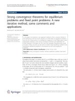
SITE PROJECT ORGANIZATION CHART - BD234 JSC
B
- Qualified personnel be attach.
4.2 Equipment.
Based on estimated volume of work, approximately machine like under tabulation
The number of equipments and machines as follow:
No.
Equipment name
Spec./
capacity
Mobilization plan
1
Dump truck
15 m3
6
2
Excavator, bucket capacity
1,2 m3
2
3
Breaker machine
2 ton
1
4
Water pump
3
15 m /h(110 mm)
4
Page | 6
Rev B
METHOD STATEMENT FOR
TG FOUNDATION & TURBINE BUILDING
5
Bend machine
2,2 KW
4
6
Cutting machine
5 KW
4
7
Welding machine
23 KW
6
8
Vibrator
2,2 KW
16
9
Automatic level
Typical
4
10
Total station
Typical
1
11
High-up truck crane
15 T
1
12
Mobile crane
55T
1
13
Pump car
60m 3/h
03 (01 backup)
14
Mixed truck
6m3
15
15
Water truck
8m3
1
B
• Above table is just initial proposal and actual equipment will be changed depending on site condition
5.0
SURVEY AND SETTING OUT.
Prior to the work commencement, construction drawing will be reviewed to check of its latest issuance for
construction. Layout and survey marking will be marked using surveying equipment (total station, level
machine) having a valid calibration certificate.
The certificate of the total station and automatic level have been calibrated by third party
List of Benchmarks:
Coordinate
Control Point
Elevation Plan
EL + H (m)
X (m)
Y (m)
PBM-1
1379292.588
612280.290
11.681
PBM-2
1378797.938
612634.564
11.617
PBM-3
1379069.245
612383.137
20.319
PBM-4
1379119.110
611464.236
53.598
Page | 7
Rev B
METHOD STATEMENT FOR
TG FOUNDATION & TURBINE BUILDING
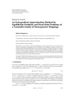
6.0 GENERAL ARRANGEMENT OF TG FOUNDATION
TURBINE GENERATOR UNIT #1
B
Page | 8
Rev B
METHOD STATEMENT FOR
TG FOUNDATION & TURBINE BUILDING
TURBINE GENERATOR UNIT #2
B
Page | 9
Rev B
METHOD STATEMENT FOR
TG FOUNDATION & TURBINE BUILDING
7.0 WORK METHOD
7.1 Sequence excavation and backfilling for TG Foundation & Turbine building Area
B
SEQUENCE OF CONSTRUCTION PLAN UNIT #1
SEQUENCE OF CONSTRUCTION INCLUDES 5 PHASES, 1 PHASE INCLUDING WORK AS FOLLOW:
+ EXCAVATION WORK (EXCAVATION SLOPE OF WEATHERED ROCK IS 1:0,3~1:0,5 DEPENDING ON THE ACTUAL
CONDITION, ACCORDING TO TCVN STANDARD 4054:2005 ITEM 7.7.1)
+ LEAN CONCRETE (SOIL SURFACE PREPARATION, COMPACTION; FDT (IF NECESSARY) & INSPECTION PRIOR TO
LEAN CONCRETE).
+ REBAR, FORMWORK
+ CASTING CONCRETE.
+ CURING CONCRETE & REMOVE FORMWORK
+ BITUMINE PAINTING (REFERENCE ITP VP1-0-L4-C-GEN-10028)
+ BACKFILL. (REFERENCE ITP FOR GENERAL EXCAVATION AND BACKFILLING WORK VP1-0-L4-C-GEN-10012)
(SEQUENCE OF CONSTRUCTION PLAN UNIT #2 SAME AS UNIT # 1)
Page | 10
Rev B
METHOD STATEMENT FOR
TG FOUNDATION & TURBINE BUILDING
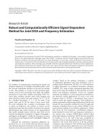
PHASE 01
B
Step 1: Excavate Axis T1 and TA-TE; EL +1.7m to EL+1.1m & axis T8-T9 and TA-TE EL +3.5m to EL +1.9m.
Step 2: Bottom soil/soil surface preparation (removing loose material & compaction) including survey work.
Step 3: Installation of formwork & inspection prior to pour lean concrete.
Step 4: Pouring lean concrete.
Step 5: Survey setting out, installation of rebar & formwork.
Step 6: Installation of concrete level marking & final inspection prior to pouring concrete.
Step 7: Concrete curing & dismantling of formwork.
Step 8: Visual inspection on concrete surface/ defect & repairing work prior to Bitumen painting. (Reference ITP for bitum panting
work VP1-0-L4-C-GEN-10028)
Step 9: Final inspection prior to soil backfilling. (Reference ITP for general excavation and backfilling work VP1-0-L4-C-GEN-10012)
Step 10: Soil backfilling, compaction & FDT (if required).
Page | 11
Rev B
METHOD STATEMENT FOR
TG FOUNDATION & TURBINE BUILDING
PHASE 02
B
Page | 12
Rev B
METHOD STATEMENT FOR
TG FOUNDATION & TURBINE BUILDING
Step 1: Excavation axis T2 and TA-TE, from EL +1.7m to EL -2.15m
Step 2: Bottom soil/soil surface preparation (removing loose material & compaction) including survey work.
Step 3: Installation of formwork & inspection prior to pour lean concrete.
Step 4: Pouring lean concrete.
Step 5: Survey setting out, installation of rebar & formwork.
B
Step 6: Installation of concrete level marking & final inspection prior to pouring concrete.
Step 7: Concrete curing & dismantling of formwork.
Step 8: Visual inspection on concrete surface/ defect & repairing work prior to Bitumen painting. (Reference ITP for bitum panting
work VP1-0-L4-C-GEN-10028)
Step 9: Final inspection prior to soil backfilling. (Reference ITP for general excavation and backfilling work VP1-0-L4-C-GEN-10012)
Step 10: Soil backfilling, compaction & FDT (if required).
Page | 13
Rev B
METHOD STATEMENT FOR
TG FOUNDATION & TURBINE BUILDING
PHASE 03
B
Phase 03.1
Step 1: Excavation TG Foundation EL +1.7m to EL -2.15m (Axis T3-T7 and TA-TE)
Step 2: Bottom soil/soil surface preparation (removing loose material & compaction) including survey work.
Step 3: Installation of formwork & inspection prior to pour lean concrete.
Step 4: Pouring lean concrete.
Step 5: Survey setting out, installation of rebar & formwork.
Step 6: Installation of concrete level marking & final inspection prior to pouring concrete.
Step 7: Concrete curing & dismantling of formwork.
Step 8: Visual inspection on concrete surface/ defect & repairing work prior to Bitumen painting. (Reference ITP for bitum panting
work VP1-0-L4-C-GEN-10028)
Step 9: Final inspection prior to soil backfilling. (Reference ITP for general excavation and backfilling work VP1-0-L4-C-GEN-10012)
Step 10: Soil backfilling, compaction & FDT (if required).
Page | 14
Rev B
METHOD STATEMENT FOR
TG FOUNDATION & TURBINE BUILDING
B
Phase 03.2
Step 1: Excavation for CEP EL+1.7m to EL -6.4m (Axis T4-T6 and TE)
Step 2: Bottom soil/soil surface preparation (removing loose material & compaction) including survey work.
Step 3: Installation of formwork & inspection prior to pour lean concrete.
Step 4: Pouring lean concrete.
Step 5: Survey setting out, installation of rebar & formwork.
Step 6: Installation of concrete level marking & final inspection prior to pouring concrete.
Step 7: Concrete curing & dismantling of formwork.
Step 8: Visual inspection on concrete surface/ defect & repairing work prior to Bitumen painting. (Reference ITP for bitum
panting work VP1-0-L4-C-GEN-10028)
Step 9: Final inspection prior to soil backfilling.(Reference ITP for general excavation and backfilling work VP1-0-L4-C-GEN-10012)
Step 10: Soil backfilling, compaction & FDT (if required).
Page | 15
Rev B
METHOD STATEMENT FOR
TG FOUNDATION & TURBINE BUILDING
B
Page | 16
Rev B
METHOD STATEMENT FOR
TG FOUNDATION & TURBINE BUILDING
PHASE 04
B
Step 1: Excavation for foundation Axis T6-T8 and TA-TB from EL+3.6m to EL+3.15m
Step 2: Bottom soil/soil surface preparation (removing loose material & compaction) including survey work.
Step 3: Installation of formwork & inspection prior to pour lean concrete.
Step 4: Pouring lean concrete.
Step 5: Survey setting out, installation of rebar & formwork.
Step 6: Installation of concrete level marking & final inspection prior to pouring concrete.
Step 7: Concrete curing & dismantling of formwork.
Step 8: Visual inspection on concrete surface/ defect & repairing work prior to Bitumen painting. (Reference ITP for bitum
panting work VP1-0-L4-C-GEN-10028)
Step 9: Final inspection prior to soil backfilling.(Reference ITP for general excavation and backfilling work VP1-0-L4-C-GEN-10012)
Step 10: Soil backfilling, compaction & FDT (if required).
Page | 17
Rev B
METHOD STATEMENT FOR
TG FOUNDATION & TURBINE BUILDING
PHASE 05
B
Step 1: Excavation for foundation Axis T1-T11 and TE-CA , axis T10-T11 and TA-TE from EL+3.600 to EL+1.900;
EL+4.700 to EL+1.9m; EL+2.3m to EL+1.75m
Step 2: Bottom soil/soil surface preparation (removing loose material & compaction) including survey work.
Step 3: Installation of formwork & inspection prior to pour lean concrete.
Step 4: Pouring lean concrete.
Step 5: Survey setting out, installation of rebar & formwork.
Step 6: Installation of concrete level marking & final inspection prior to pouring concrete.
Page | 18
Rev B
METHOD STATEMENT FOR
TG FOUNDATION & TURBINE BUILDING
Step 7: Concrete curing & dismantling of formwork.
Step 8: Visual inspection on concrete surface/ defect & repairing work prior to Bitumen painting. (Reference ITP for bitum
B
panting work VP1-0-L4-C-GEN-10028)
Step 9: Final inspection prior to soil backfilling.(Reference ITP for general excavation and backfilling work VP1-0-L4-C-GEN-10012)
Step 10: Soil backfilling, compaction & FDT (if required).
Page | 19
Rev B