METHOD STATEMENT FOR CONSTRUCTION OF CW INTAKE PUMP STATION
Bạn đang xem bản rút gọn của tài liệu. Xem và tải ngay bản đầy đủ của tài liệu tại đây (17.38 MB, 138 trang )
Comment Response Sheet (CRS)
Project Title
Van Phong 1 BOT Thermal Power Plant Project
Document Title
METHOD STATEMENT FOR CONSTRUCTION OF
CW INTAKE PUMP STATION
Document Type
For Approval
Document No
VP1-0-L4-C-UPC-10048
Returned Status
NA
Prepared by
CRS No
VP1-0-L4-C-UPC-10048-B-CRS
CRS Issued Date
16/06/2020
Engineer
Construction
Review
Date
Status O/C *
Remarks
25/05/2020
O
16/06/2020
C
No.
1
2
3
Section/
Page
1
3
3
Owner’s Comment
Response to Comment
The following MS is very rough and poor contents
from considering the huge size of structure and
Deepest excavation
DHI should review & check sufficiently before
submission of MS.
Noted. DHI updated on Rev.B.
Include the attachments in the main file rather
than attached files.
DHI listed separately to provide more detail and
specific information.
25/05/2020
O
16/06/2020
C
25/05/2020
(1) temperature control: numbering the
thermocouples and monitor the temperature in
principle that first casting first monitoring.
(2) Regarding concrete volume of pump house
foundation greater than 1000m3, calculation of
pump trucks before casting should be attached.
(3) Construction time schedule to be attached for
information.
(4) Access path in emergency case should be
considered due to deep foundation posing high
risk on safety.
25/06/2020
25/05/2020
O
(1) There are 5 thermocouples which are
arranged with numbering monitor the
temperature easier (section 6.5.7)
16/06/2020
O
Lot 4
(2) Calculation of concrete supply is attached as
Attachment #4
(3) Construction schedule is attached as
Attachment #7
(4) Noted, access ways will be prepared at 3
sides of foundation.
Page 1 of 11
Comment Response Sheet (CRS)
4
5
6
7
8
9
10
11
12
4
4
4
5
5
7
8
8
8
Outline of Structure and Works
> Size of structure
> Depth of Excavation and Volume
> Total Concrete Volume and so on.
DHI updated on Rev.B.
25/05/2020
O
16/06/2020
C
Why there is no HSE procedures such as lifting
procedure, scaffolding management procedure,
mobile plant operation, etc?
DHI updated on Rev.B.
25/05/2020
O
16/06/2020
C
Plan & Sections which show size of structure and
thickness of all members.
These drawings should be shown.
DHI updated on Rev.B.
25/05/2020
O
16/06/2020
C
Are there any design for the foundation of the
tower crane?
Tower Crane Foundation design is attached as
Attachment #6.
25/05/2020
O
16/06/2020
C
Capacity of pump and calculation of dewatering
system should be provided
The calculation sheet for dewatering system is
attached as Attachment #3
25/05/2020
O
16/06/2020
C
The bottom of base slab is 11m under ground
water. Dewatering
system is big issue and should be stated and
calculation needed.
The calculation sheet for dewatering system is
attached as Attachment #3.
25/05/2020
O
16/06/2020
C
There is no berm on this slope.
Slope stability check needed.
It is part of CW Intake Canal. And slope stability
of this area will be checked on “CW Intake Canal
Drawing”.
25/05/2020
O
16/06/2020
C
How much degree of this access way ?
There are 2 access ways as “6.1 Excavation”.
25/05/2020
O
16/06/2020
C
25/05/2020
O
16/06/2020
C
The slopes and the fence along the access way
are different from other drawings in this document.
Use only one (correct) plan.
DHI updated on Rev.B.
Page 2 of 11
Comment Response Sheet (CRS)
13
14
15
9
9
9
Actual GWL may be EL +0.6~1m, and then dewatering method and detail should be stated for
completely drying up at the bottom of excavation
before lean concrete.
Especially calculation of de-watering shall be
needed.
Excavation should be considered of heavy rain.
At another project, all construction equipments
were under water by night time rain.
DHI will carry out dewatering after meet
underground water during Pre-Excavation up to
EL+0.0m
Volume of excavation at each step should be
shown including access way.
DHI updated on Rev.B.
25/05/2020
Please describe disposal area for this excavation
quantity?
Excavated soil will be transported based on site
condition, used for landfill work.
25/05/2020
O
16/06/2020
C
25/05/2020
O
16/06/2020
C
25/05/2020
O
16/06/2020
C
The calculation sheet for dewatering system is
attached as Attachment #3.
16/06/2020
Closed
Excavated soil shall be handle by EPC within site,
disposal outside is not acceptable so far.
16
9
25/05/2020
This width maybe too narrow for dewatering
method of GWL and
disposal of heavy rain during pouring concrete of
base slab.
16/06/2020
Closed
Mean concreting work will not be allowed in bad
weather.
Closed
DHI updated on Rev.B following “VP1-0-L4-CUPC-10501 CW INTAKE PUMP STATION,
EXCAVATION DRAWING”.
Before casting concrete, DHI will check weather
forecast to prevent heavy rain during concrete
work. The concreting work should avoid the rainy
day.
25/05/2020
O
16/06/2020
C
Closed
Page 3 of 11
Comment Response Sheet (CRS)
17
18
9
9
Please provide where is section A, section C on
the plan drawing?
DHI updated on Rev.B.
25/05/2020
O
16/06/2020
C
25/05/2020
Address dewatering of the excavation pit.
Consider water inflow from ground water and rain
surface water.
The calculation sheet for dewatering system is
attached as Attachment #3. DHI also updated the
Attachment #3
25/05/2020
O
16/06/2020
C
Thickness of Lean Con’c shall be followed
Construction Drawing.
25/05/2020
O
16/06/2020
O
16/06/2020
Closed. This item is closed, but additional
comments on the topic are made in the report.
19
10
25/05/2020
For wide area (32m x 44m) thickness of lean
concrete 50mm is too thin, because tolerance of
excavation should be less than ± 20mm and the
thickness of base slab may be 2m.Ðean concrete
should have enough strength for reinforcement
and form work.
16/06/2020
OPEN
If lean concrete thickness follow construction
drawing, please delete 50mm on page 9.
Further more, lean concrete shall be strong
enough to bear the load of rebar case and weight
enough to avoid the push up of GWL after
dewatering.
Minimum 10cm is recommended.
20
10
The direction of this slope does not match the 3D
view and does not seem correct.
25/06/2020
DHI has updated on MS rev C and DHI will
comply with construction drawing and project
specification.
DHI updated on Rev.B.
Closed
25/05/2020
O
16/06/2020
C
Page 4 of 11
Comment Response Sheet (CRS)
21
22
23
24
25
26
27
28
29
11
13
13
13
13
13
14
14
15
Please describe interface with Lot-3 where has
CW pipe?
DHI updated on Rev.B.
25/05/2020
O
The detail and describe interface with Lot-3 is
added following Drawing.
16/06/2020
C
- How much volume of concrete ? How long for
pouring concrete by 3 concrete pump trucks ?
- The detail method of pouring concrete should be
stated in considering with rainy season.
The volume of base slab is 1839m3, and it will
take around 16 hours to cast concrete.
25/05/2020
O
16/06/2020
C
The construction equipment and storage area are
very close to the edge of the slope. Confirm that
this has been considered in the stability
calculations.
The equipment and storage area will be arranged
at least 2m, away from the edge of slope to
prevent slope collapsing.
25/05/2020
O
16/06/2020
C
Formwork frame is different with the description in
next page (14). Attached calculation is not
provided for this frame
DHI updated on Rev.B and Attachment #1.
25/05/2020
O
16/06/2020
C
The lengths of the support members do not match
the excavation dimenesions
DHI updated on Rev.B.
25/05/2020
O
16/06/2020
C
This slope does not match the excavation slopes.
DHI updated on Rev.B.
25/05/2020
O
16/06/2020
C
DHI updated on Rev.B and it is calculated with
considering safety factor.
25/05/2020
O
16/06/2020
C
Concrete volume for each stage of wall should be
shown.
The concrete volume of each stage is attached
as Appendix #7.
25/05/2020
O
16/06/2020
C
Is it correct with attached calculation?
It is calculated with considering safety factor.
25/05/2020
O
16/06/2020
C
Is it correct with attached calculation?
The calculation of casting massive concrete is
attached as Attachment #4.
Page 5 of 11
Comment Response Sheet (CRS)
30
15
No calculation for this.
DHI updated on Rev.B and it is calculated with
considering safety factor.
25/05/2020
O
16/06/2020
C
25/05/2020
O
Before casting concrete, DHI will check weather
forecast to prevent heavy rain during concrete
work. The concreting work should avoid the rainy
day.
16/06/2020
C
The calculation sheet for support system is
attached as Attachment #1.
25/05/2020
O
16/06/2020
C
The volume of concrete is 788m3.
31
16
25/05/2020
How much volume of concrete for top slab ?
How prevent pouring concrete of slab from rain ?
16/06/2020
Closed
Mean concreting work will not be allowed in bad
weather.
32
16
25/05/2020
- Design/calculation for support is necessary,
please provide properly.
- Load test for testing bearing capacity and
deflection of scaffolding is recommended.
Closed
16/06/2020
Noted,
Calculation of support is attached as appendix 1.
However, the reply in CRS is not correct.
33
17
What construction method is applied for this slab
?
Closed
DHI updated on Rev.B.
25/05/2020
O
DHI will backfill up to EL -0.7m and carry out
bottom concrete.
16/06/2020
C
Page 6 of 11
Comment Response Sheet (CRS)
34
35
18
20
For base slab (32m x 43m), plastic sheet is not
enough for sudden rain. Temporary tent is
recommended and can be continue pouring
concrete at rain. If temporary tent used for base
slab, heavy rain on Tent should be
gathered and dewatered by enough pumps.
If heavy rain flow into fresh concrete, all poured
concrete shall be removed.
DHI updated on Rev.B.
25/05/2020
O
16/06/2020
C
General comment:
(i) Mass concrete center temperature shell not
exceed 70 oC as required in Technical
specification. (ii) Mock-up for massive concrete is
required.
(iii) Temperature calculation for massive concrete
is required to submit.
(i) The monitoring of temperature will be carried
out by the thermocouple.
25/05/2020
O
16/06/2020
C
The method of repair concrete surface and
applied Bituminous Waterproofing is submitted
separately, “VP1-0-L4-C-GEN-10027 METHOD
STATEMENT FOR WATER PROOFING OF
UNDERGROUND CONCRETE STRUCTURES”
25/05/2020
O
16/06/2020
C
K=95% is required for compaction density
following “VP1-0-L4-C-UPC-10501 CW INTAKE
PUMP STATION, EXCAVATION DRAWING”.
25/05/2020
O
16/06/2020
C
(ii) The Mock-up of massive concrete has been
conducted with Pre-Cast Concrete for Temporary
Unloading Ramp and result was submitted “VP10-L4-Q-GEN-10047 Proposal of Concrete Mix
Proportion for Mass Concrete”.
(iii) DHI updated on Rev.C. This information will
be submitted via ‘VP1-0-L4-Q-GEN-10047
Proposal of concrete mix for mass concrete
(Rev.B)
36
37
20
21
Bituminous painting also stated in this section.
Compaction density should be stated.
Page 7 of 11
Comment Response Sheet (CRS)
38
39
21
21
Backfilling for another section should be shown.
During backfilling, buoyancy check by GWL
should be stated.
DHI updated backfilling section on Rev.B.
25/05/2020
O
Buoyancy during construction period is
considered “VP1-0-L4-C-UPC-10001 CW Intake
Pump Station Calculation”.
16/06/2020
C
25/05/2020
1. Please prepare the risk assessment "RA" and
job safety analysis "JSA" in response to EPC risk
assessment procedure and Vietnamese
regulation. RA and JSA should be submitted
pertaining to Method statement.
2. The RA and JSA should be prepared based on
the procedure and sequence section in this
document cum tower crane installation. it is
submitted pertaining to
25/06/2020
25/05/2020
O
DHI has updated on MS rev C (see attachment
6).
16/06/2020
O
OPEN
There is only risk assessment for tower crane.
Doosan risk assessment procedure said that a risk
assessment which cover all the task mentioned in this
method statement shall be prepared based on sequence
of construction work and the JSA is only prepared for the
residual risk higher than 6.
It seem no Doosan HSSE team's review on this document
16/06/2020
OPEN. There is only JSA for tower crane
installation, what about risk assessment to cover
all the task, JSA for high residual risk based on
Doosan risk assessment procedure?
40
41
4
8
16/06/2020
QC engineers included ?
25/06/2020
16/06/2020
Periodical monitoring of stability of slope and
seepage of GW should be executed.
25/06/2020
16/06/2020
Closed
O
16/06/2020
Closed
O
DHI has revised and updated on MS rev C
(section 3)
DHI has revised and updated on MS rev C
(section 6.1)
Page 8 of 11
Comment Response Sheet (CRS)
42
43
44
45
46
10
10
21
26
#Attachment 3
Page 1/3
47
#Attachment 3
Page 1/3
48
#Attachment 3
Page 1/3
16/06/2020
Is this access way for only 1st excavation?
25/06/2020
16/06/2020
This slope and stability check will be stated at
work of Intake canal.
25/06/2020
16/06/2020
From the construction schedule, pouring concrete
of base slab will be just in rainy season. Is this
plastic cover over the full size of base slab ( 45m
x 30m) ?
25/06/2020
16/06/2020
This is also Rev. B ?
25/06/2020
16/06/2020
Show the location with actual size on the
excavation plan.
25/06/2020
16/06/2020
This is not possible at the bottom of the pit with
the current layout
25/06/2020
16/06/2020
Where is this taken from?
25/06/2020
16/06/2020
Closed
O
16/06/2020
Closed
O
16/06/2020
Closed
O
16/06/2020
Closed
O
16/06/2020
O
No, 1st excavation mean level of this access way
is same with level of 1st excavation layer
Yes, this slope and stability check will be stated
at work of Intake canal
Yes, material will be prepared full size of
structure
Yes, it was rev B also
DHI has revised and updated on Rev.C(section
6)
Closed
16/06/2020
Closed
DHI has deleted this information and updated on
Rev.C (attachment 4)
Refer to soil investigation report, take from
borehole BH42, calculate the amount of water
that penetrates to the foundation pit with high
water level: +0.07m
O
16/06/2020
O
Closed
Page 9 of 11
Comment Response Sheet (CRS)
49
#Attachment 3
Page 2/3
50
#Attachment 3
Page 3/3
51
#Attachment 3
Page 3/3
52
#Attachment 5
16/06/2020
Heavy rainfall and inflow from ramp and
surrounding areas (within the protection dike)
need to be considered.
25/06/2020
16/06/2020
This drawing does not match what is described 2
poages earlier.
25/06/2020
16/06/2020
Predicted GWL after dewatering at pump sump.Út
center, GWL should be lowered to 0.5m under
excavated bottom.
25/06/2020
How is this base of tower crane disposed
25/06/2020
completion of CW Pump Station ?
53
#Attachment 8
Page 1
16/06/2020
Indicate which code is used and show clear
reference for the formulaes.
16/06/2020
O
Closed
Noted, the calculation is included the rainfall from
surrounding areas.
16/06/2020
O
Closed
DHI has revised and updated on
Rev.C(attachment 4)
16/06/2020
Closed
O
16/06/2020
Closed
O
16/06/2020
O
Noted, the pump will be operated regularly to
ensure GWL should be lowered to 0.5m under
excavated bottom
We design it become part of intake canal
structure, intake canal yard is designed by rubble
stone concrete.
25/06/2020
DHI has deleted this attachment. Relation work
will be combined with section 6.5.6 and
document “VP1-0-L4-Q-GEN-10047 Prop of
Concrete Mix Proportion Mass Concrete “ which
will be submitted in separately
Closed
Page 10 of 11
Comment Response Sheet (CRS)
54
#Attachment 8
Page 2
55
#Attachment 8
Page 2
16/06/2020
Check Column headings
16/06/2020
Attachment 3 deals with the dewatering.
16/06/2020
Since Q=weight*C and W= Weight*C*30.1, it is
Page 2
obvious that the result is 30.1.Ðecheck and make
a correct calculation:ßor each ingredient the
predicted temperature just before concreting
needs to be used, not the local average air
temperature. Cement stored in silos will be much
hotter in sunny weather, same goes for coarse
and fine aggregates; the water is likely to be
cooler and can correct the concrete temperature
downwards.
Additional Notes (if any)
* O - Open, C – Closed
56
#Attachment 8
25/06/2020
DHI has deleted this attachment. Relation work
will be combined with section 6.5.6 and
document “VP1-0-L4-Q-GEN-10047 Prop of
Concrete Mix Proportion Mass Concrete “ which
will be submitted in separately
25/06/2020
DHI has deleted this attachment. Relation work
will be combined with section 6.5.6 and
document “VP1-0-L4-Q-GEN-10047 Prop of
Concrete Mix Proportion Mass Concrete “ which
will be submitted in separately
25/06/2020
16/06/2020
O
Closed
16/06/2020
O
Closed
16/06/2020
O
DHI has deleted this attachment. Relation work
will be combined with section 6.5.6 and
document “VP1-0-L4-Q-GEN-10047 Prop of
Concrete Mix Proportion Mass Concrete “ which
will be submitted in separately
Closed
Page 11 of 11
AP
APPROVED
Approved
AC
APPROVED WITH COMMENT
Contractor to revise the correction and resubmit
NA
NOT APPROVED
Revise the correction and resubmit before proceeding
REVIEWED
RE
REVIEWED WITH COMMENT
RC
ForInformation
Approval
acknowledged with no comment
Information acknowledged with comments
Note: Approval or comment does not relieve the Contractor of
all obligations covered under contract
Discipline: Civil
07 Jul 20
Date:
C
25-Jun-2020
For Approval
J.H CHOI
K.S KIM
J.G KIM
B
04-Jun-2020
For Approval
J.H CHOI
K.S KIM
J.G KIM
A
12-May-2020
For Approval
J.H CHOI
K.S KIM
J.G KIM
REV
DATE
DESCRIPTION
Approved
Checked
Prepared
OWNER
VAN PHONG POWER COMPANY LIMITED
PROJECT
Van Phong 1 BOT Thermal Power Plant Project
Status
□Approved
□Approved with Comment
□Not Approved
□Reviewed
OWNER’S ENGINEER
Pöyry Switzerland Ltd.
EPC CONTRACTORS
IHI–TESSC–CTCI–DHI CONSORTIUM
PROJECT DOCUMENT No
REV
VP1-0-L4-C-UPC-10048
C
DOCUMENT TITLE
METHOD STATEMENT FOR CONSTRUCTION OF CW INTAKE PUMP STATION
EPC
EPC DOCUMENT No.
VP1-0-L4-C-UPC-10048
Doosan Heavy Industries and Construction
1| Page
REV
C
VAN PHONG 1 BOT THERMAL POWER PLANT PROJECT
Table of Contents
1.
PREFACE.................................................................................................................................... - 3 -
2.
REFERENCE ............................................................................................................................... - 3 -
3.
MANPOWER & EQUIPMENT ............................................................................................... - 4 -
4.
RESPONSIBILITIES AND ORGANIZATION........................................................................ - 5 -
5.
PROCEDURE AND SEQUENCE ............................................................................................. - 7 -
6.
CONSTRUCTION WORK ....................................................................................................... - 7 6.1 Excavation ............................................................................................................................ - 8 6.2 Reinforcement work .......................................................................................................... - 9 6.3 Installation of Embedded plate, box out, cable entry ducts (If any) .................... - 10 6.4 Form work .......................................................................................................................... - 11 6.5 Concrete work ................................................................................................................... - 12 6.5.1
Lean concrete..................................................................................................................................- 12 -
6.5.2
Base slab............................................................................................................................................- 12 -
6.5.3
Wall slab ............................................................................................................................................- 14 -
6.5.4
Slab .......................................................................................................................................................- 15 -
6.5.5
6.6.4 Construction Joint ............................................................................................................- 17 -
6.5.6
Pouring concrete...........................................................................................................................- 18 -
6.5.7
Curing and Temperature Control for Mass concrete (bottom slab only) .....- 19 -
6.6 Backfilling work ................................................................................................................ - 21 7. INSPECTION AND TESTING ............................................................................................................ - 22 8. ENVIRONMENT, HEALTH AND SAFETY (EHS)........................................................................... - 22 8.1 Risk assessment and Job Safety Analysis ................................................................... - 22 9. ATTACHMENT ................................................................................................................................... - 57 Attachment #1 Calculation sheet for Form work ............................................................. - 58 Attachment #2 Method drawing ......................................................................................... - 59 Attachment #3 Calculation sheet for water pump of dewatering-Pump station ..... - 60 Attachment #4 Calculation sheet for concrete supply of massive concrete .............. - 61 Attachment #5 The design for foundation of Tower crane........................................... - 62 Attachment #6 JSA for Tower crane................................................................................... - 63 Attachment #7 Schedule of Pump station ........................................................................ - 64 - 2 - | Page
Rev: C
VAN PHONG 1 BOT THERMAL POWER PLANT PROJECT
1.
PREFACE
The purpose of this method is to describe the methodology involved in construction work for the
CW Intake Pump station item and to detail out the steps to be taken in order to meet the technical
requirements of VP1 BOT Thermal Power Plant.
2.
Project
Van Phong 1 BOT Thermal Power Plant
Company/Owner
Van Phong Power company limited (VPCL)
Contractor
DHI
ITEM
CW Intake Pump station
Dimension (B x L x H)
29m x 41.035m x 15.74m
Quantity (Excavation /Concrete)
54,927m3 / 7,694m3
REFERENCE
2.1 Applicable Code and Standard
• ACI 347-Guide to formwork for concrete
• ACI 304-Guide for measuring, mixing, transporting, and placing concrete
• ACI 301-Specifications for structural concrete for buildings.
• ACI 318-Building Code Requirements for Structural Concrete.
• ACI-305R-Guide to hot weather concreting.
• ASTM C33: Standard specification for concrete aggregate
• ASTM C94: Standard specification for Ready-mix concrete
• ASTM C150: Standard specification for Portland cement
• ASTM C494: Standard specification for Chemical admixture for Concrete.
• Part III-2 Exhibit B1 Tech Spec Section 8.
• Part III-2 Exhibit B1 Attachment G Civil/Structure Technical Guideline.
• VP1-0-EPC-H-GEN-10511-Health, Safety and Environment Plan
• VP1-C-L4-H-GEN-00003- HSE Risk Management
• VP1-C-L4-H-GEN-00005- HSE accident and incident
• VP1-C-L4-H-GEN-00009- Working at height
• VP1-C-L4-H-GEN-00012- Lifting operations
• VP1-C-L4-H-GEN-00020- Scaffolding
• VP1-C-L4-H-GEN-00024- Hot work
• VP1-C-L4-H-GEN-00026- Excavation
• VP1-C-L4-H-GEN-00027- Permit to work
- 3 - | Page
Rev: C
VAN PHONG 1 BOT THERMAL POWER PLANT PROJECT
2.2 Drawing and Method Statement
• VP1-0-L4-C-GEN-10007 Method statement for General concrete work
• VP1-0-L4-C-GEN-10008 Method statement for Excavation and backfilling work
• VP1-0-L4-C-GEN-10027 Method statement for Waterproofing for Underground concrete structure
• VP1-0-L3-P-GEN-04015 General Arrangement Drawing for Circulating Water Pump Station and
Desalination System Area
• VP1-0-L3-P-GEN-04016 General Arrangement Drawing for Circulating Water Pump Station and
Desalination System Area (Section)
• VP1-0-L3-G-PAA-00024 General Arrangement Drawings for Intake Facility System
• VP1-0-L4-C-UPC-10501 CW Intake Pump Station, Excavation Drawing
• VP1-0-L4-C-UPC-10101 CW INTAKE PUMP STATION, PLAN DRAWING
• VP1-0-L4-C-UPC-10102 CW INTAKE PUMP STATION, SECTION DRAWING
• VP1-0-L4-C-UPC-10103 CW INTAKE PUMP STATION, DETAIL DRAWING
• VP1-0-L4-C-UPC-10301 CW INTAKE PUMP STATION, REINFORCEMENT DRAWING
3.
MANPOWER & EQUIPMENT
• Manpower mobilized for construction of the Boiler are listed as followings:
No.
C
Position
Quantity
1
Site Manager
01
2
Site engineer
03
3
QA/QC engineer
01
4
Safety supervisor
01
5
Surveyor
02
6
Crane operator
02
7
Roller operator
01
8
Worker
60
• Equipment mobilized for construction of the Boiler are listed as followings:
No.
Equipment
Unit
Quantity
1
Total station
nos
02
2
Auto level
nos
02
3
Tower Crane
nos
01
- 4 - | Page
Remark
Rev: C
VAN PHONG 1 BOT THERMAL POWER PLANT PROJECT
4
Truck crane
nos
01
5
Excavator
nos
03
6
Roller
nos
02
7
Rammer
nos
02
8
Plate compactor
nos
02
9
Cutting machine
nos
02
10
Bending machine
nos
02
11
Welding machine
nos
10
12
Concrete pump truck
nos
03
13
Concrete mixer truck
nos
12
14
Concrete vibrator
nos
12
15
Water pump
nos
05
16
Troweling machine
nos
-
17
Light
nos
20
4. RESPONSIBILITIES and ORGANIZATION
• It is overall responsibility of Site Manager to organize resources prior to perform construction
activities as per project specification in compliance with the quality, schedule & safety requirements.
• EHS Manager will ensure in coordination with Site Engineer that all measure/construction taken
shall be maintained till completion of job.
• It is the responsibility of Construction Manager/Site Engineer that construction activities are
executed according to the relevant project specification in compliance with the quality, schedule &
safety requirements.
• Contractor will ensure that all works are performed safely according to the attachment.
• The relevant Contractor Supervisor will ensure that the work is carried out in accordance with this
method statement and project specification.
• The QC Inspector will ensure that the work is executed according to the requirements of quality
dossier are fulfilled.
- 5 - | Page
Rev: C
VAN PHONG 1 BOT THERMAL POWER PLANT PROJECT
EPC CONTRACTOR – DHI
Civil Manager
QC Manager
Safety Manager
DHI-Civil Site Engineer
DHI-Civil QC Engineer
EHS Safety Supervisor
Local Sub-contractor:
CONSTRUCTION CORPORATION NO.1 - JSC
Site Manager
QC Manager
EHS Manager
Site Supervisor
QC Supervisor
Safety Supervisor
Workers
- 6 - | Page
Rev: C
VAN PHONG 1 BOT THERMAL POWER PLANT PROJECT
5. PROCEDURE AND SEQUENCE
C
6. CONSTRUCTION WORK
• Reference Method statement: “VP1-0-L4-C-GEN-10007 Method statement for General concrete
work” and “VP1-0-L4-C-GEN-10008 Method statement for Excavation and backfilling work” for
requirement and describe of Excavation, backfilling and concrete work.
• This method statement is for Procedure and Sequence for Execution Pump station only.
- 7 - | Page
Rev: C
VAN PHONG 1 BOT THERMAL POWER PLANT PROJECT
General Plan
C
6.1 Excavation
C
• The dry soil will be used for backfilling within the site based on actual condition, wet soil will be
C
used to filling at landfill area and mud will be move out to disposal area.
• Before start excavate work, Dike, hard barricade system at EL: +5.6 surround pit shall be made.
- 8 - | Page
Rev: C
VAN PHONG 1 BOT THERMAL POWER PLANT PROJECT
C
• The clearance between the edge of foundation to bottom of slope (1.5m) will be complied with the
submitted drawing.
• The calculation for drainage of pump will be attached as an attachment.
• The state of slope should be checked for stable before install ladder and during working time.
6.2 Reinforcement work
• Steel bars shall be stored on the site on racks or supports of enough height to keep the bars clear
of the ground and steel bar shall be covered by plastic sheet in order to prevent corrosion by the
sea environment.
• Bar bending schedule shall be submitted before commencement of work.
• Fabricating, installing foundation rebar comply with the approved design, project specification, ACI
117 and ACI 318, approved BBS. Lap splicing method shall be used for rebar connection, the lap
length shall comply with the approved design drawing and applied standard.
• Any kind of hot cutting and bending rebar shall not be allowed.
• Fabricated rebar will be transported from the workshop to construction site by lorry crane.
• Rebar shall be erected such as to form a rigid cage within the formwork, with every intersection
being bound together with appropriate binding wire.
- 9 - | Page
Rev: C
VAN PHONG 1 BOT THERMAL POWER PLANT PROJECT
• Rebar chairs of an approved diameter and spacing shall be provided between layers of reinforcement
where necessary to maintain the required positions. The calculation of rebar chairs will be attached
for review and get approval.
• Specified concrete cover shall be maintained using precast concrete spacer blocks of the same grade
as the concrete in which they are to be used.
• Black annealed steel binding wire of 1mm thickness shall be used for fixing the reinforcing bars. The
binding wire will be double folded to ensure the firmness of the connection.
• Concrete spacer shall be made by same grade concrete as structural grade.
• In practicable, the subcontractor could use extra method such as steel tube frame, cables,
turnbuckles… to keep the rebar stable before carrying out the next steps.
• Inspection of rebar installation shall be conformed to design drawing and approved method
statement, such as grid space, lap length, elevation…
6.3 Installation of Embedded plate, box out, cable entry ducts (If any)
• Inserts are fixed in a position in accordance with the drawings and checked for its line and level.
• The position and levels of embedded plate, box out and cable entry ducts are thoroughly checked
by the Site Engineer and then the inserts are welded to the reinforcement to prevent any movement
during the concreting works. Adequate supports are given to the inserts to avoid any lateral/vertical
movements. Care shall be taken to ensure that no shuttering props are in direct contact with the
inserts.
- 10 - | P a g e
Rev: C
VAN PHONG 1 BOT THERMAL POWER PLANT PROJECT
Regarding CW pipe, after finishing the pipe installation as the detail by the LOT3 and handover to
LOT4, installation of rebar, formwork and cast concrete will be proceeded.
Installation of box out
Installation of cable entry ducts
6.4 Form work
•
Forms shall be made of steel or heavy waterproof plywood. Forms shall conform to the shapes,
lines and dimensions of the structure according to the drawings. It shall be substantial, rigid and
unyielding.
- 11 - | P a g e
Rev: C
VAN PHONG 1 BOT THERMAL POWER PLANT PROJECT
•
Forms shall be so designed, ties and supported so that they will not deflect or bulge during
placement and compaction of the concrete. It shall be sufficiently tight to prevent loss of mortar.
•
Forms for successive lifts on adjacent parts of the structure shall be so arranged that a continuous,
uniform and harmonious texture of concrete surface results.
•
Fabricated forms will be erected on 3 sides and adequately supported using steel props and
bolts/clamps.
•
The vertically, line and levels of the erected forms shall be checked by the formworks Foreman first
instance and subsequently by the Site Engineer and Surveyor.
•
The last side of forms will be erected after the completion on fixing of all inserts and cleaning.
•
Formwork shall be strong enough to withstand, without distortion, all pressures resulting from
placing and vibration of concrete and shall be rigidly and accurately fixed in position.
•
Formwork shall be securely fastened to prevent loss of mortar and surfaces in contact with concrete
shall be uniformly smooth and true with no local defects.
•
The formwork for Intake Pump Station is combined by steel form and plywood form. The design
has considered the rebar arrangement and safe working access during the assembly and
dismantling. The height of formwork is 3m.
•
The capacity of form and frame system are calculated following the attachments.
•
The formwork will be assembled panel by panel, lifted by crane into position. Different panel is
connected to each other by tie rod and bolts and fixed in vertical position by supporting and cable
system.
•
Tolerance: ±6mm for dimension, ±12mm per 1.5m length
6.5 Concrete work
•
Reference Method statement: “VP1-0-L4-C-GEN-10007_ Method statement for General concrete
work” for requirement and describe of concrete work.
6.5.1
Lean concrete
• Subgrade of foundation must be well compacted as requirement unless surface is rock and cleaned
up to ensure the quality of lean concrete. Any marshy ground position must be removed and
compacted by good material.
C
• Lean concrete thickness will be complied with the design drawing. After cast concrete, curing time
is required to get enough strength of concrete before carry out the next activities.
6.5.2
Base slab
• Base slab shall be pouring concrete with one time. The calculation of concrete supply will be
depicting into an attachment.
- 12 - | P a g e
Rev: C
VAN PHONG 1 BOT THERMAL POWER PLANT PROJECT
C
1
2
2
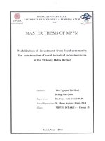
PLAN FORMWORK FOR BASE SLAB
1
• Plan of Formwork for base slab
1500
• Typical of formwork panel. Space of pipe support, tie rod is 800mm.
- 13 - | P a g e
Rev: C
VAN PHONG 1 BOT THERMAL POWER PLANT PROJECT
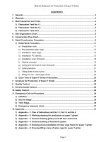
1
300
300
300
300
300
300
320
450
250
320
2
2
400
600
PLYWOOD
18MM
2440
1
SECTION 1-1
800
800
800
800
800
PIPE SUPPORT Ø
D49
SECTION 2-2
6.5.3
Wall slab
• Wall shall be pouring concrete with 5 times, maximum height is 3m.
• Contractor will prioritize the execute for outside wall first. After casting concrete of two phase for
outside wall and inside wall will be followed.
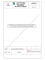
•
Typical of formwork panel. Space of tie rod is 800mm.
- 14 - | P a g e
Rev: C