Báo cáo hóa học: " Research Article Robust Watermarking Scheme Using Wave Atoms" pptx
Bạn đang xem bản rút gọn của tài liệu. Xem và tải ngay bản đầy đủ của tài liệu tại đây (10.83 MB, 9 trang )
Hindawi Publishing Corporation
EURASIP Journal on Advances in Signal Processing
Volume 2011, Article ID 184817, 9 pages
doi:10.1155/2011/184817
Research Article
Robust Watermarking Scheme Using Wave Atoms
H. Y. Leung and L. M. Cheng
Department of Electronic Engineering, City University of Hong Kong, Kowloon, Hong Kong
Correspondence should be addressed to H. Y. Leung,
Received 8 July 2010; Accepted 17 September 2010
Academic Editor: Dennis Deng
Copyright © 2011 H. Y. Leung and L. M. Cheng. This is an open access article distributed under the Creative Commons
Attribution License, which permits unrestricted use, distribution, and reproduction in any medium, provided the original work is
properly cited.
A robust blind watermarking scheme using wave atoms is proposed. The watermark is embedded in the wave atom transform
domain by modifying one of the scale bands. The detection and extraction procedures do not need the original host image.
We tested the proposed algorithm against common image processing attacks like JPEG compression, Gaussian noise addition,
median filtering, and salt and pepper noise, and also compared its performance with other watermarking schemes using multiscale
transformation. They were carried out using Matlab software. The experimental results demonstrate that the proposed algorithm
has great robustness against various imaging attacks.
1. Introduction
Since the rapid development of digital technology and inter-
net, it makes anyone possible to create, replicate, transmit,
and distribute digital content in an effortless way [1]. Thus,
how to protect the copyright of these digital protections
efficiently has been a hot issue in the recent two decades.
As a copyright protection technology, digital watermarking
recently draws a lot of attention since it can embed desirable
information in transmitted audio, image, and v ideo data files
and also ensures the data integ rity at the same time [2].
A digital watermark should have two main proper-
ties, which are robustness and imperceptibility. Robustness
means that the watermarked data can withstand different
image processing attacks and imperceptibility means that
the watermark should not introduce any perceptible artifacts
[1]. According to whether the original image is needed or
not during the detection, watermarking methods can be
sorted as nonblind, semiblind, or blind [3]. Nonblind tech-
nique requires the original image; semiblind technique only
requires the watermark; blind technique requires neither the
original image nor the watermark.
In the past two decades, discrete wavelet transforma-
tion, discrete Fourier transformation (DFT), and discrete
cosine transformation (DCT ) are mainly used in digital
watermarking due to the robustness requirement [4–6]. In
2006, Demanet [7] introduced a new multi-scale transform
called wave atoms. It can be used to effectively represent
warped oscillatory functions [8]. Oriented textures have a
significantly sparser expansion in wave atoms than in other
fixed standard representations like Gabor filters, wavelets,
and curvelets. Many existing applications of wave atom
transform show its great potential for image denoising
[9, 10]. However, there are few researches on finding out
the feasibility of wave atom transform applying in digital
watermarking. It would be interesting to investigate whether
wave atom transform is suitable for watermarking.
Sensitivity of human eye to noise in textured area
is less and it is more near the edges according to the
HVS char acteristics [11]. Therefore, little modifications of
textures area are usually imperceptible by human eyes, and
the wave atom can provide significantly sparser expansion
for the oscillatory functions or oriented textures [8]. Thus,
modifying significant wave atom coefficients may result in
little image quality degradation.
In this paper, we present a blind watermarking method
using the wave atom transform. And the robustness tests for
the proposed method and comparisons with other water-
marking schemes are also described. This paper is organized
as follows. In Section 2, wave atom transform is presented.
2 EURASIP Journal on Advances in Signal Processing
The details of embedding and extracting approaches are
given in Section 3. The experimental results are described in
Section 4. Finally, Section 5 provides the conclusion.
2. Wave Atom Transform
Demanet [7] introduced wave atoms, that can be seen as a
variant of 2D wavelet packets and obey the parabolic scaling
law, that is, wavelength
∼ (diameter)
2
. They prove that
oscillatory functions or oriented textures (e.g., fingerprint,
seismic profile, and engineering surfaces) have a significantly
sparser expansion in wave atoms than in other fixed standard
representations like Gabor filters, wavelets, and curvelets.
Wave atoms have the ability to adapt to arbitrary local
directions of a pattern and to sparsely represent anisotropic
patterns aligned with the axes. The elements of a frame of
wave packets
{φ
u
(x)}, x ∈ R
2
, are called wave atoms (WAs)
when there is a constant C
M
such that
φ
u
≤
C
M
2
− j
1+2
− j
|ω − ω
u
|
−M
+ C
M
2
− j
1+2
− j
|ω + ω
u
|
−M
(1)
and
|φ
u
|≤C
M
2
j
(1 + 2
j
|x − x
u
|)
−M
,withM = 1, 2, The
hat denotes Fourier transformation and the subscript u
=
( j, m
1
, m
2
, n
1
, n
2
) of integer-valued quantities index a point
(x
u
, ω
u
) in phase space as
x
u
=
(
x
1
, x
2
)
μ
= 2
− j
(
n
1
, n
2
)
,
ω
u
=
(
ω
1
, ω
2
)
μ
= π2
j
(
m
1
, m
2
)
,
(2)
where C
A
2
j
≤ max
k=1,2
|m
k
|≤C
B
2
j
,withC
A
and
C
B
positive constants whose values depend on the numerical
implementation. Hence, the position vector x
μ
is the center
of φ
u
(x), and the wave vector ω
u
denotes the centers of both
bumps of
φ
u
(ω).
The par abolic scaling is encoded in the localization con-
ditions as follows [12]: at scale 2
−2j
, the essential frequency
support is of size
∼ 2
− j
. The subscript j denotes different
dyadic coronae and the subscripts (m
1
, m
2
) label the different
wave number ω
u
within each dyadic corona.
In fact, WAs are constructed from tensor products of 1D
wavelet packets. The family of real-valued 1D wave packets is
described by ψ
j
m
1,
n
1
(x
1
) functions, where j ≥ 0, m
1
≥ 0, and
ψ
j
m
1,
n
1
(x
1
) = 2
j/2
ψ
0
m
1
(2
j
x
1
− n
1
)with
ψ
0
m
1
(
ω
1
)
= e
−iω/2
e
−iα
m1
g
m1
ω
1
− πm
1
−
π
2
+ e
−iα
m1
g
m1+1
ω
1
+ πm
1
+
π
2
,
(3)
where
m1
= (−1)
m
1
and α
m1
= (2m
1
+1)π/4. The function g
is an appropriate real-valued C
∞
bump function, compactly
supportedonanintervaloflength2π and chosen such that
m
ψ
0
m
1
(
ξ
)
2
= 1. (4)
The 2D extension is formed by the products
φ
+
u
x
1,
x
2
=
ψ
j
m
1
x
1
− 2
− j
n
1
ψ
j
m
2
x
2
− 2
− j
n
2
,
φ
−
u
x
1,
x
2
=
Hψ
j
m
1
x
1
− 2
− j
n
1
Hψ
j
m
2
x
2
− 2
− j
n
2
,
(5)
where H is the Hilbert transform and μ
= ( j, m
1
, m
2
, n
1
, n
2
).
The recombinations φ
(1)
u
= (φ
+
u
+ φ
−
u
)/2andφ
(2)
u
= (φ
+
u
−
φ
−
u
)/2 form the WA frame. A numerical implementation of
WAs using the Matlab software is provided in [13].
3. Proposed Method
Suppose that I and w denote the host image of size M×N and
binary watermark of size n
× n,respectively.Thehostimage
is decomposed into four subimages as follows:
I
1
i, j
=
I
i, j
, I
2
i, j
=
I
i,
N
2
+ j
,
I
3
i, j
=
I
M
2
+ i, j
, I
4
i, j
=
I
M
2
+ i,
N
2
+ j
,
(6)
where i
= 1, 2, , M/2, j = 1, 2, , N/2, and I
1
, I
2
, I
3
,and
I
4
denote the four subimages.
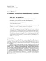
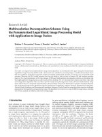
3.1. The Embedding Procedure. The proposed watermark
embedding scheme is shown in Figure 1.Ourproposed
method is based on the idea of paper [14] proposed by
Zhu and Sang. Their method modifies the DC compo-
nents of discrete cosine transform (DCT) domain using
quantification to embed watermark; however the quantifi-
cation approach is rather complicated and less effective,
and all DC coefficientvaluesareutilized.Inourcase,
we propose to use wave-atom coefficients with a much
more simplified quantization approach with only two levels
for each bit embedded, and only selective coefficients are
used for modification purpose giving better susceptibil-
ity against attacks. The embedding process is described
as follows.
(1) Divide the original image I of size M
×N to form four
subimages, I
1
, I
2
, I
3
,andI
4
, using (6).
(2) Wave-atom Transform is then applied to the four
subimages. Accordingly, these subimages are decom-
posed into five bands in our case. The fourth-scale
band is selected to embed watermark w.
(3) Select the coefficients C
u
from the sets S
1
, S
2
, S
3
,and
S
4
whose absolute values are smaller than r to modify
and label as D
u
,whereu = (j, m
1
, m
2
, n
1
, n
2
)of
integer-valued quantities index is a point (x
u
, ω
u
)in
phase space.
(4) Suppose that Z
u
= D
u
mod Q. The function mod
computes modulus after division. Q is a quantifica-
tion threshold for adjusting watermark embedding
EURASIP Journal on Advances in Signal Processing 3
Decompose into 4
Divide into 5 bands
Discrete waveatom
transform
Inverse discrete
waveatom
transform
Select suitable
coefficients
Compare and modify the
coefficients according to Z
u
Collecting 4 sub-
images and form
watermarked image
Watermark
Watermarked image
Original image
subimages
Figure 1: The embedding procedure.
depth and can affect the watermarked image quality
and the robustness of the embedded watermark.
If Q is too small, embedding watermark robustness
will be worse; if Q is too large, it will degrade the
quality of the watermarked image, and, therefore, Q
is chosen properly based on the detailed application
condition of watermark. In our proposed method,
one wave atom wedge is used for embedding one bit.
Thus, more than one coefficient will get modified in
the wedge and they represent the same bit. Assume
that the length of watermark bits is l.
When embedding bit w
c
= 0,
D
u
=
⎧
⎪
⎪
⎪
⎨
⎪
⎪
⎪
⎩
D
u
+
Q
4
− Z
u
if Z
u
∈
0,
3Q
4
,
D
u
+
5Q
4
− Z
u
if Z
u
∈
3Q
4
, Q
.
(7)
When embedding bit w
c
= 1,
D
u
=
⎧
⎪
⎪
⎪
⎨
⎪
⎪
⎪
⎩
D
u
−
Q
4
− Z
u
if Z
u
∈
0,
Q
4
,
D
u
+
3Q
4
− Z
u
if Z
u
∈
Q
4
, Q
,
(8)
where c
= 1, 2, , l.
(5) Repeat the above process until embedding all bits
and apply the inverse wave-atom transform to the
modified coefficients sets.
(6) Obtain the output watermarked image I
by collect-
ing 4 modified subimages.
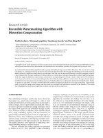
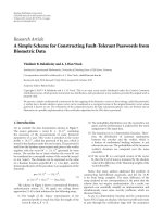
3.2. The Ext racting Procedure. Suppose that I
is the water-
marked image for watermark detection. When extracting
the watermark sequence, our watermarking model does not
need the original image. The proposed watermark extraction
scheme is shown in Figure 2. The extracting process is
described as follows.
(1) Divide I
to four subimages, I
1
, I
2
, I
3
,andI
4
, using
(6).
(2) Wave-atom transform is then applied to subima-
ges I
1
, I
2
, I
3
,andI
4
to obtain four coefficients sets, S
1
,
S
2
, S
3
,andS
4
.
(3) Similar to the embedding phase, watermar k is
extracted from the fourth scale band. First, select
coefficient C
u
within the sets S
1
, S
2
, S
3
,andS
4
whose
absolute values are smaller than r to modify and label
as D
u
,whereu = ( j, m
1
, m
2
, n
1
, n
2
)ofinteger-valued
quantities index is a point (x
u
, ω
u
) in phase space.
(4) Calculate Z
u
= D
u
mod Q.Leth denote the number
of coefficient D
u
inside a wave atom wedge δ
j,m1,m2
.
The watermark sequence t
c
is extracted as follows.
For a nonempty wedge δ
j,m1,m2
,
t
c
(
k
)
=
⎧
⎪
⎪
⎪
⎨
⎪
⎪
⎪
⎩
0ifZ
u
∈
0,
Q
2
,
1ifZ
u
∈
Q
2
, Q
,
(9)
where k
= 1, 2, , h and c = 1, 2, , l.
Asequencet
c
is obtained, which is used for extracting
correct watermark bits.
(5) Finally, the watermark w
c
can be reconstructed as
follows:
w
c
=
⎧
⎨
⎩
0 ifnumberofbit0int
c
> number of bit 1 in t
c
,
1 ifnumberofbit1int
c
≥ number of bit 0 in t
c
,
(10)
where c
= 1, 2, , l.
4 EURASIP Journal on Advances in Signal Processing
Decompose into 4
Divide into 5 bands
Discrete waveatom
transform
At the fourth scale
band, compute and
compare the modulus Z
u
Compare number of bit 1
and form the final
watermark
Watermarked image
Extracted watermark
subimages
and bit 0 in sequence t
i
Figure 2: The extracting procedure.
Table 1: The values of PSNR.
PSNR value of watermarked lena image (dB)
Zhu and Sang [14] 54.329
Xiao et al. [16] 44.5323
Leung et al. [17] 42.8072
Tao and Eskicioglu [18] 35.8
Ni et al. [19] 44.7
Proposed scheme 40.379
The proposed method is similar to the quantization
index modulation- (QIM-) based watermarking schemes.
QIM was first proposed by Chen and Wornell [15]. In
Chen’s method, there are two uniform quantizers Q
0
(s)
and Q
1
(s) for watermark embedding, while we simplify the
approach and use only one quantizer Q which enhances
the computation efficiency. Our step size of the proposed
method is Q/2. To embed the watermark, we shift the
modulusvaluesofwaveatomcoefficients to the median
of the interval or to the nearest median of the neighbor
intervals according to the watermark bit. If the values are
within the desired interval, they need to be moved to
the median of the same interval. However, if the values
are placed in the undesired interval, they need to be
shifted to the median of the nearest neighbor interval.
Thus, the proposed simplified quantization index modu-
lation approach can speed up the entire extraction pro-
cess.
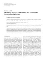
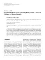
4. Experimental Results
The experimental results of the proposed watermarking
scheme are presented in this section. In order to test the
robustness of the proposed watermarking scheme, we used
the 512
× 512 gray-scale image, Lena, shown in Figure 3(a)
as the test image. The watermarked image is illustrated
in Figure 3(b), which has good visual quality. The binary
watermark is shown in Figure 3(c), whose size is 16
× 16.
The extracted watermark is shown in Figure 3(d) with
NC value
= 1 which shows the correct watermark extraction.
Our experimental system is composed of an Intel Core-Quad
CPU with a 2.66 GHz core and 3 GB DDR2.
In the experiments, the quantification threshold Q is 24
and the threshold of coefficient selection r is 60. The mean
squared error (MSE) between the original and watermarked
images is defined by
MSE
=
1
M · N
M
i=1
N
j=1
I
i, j
−
I
i, j
2
, (11)
where I(i, j)andI
(i, j) denote the pixel value at position
(i, j) of the original image I and the watermarked image I
with size of M × N pixels, respectively.
Hence, the watermarked image quality is represented by
the peak signal-to-noise ratio (PSNR) between I and I
and
is calculated by
PSNR
= 10 log
10
255
2
MSE
(
dB
)
. (12)
To evaluate the robustness of the algorithm, the nor-
malized cross-correlation (NC) is employed. More similar
watermarks will get a larger NC value. The NC between the
embedded watermark, W(i, j), and the extracted watermark
W
(i, j)isdefinedby
NC
=
M
W
i=1
N
W
j=1
W
i, j
·
W
i, j
M
W
i=1
N
W
j=1
W
i, j
2
, (13)
where M
W
and N
W
denote the width and height of the
watermark, respectively.
4.1. Robustness Tests. Several common signal processing
attacks are applied to verify the robustness of the proposed
scheme including Gaussian low-pass filtering, Gaussian
additive noise, Laplacian image enhancement, JPEG com-
pression, and salt and pepper noises. Furthermore, we
compare the performance of the proposed scheme with other
EURASIP Journal on Advances in Signal Processing 5
Table 2: Experiment results comparison under Gaussian noises (NC values).
Standard variance of Gaussian noises 6 8 10 12 14 16 18 20 25 30
Zhu and Sang [14] 0.9254 0.8718 0.7912 0.7033 0.639 0.5844 0.5927 0.582 0.4947 0.4869
Xiao et al. [16] 0.9926 0.9778 0.9738 0.9778 0.955 0.963 0.9511 0.9403 0.9129 0.893
Leung et al. [17] 1 0.9926 0.9889 0.9853 0.9891 0.9553 0.9312 0.9315 0.8508 0.8596
Tao and Eskicioglu [18] 0.8584 0.822 0.7974 0.7772 0.7634 0.7538 0.7476 0.7405 0.731 0.7231
Proposed scheme 1 0.9816 0.9591 0.8226 0.6674 0.5333 0.5414 0.4926 0.4963 0.5319
Table 3: Experiment results comparison under salt and pepper noises (NC values).
Density parameter of “salt and pepper noises” 0.02 0.04 0.06 0.08 0.1 0.12 0.14 0.16 0.18 0.2
Zhu and Sang [14] 0.5986 0.4983 0.4776 0.5346 0.5291 0.5441 0.5235 0.4772 0.4433 0.4851
Xiao et al. [16] 0.9587 0.9024 0.8263 0.8196 0.7981 0.7856 0.7729 0.7407 0.7766 0.696
Leung et al. [17] 0.9093 0.8677 0.7916 0.7658 0.7648 0.6594 0.6971 0.6807 0.7213 0.6393
Tao and Eskicioglu [18] 0.9784 0.9579 0.9386 0.9209 0.9035 0.8869 0.8714 0.8559 0.8437 0.8301
Proposed scheme 0.5804 0.4605 0.5481 0.5284 0.5037 0.5299 0.5271 0.5821 0.5401 0.5004
Table 4: Experiment results comparison under Laplacian sharpening (NC values).
Laplacian parameter 0.1 0.2 0.3 0.4 0.5 0.6 0.7 0.8 0.9 1
Zhu and Sang [14] 0.7565 0.7565 0.7638 0.7721 0.7693 0.7783 0.7783 0.7884 0.7783 0.7794
Xiao et al. [16] 0.9963 0.9963 0.9963 0.9963 0.9963 0.9963 0.9963 0.9963 0.9963 0.9963
Leung et al. [17] 0.9963 0.9963 0.9963 0.9963 0.9963 0.9963 0.9963 0.9963 0.9963 0.9963
Tao and Eskicioglu [18] 0.7967 0.7975 0.8007 0.8028 0.8044 0.8083 0.8082 0.8095 0.8109 0.8215
Proposed scheme 0.6268 0.6256 0.6421 0.674 0.6643 0.6692 0.7015 0.6963 0.728 0.7253
Table 5: Experiment results comparison under Jpeg compression (NC values).
Jpegcompressionparameter806040353025201510 5
Zhu and Sang [14] 1 1 0.9785 0.9813 0.7303 0.914 0.6407 0.7026 0.3899 0.7057
Xiao et al. [16] 0.9553 0.9093 0.9481 0.8657 0.8074 0.8955 0.7427 0.7454 0.6915 0.6519
Leung et al. [17] 1 1 0.9963 0.9963 1 0.9853 0.9704 0.9289 0.7761 0.6138
Tao and Eskicioglu [18] 0.9704 0.9245 0.891 0.881 0.8682 0.8558 0.8382 0.818 0.7858 0.7413
Ni et al. [19] 0.9547 0.7550 0.5314 N/A N/A N/A N/A N/A N/A N/A
Proposed scheme 0.9963 0.9813 0.9524 0.9403 0.9231 0.8889 0.8493 0.7427 0.6256 0.5735
Table 6: Experiment results comparison under low-pass filtering (NC values).
Standard variance (w indow) of “low-pass filtering” 0.5 (3) 1.5 (3) 0.5 (5) 1.5 (5) 3 (5)
Zhu and Sang [14] 0.9214 0.8206 0.9214 0.9179 0.8422
Xiao et al. [16] 0.9889 0.9706 0.9889 0.9299 0.8541
Leung et al. [17] 11111
Tao and Eskicioglu [18] 0.9697 0.912 0.9695 0.8741 0.8582
Proposed scheme 1 0.9926 0.9963 0.853 0.6114
Table 7: Experiment results comparison under cropping (NC values).
Cropping Ty pe 1 (Figure 4(f)) Type 2 (Figure 4(g)) Type 3 (Figure 4(h)) Ty pe 4 (Figure 4(i)) Type 5 (Figure 4(j))
Zhu and Sang [14] 0.7262 1 0.7262 1 1
Xiao et al. [16] 0.8001 0.8756 0.8046 0.8095 0.853
Leung et al. [17] 0.9118 0.9158 0.8888 0.869 0.8748
Tao and Eskicioglu [18] 0.678 0.8611 0.6788 0.6758 0.6768
Proposed scheme 0.9889 0.9702 0.8074 0.8474 0.9058
6 EURASIP Journal on Advances in Signal Processing
(a) Lena image (b) Watermarked Lena image
(c) Binary watermark (d) ExtractedwatermarkwithNC= 1
Figure 3
Table 8: Experiment results comparison under luminance attacks
(NC values).
Luminance
20%
Brighter
40%
Brighter
20%
Darker
40%
Darker
Zhu and Sang
[14]
0.5224 0.6928 0.7484 0.5264
Xiao et al. [16] 0.9926 0.9926 0.9926 0.9926
Leung et al. [17]1 1 1 1
Tao an d
Eskicioglu [18]
0.9505 0.9505 0.0273 N/A
Ni et al. [19] 1 0.9329 1 1
Proposed
scheme
1 0.9926 0.9963 0.9814
Table 9: Experiment results comparison under contrast attacks
(NC values).
Contrast
20%
Increase
40%
Increase
20%
Decrease
30%
Decrease
Zhu and Sang
[14]
0.618 0.5143 0.7783 0.4869
Xiao et al. [16] 0.9926 0.9926 0.9926 0.9926
Leung et al. [17]1111
Tao an d
Eskicioglu [18]
0.6041 0.5742 0.8297 0.6995
Ni et al. [19] 1 1 0.976 0.6809
Proposed scheme 1 0.9662 0.9963 0.9888
watermarking schemes which are proposed by Zhu and Sang
[14], Xiao et al. [16], Leung et al. [17], Tao and Eskicioglu
[18],andNietal.[19]. Tables 1–10 show the performance of
these watermarking schemes in term of the normalized cross-
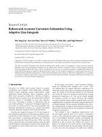
correlation values and PSNR values. The attacked images are
presented in Figure 4 with the parameters used for different
attacks.
Table 10: Experiment results comparison under median filtering
and histogram equalization (NC values).
Attacks Median filtering (3 × 3)
Histogram
equalization
Zhu and Sang [14] 0.9889
0.5058
Xiao et al. [16] 0.9742
0.9927
Leung et al. [17]1
1
Tao and Eskicioglu [18] 0.9232
0.8877
Proposed scheme 0.9926
0.9926
From Table 1, we can see that the PSNR value of water-
marked image using our proposed method is 40.379 dB,
which is comparable to other watermarking schemes. This
indicates that the proposed watermarking scheme has good
visual fidelity. Zhu’s scheme obtains the best watermarked
image quality, while Tao’s scheme is the worst one.
For the Gaussian noises attacks, the proposed scheme
outperforms Tao’s and Zhu’s schemes but is little worse
than other schemes as shown in Table 2. From Tables 3
and 4, it can be seen that the proposed method is not
robust against the salt and pepper noises and Laplacian
sharpening. Compared with Zhu’s, Xiao’s, Leung’s, and Tao’s
schemes, it is observed that there is hig her robustness to
JPEG compression with the proposed scheme. Related results
are shown in Table 5. Besides, for low-pass filtering, it
is observed that the robustness of proposed method is
relatively better than Zhu’s, Tao’s, and Xiao’s algorithms
when the window size and variance are small, where the NC
values are closed to 1 as shown in Table 6. For cropping
attacks, our proposed method generally outperforms other
watermarking schemes in al l cases except the Zhu one which
is summarized in Table 7. Tables 8 and 9 highlight the
results achieved for luminance and contrast attacks. From
the results, the proposed method outperforms other four
algorithms except the Leung one, where the NC values are
about 0.8 to 1. Table 10 shows that the proposed method
EURASIP Journal on Advances in Signal Processing 7
(a) Guassian noises (Standard variance =
30)
(b) Salt and pepper noises
(Density parameter
= 0.1)
(c) Laplacian sharpening (parameter =
0.1)
(d) Jpeg compression (QF = 5) (e) Low-pass filtering (Standard variance
(window) equal 0.5(5))
(f) Cropping (Type 1)
(g) Cropping (Type 2) (h) Cropping (Type 3) (i) Cropping (Type 4)
(j) Cropping (Type 5) (k) 40% Brighter (l) 40% Darker
Figure 4: Continued.
8 EURASIP Journal on Advances in Signal Processing
(m) 40% Contrast increase (n) 30% Contrast decrease (o) Median filtering
(p) Histogram equalization
Figure 4: Attacks on the watermarked image Lena.
is more robust than Zhu’s, Xiao’s, and Tao’s algorithms for
median filtering and histogram equalization.
Besides, we also per formed some numerical experiments
with other gray-scale standard images such as “Boat”, “Pep-
per”, and “Airplane”. The PSNR values for all watermarked
images are over 40 dB. Most simulation results are the same
as using the image “Lena” except histogram equalization. The
watermark of the proposed method only survives histogram
equalization in images “Lena” and “Pepper”. For the images
“Boat” and “Airplane”, the NC values are only 0.6886 and
0.4503, respectively.
Tab le 11 summarizes the processing time for watermar k
embedding and retrieval. Image Lena is used. It shows that
the processing time of our proposed scheme is longer than
that of Zhu’s scheme but shorter than those of other four
schemes, which are 2.03 s a nd 2.07 s for embedding and
extracting, respectively. The processing time of proposed
scheme is acceptable compared with other watermarking
schemes. Overall, our proposed method achieved relatively
better performance than those of Zhu and Sang [14], Tao
and Eskicioglu [18], and Ni et al. [19] and obtained great
robustness.
5. Conclusion
In this paper, a robust watermarking scheme based on
the wave-atom transform is presented. The watermark is
Table 11: The processing time for watermark embedding and
retrieval.
Processing time for
watermark
embedding (s)
Processing time for
watermark retrieval
(s)
Zhu and Sang [14] 1.02 0.38
Xiao et al. [16] 6.22 2.31
Leung et al. [17] 6.41 5.37
Tao and Eskicioglu [18] 0.9 9.45
Proposed scheme 2.23 2.07
embedded in the wave-atom domain of four subimages. The
watermark extraction process is simple and does not need
the original image. The main idea of our proposed method
is based on adjusting the coefficient modulus after division.
The quality of the watermarked image is good in terms of
perceptibility and PSNR (over 40 dB). By comparing with
other watermarking schemes, the experimental results show
that our proposed method is more robust against attacks
such as JPEG compression, median filtering, Gaussian
filtering, cropping, luminance, and contrast attacks, but it
fails against salt and pepper noises and sharpening attacks.
The results show that the proposed method outperforms
the DCT [14], wavelet [18], iterative mapping [19], and
blind curvelet [16] and as expected works slightly worse
EURASIP Journal on Advances in Signal Processing 9
than the curvelet nonblind approaches [17]. To conclude,
from the experimental results, it is believed that digital
watermarking using wave atom is able to obtain great
robustness.
References
[1] C. I. Podilchuk and E. J. Delp, “Digital watermarking:
algorithm and application,” IEEE Signal Processing Magazine,
vol. 18, no. 4, pp. 33–46, 2001.
[2] I. J. Cox, J. Kilian, F. T. Leighton, and T. Shamoon, “Secure
spread spectrum watermarking for multimedia,” IEEE Trans-
actions on Image Processing, vol. 6, no. 12, pp. 1673–1687, 1997.
[3] S. Katzenbeisser and F. A. P. Petitcolas, Information Hid-
ing Techniques for Steganography and Digital Watermarking,
Artech House, Boston, Mass, USA, 2000.
[4] C S. Shieh, H C. Huang, F H. Wang, and J S. Pan, “Genetic
watermarking based on transform-domain techniques,” Pat-
tern Recognition, vol. 37, no. 3, pp. 555–565, 2004.
[5] F. Y. Shih and S. Y. T. Wu, “Combinational image watermark-
ing in the spatial and frequency domains,” Pattern Recognition,
vol. 36, no. 4, pp. 969–975, 2002.
[6] P. Tao and A. M. Eskicioglu, “A robust multiple watermarking
scheme in the discrete wavelet transform domain,” in Internet
Multimedia Management Systems V, Proceedings of SPIE, pp.
133–144, Philadelphia, Pa, USA, October 2004.
[7] L. Demanet, Curvelets, wave atoms, and wave equations,Ph.D.
thesis, Caltech, 2006, />∼laurent/
papers/ThesisDemanet.pdf.
[8] L. Demanet and L. Ying, “Wave atoms and sparsity of
oscillatory patterns,” Applied and Computational Harmonic
Analysis, vol. 23, no. 3, pp. 368–387, 2007.
[9] J. Rajeesh, R. S. Moni, and S. Palanikumar, “Noise reduction in
magnetic resonance images using wave atom shrinkage,” The
International Journal of Image Processing, vol. 4, no. 2, pp. 131–
141, 2010.
[10] A. Federico and G. H. Kaufmann, “Denoising in digital speckle
pattern interferometry using wave atoms,” Optics Letters, vol.
32, no. 10, pp. 1232–1234, 2007.
[11] A. S. Lewis and G. Knowles, “Image compression using the 2-
Dwavelettransform,”IEEE Transactions of Image Processing,
vol. 1, no. 2, pp. 244–250, 1992.
[12] L. Demanet and L. Ying, “Wave atoms and time upscaling of
wave equations,” Numerische Mathematik, vol. 113, no. 1, pp.
1–71, 2009.
[13] />[14] G. Zhu and N. Sang, “Watermarking algorithm research and
implementation based on DCT block,” World Academy of
Science, Engineering and Technology, vol. 45, pp. 38–42, 2008.
[15] B. Chen and G. W. Wornell, “Quantization index modulation:
a class of provably good methods for digital watermarking and
information embedding,” IEEE Transactions on Information
Theory, vol. 47, no. 4, pp. 1423–1443, 2001.
[16] Y. Xiao, L. M. Cheng, and L. L. Cheng, “A robust image
watermarking scheme based on a novel HVS model in curvelet
domain,” in Proceedings of the 4th International Conference
on Intelligent Information Hiding and Multimedia Signal
Processing (IIH-MSP ’08), pp. 343–347, Harbin, China, August
2008.
[17] H. Y. Leung, L. M. Cheng, and L. L. Cheng, “A robust
watermarking scheme using selective curvelet coefficients,”
International Journal of Wavelets, Multiresolution and Informa-
tion Processing, vol. 7, no. 2, pp. 163–181, 2009.
[18] P. Tao and A. M. Eskicioglu, “A robust multiple watermarking
scheme in the Discrete Wavelet Transform domain,” in Internet
Multimedia Management Systems V, vol. 5601 of Proceedings of
SPIE, pp. 133–144, Philadelphia, Pa, USA, October 2004.
[19] R. Ni, Q. Ruan, and H. D. Cheng, “Secure semi-blind water-
marking based on iteration mapping and image features,”
Pattern Recognition, vol. 38, no. 3, pp. 357–368, 2005.