Báo cáo hóa học: " Research Article Complexity-Reduced MLD Based on QR Decomposition in OFDM MIMO Multiplexing with " pptx
Bạn đang xem bản rút gọn của tài liệu. Xem và tải ngay bản đầy đủ của tài liệu tại đây (1.9 MB, 15 trang )
Hindawi Publishing Corporation
EURASIP Journal on Advances in Signal Processing
Volume 2011, Article ID 525829, 15 pages
doi:10.1155/2011/525829
Research Article
Complexity-Reduced MLD Based on QR Decomposition in
OFDM MIMO Multiplexing with Frequency Domain Sprea ding
and Code Multiplexing
Kouji Nagatomi,
1
Hiroyuki Ka wai,
2
and Kenichi Higuchi
1
1
Department of Electrical Engineering, Tokyo University of Science, 2641 Yamazaki, Noda, Chiba 278-8510, Japan
2
Radio Access Network Development Department, NTT DOCOMO, INC., 3-5 Hikari-no-oka, Yokosuka, Kanagawa 239-8536, Japan
Correspondence should be addressed to Kenichi Higuchi,
Received 12 April 2010; Revised 30 June 2010; Accepted 19 August 2010
Academic Editor: Naofal Al-Dhahir
Copyright © 2011 Kouji Nagatomi et al. This is an open access article distributed under the Creative Commons Attribution
License, which permits unrestricted use, distribution, and reproduction in any medium, provided the original work is properly
cited.
This paper presents a new maximum likelihood detection- (MLD-) based signal detection method for or thogonal frequency
division multiplexing (OFDM) multiple-input multiple-output (MIMO) multiplexing with frequency domain spreading and
code multiplexing. The proposed MLD reduces the computational complexity by utilizing signal orthogonalization based on QR
decomposition of the product of the channel and spreading code matrices in the frequency domain. Simulation results show that
when the spreading factor and number of code multiplexed symbols are 16, the proposed MLD reduces the average received signal
energy per bit-to-noise spectrum density ratio (E
b
/N
0
)fortheaveragepacketerrorrate(PER)of10
−2
by approximately 12 dB
compared to the conventional minimum mean-squared error- (MMSE-) based filtering for 4-by-4 MIMO multiplexing (16QAM
with the rate-3/4 Turbo code is assumed).
1. Introduction
Orthogonal frequency division multiplexing (OFDM) is
a promising modulation/radio access scheme for future
wireless communication systems because of its inherent
immunity to multipath interference due to a low symbol
rate and the use of a cyclic prefix (CP), and its affinity to
different transmission bandwidth arrangements. OFDM has
already been adopted as a radio access scheme for several
of the latest cellular system specifications such as the long-
term evolution (LTE) system in the 3GPP (3rd Generation
Partnership Project) [1].
One of the major drawbacks of the OFDM signal based
on multicarrier transmission is the high peak-to-average
power ratio (PAPR) of the transmit signal. The OFDM
signal also cannot achieve symbol-level multipath diversity
(frequency diversity in the frequency domain) since each of
the narrow-band subcarriers experiences flat fading variation
even in multipath fading environments, although some
frequency diversity gain is obtained by using channel coding.
One approach to achieve a lower PAPR and multipath
diversity gain in the OFDM signal is to use frequency domain
spreading and code multiplexing (in other words, linear
precoding before the inverse fast Fourier transform (IFFT)
modulation at the transmitter) [2–9]. Code multiplexing is
needed if we want to maintain the same frequency efficiency
as that without frequency domain spreading. In general, by
using the frequency domain spreading at the transmitter and
frequency domain despreading at the receiver, symbol-level
frequency domain diversity is achieved in a multipath fading
channel [2–5]. Furthermore, by selecting an appropriate set
of spreading codes, frequency domain spreading and code
multiplexing in the OFDM signal can reduce the PAPR
[6–9]. In particular, when the discrete Fourier transform
(DFT) sequence is used as a spreading code, which is called
DFT-Spread OFDM [1, 8, 9], a very low PAPR, which
is the same as that of the single carrier transmission, is
achieved.
In general, the use of frequency domain spreading and
code multiplexing, however, loses the inherent immunity
2 EURASIP Journal on Advances in Signal Processing
of the OFDM signal to multipath interference. Thus, inter-
symbol interference (ISI) occurs in a multipath fading chan-
nel. The ISI between code-multiplexed symbols degrades the
transmission quality of the OFDM signal with frequency
domain spreading and code multiplexing especially when
space div ision multiplexing (SDM; hereafter referred to as
multiple-input multiple-output (MIMO) multiplexing) [10]
is applied to achieve a high data rate.
The use of frequency domain spreading and code mul-
tiplexing also restricts the use of powerful sig nal detection
methods. Maximum likelihood detection (MLD) is know n
as an optimum signal detection scheme for MIMO multi-
plexing [11]. However, when frequency domain spreading
and code multiplexing is applied to the OFDM signal, the
number of symbol candidates is exponentially increased to
2
N
R
N
TX
N
SF
, where N
R
is the number of bits conveyed by one
symbol, N
TX
is the number of the transmitter antennas,
and N
SF
is the spreading factor that equals the number of
code multiplexed symbols. Therefore, the use of MLD is
not realistic and a low-complexity signal detector such as
linear filtering based on the minimum mean-squared error
(MMSE) must be used. This is another reason why the bit
error rate (BER) and packet error rate (PER) of MIMO
multiplexing with the OFDM signal using frequency domain
spreading and code multiplexing are deteriorated compared
to that of OFDM MIMO multiplexing without spreading.
This paper presents a new MLD-based signal detection
method for OFDM MIMO multiplexing with frequency
domain spreading and code multiplexing. The proposed
MLD-based signal detection method is based on the QR
decomposition- (QRD-) M algorithm [12] (or QRM-MLD
in [13]) for OFDM MIMO multiplexing, which applies
signal orthogonalization based on QR decomposition of
the spatial channel matrix and quasi-MLD using the com-
putationally efficient M-algorithm on the orthogonalized
signal for each subcarrier independently. However, when we
assume frequency domain spreading and code multiplexing,
the signal constellation per transmitter antenna still has
2
N
R
N
SF
points although the spatially multiplexed symbols are
decomposed if we employ the per subcarrier-based QRD-M
or QRM-MLD. Therefore, in order to decompose fully
the spatial and code multiplexed tr ansmit sy mbols at the
receiver, the proposed MLD receiver jointly considers all the
subcarriers to which the spread symbols are mapped and
constructs the overall frequency-domain linear transforma-
tion matrix, which is a product of the space and frequency-
domain channel matrix and spreading code matrix. The
QR decomposition of the overall frequency-domain linear
transformation matrix is performed to derive the orthog-
onalized received signal vector. Then, the M-algorithm is
used to achieve computationally efficient quasi-MLD with
the orthogonalized received signal vector. We note that the
MMSE-based Turbo equalization, for example, in [14–17], is
another powerful candidate for signal detection for OFDM
MIMO multiplexing with frequency domain spreading and
code multiplexing. A possible advantageous property of the
proposed MLD against the MMSE-based Turbo equalization
can be a shorter processing delay as the proposed MLD does
not require iterative signal detection and Turbo decoding
which is different from Turbo equalization. The computa-
tional complexity of the proposed MLD may be higher than
that of the MMSE-based Turbo equalization as N
SF
increases.
A detailed comparison of the proposed MLD and the MMSE-
based Turbo equalization is outside the scope of the paper
and is left for future study.
In the paper, we also propose a spreading code-first
ordering method of spatial/code-multiplexed symbols that
are to be detected in order to decrease the symbol selection
error in the proposed MLD due to the fading correlation
between the code-multiplexed symbols transmitted from the
same transmitter antenna. The reminder of the paper is
organized as follows. First, Section 2 describes the proposed
MLD-based signal detection method. Then in Section 3,
we present a set of simulation results to show the PER
improvement when using the proposed MLD compared to
the MMSE-based linear filtering . Finally, Section 4 concludes
the paper.
2. Complexity-Reduced MLD for OFDM MIMO
Multiplexing with Frequency Domain
Spreading and Code Multiplexing
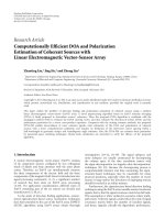
2.1. Basic Structure of Proposed MLD. Figure 1 shows a
block diagram of the OFDM MIMO transmitter using
frequency domain spreading and code multiplexing. In the
following, we assume that the number of subcarriers of
interest is equal to the spreading factor, N
SF
, for the sake
of simplicity. Furthermore, we assume that the number of
code multiplexing is equal to N
SF
in order to maintain the
same frequency efficiency as that without frequency domain
spreading.
The N
SF
× 1-dimensional transmit data symbol vector,
s
n
, which will be spread and code-multiplexed later, from the
nth (1
≤ n ≤ N
TX
) transmit antenna is represented as
s
n
=
s
n,1
s
n,2
··· s
n,N
SF
t
,(1)
where s
n,b
is the bth (1 ≤ b ≤ N
SF
) data symbol from the
nth transmit antenna and (
·)
t
is the transpose operation.
The N
SF
× 1-dimensional spreading code sequence vector,
w
i
, each of whose elements is multiplied to each data symbol
at the ith (1
≤ i ≤ N
SF
) subcarrier, is expressed as
w
i
=
w
i,1
w
i,2
··· w
i,N
SF
t
,(2)
where w
i,b
is the spreading code multiplied to the bth data
symbol at the ith subcarrier. Spreading code sequence vector
w
i
is the ith column vector of the N
SF
× N
SF
-dimensional
spreading code matrix, W. In general, a unitary matrix is
used as W. Since we assume DFT-Spread O FDM in the
following evaluation, each of the column vectors of the
EURASIP Journal on Advances in Signal Processing 3
S/P
Copy
IFFT
+
+
+
CP
add
Frequency domain spreading
and code-multiplexing
To a nten na
1
n
Coded
data
symbols
S/P
N
SF
N
SF
N
SF
.
.
.
.
.
.
w
1,b
w
i,b
w
N
SF
,b
s
n,b
w
t
i
s
n
N
T
X
Figure 1: Block diagram of the OFDM MIMO transmitter using frequency domain spreading and code multiplexing.
CP
del.
FFT
CP
del.
FFT
Received
signal
1
N
SF
N
RX
Channel
estimation
QRD of
matrix F
Spreading code
information
Q
H
mul.
H
all
W
all
M-
algorithm
Q
R
LLR
calc.
To
channel
decoder
.
.
.
.
.
.
N
TX
N
SF
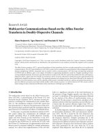
Figure 2: Block diagram of the proposed MLD-based signal detection.
N
SF
× N
SF
-dimensional DFT matrix, W
DFT
, is used as w
i
in
the paper:
W
DFT
=
w
1
w
2
··· w
N
SF
=
⎡
⎢
⎢
⎢
⎢
⎣
w
1
w
2
.
.
.
w
N
SF
⎤
⎥
⎥
⎥
⎥
⎦
=
1
N
SF
φ
N
SF
(l−1)(i−1)
,
(3)
where φ
N
SF
= e
− j2π/N
SF
,andl and i represent the index for
the rows and columns of W
DFT
,respectively(1≤ l, i ≤ N
SF
).
The 1
× N
SF
-dimensional spreading code sequence vector,
w
b
, can be seen as a spreading code sequence for the bth data
symbol. It should be noted that the same matrix, W
DFT
,is
commonly used for spreading at all the transmitter antennas.
The transmit signal from the nth transmit antenna at the
ith subcarrier is represented as w
t
i
s
n
. The frequency-domain
transmit signal is converted to a time-domain transmit signal
by inverse fast Fourier transform (IFFT) operation and
transmitted after appending a CP.
We define N
RX
× N
TX
-dimensional matrix H
i
assuming
that N
RX
is the number of receiver antennas, which comprises
channel coefficients for all the combinations of transmitter
and receiver antennas for the ith subcarrier:
H
i
=
⎡
⎢
⎢
⎢
⎢
⎣
h
i,1,1
h
i,1,2
··· h
i,1,N
TX
h
i,2,1
h
i,2,2
.
.
.
.
.
.
h
i,N
RX
,1
h
i,N
RX
,N
TX
⎤
⎥
⎥
⎥
⎥
⎦
. (4)
Here h
i,m,n
denotes the channel coefficient between the nth
transmit antenna and the mth (1
≤ m ≤ N
RX
)receiver
antenna at the ith subcarrier.
At the receiver, after the CP removal, the time-domain
received signal is converted to a frequency-domain signal by
FFT operation at each receiver antenna branch. Assuming
that the time difference in the propagation delay of all
the multipaths is within the CP duration, the N
RX
× 1-
dimensional frequency-domain received signal vector, r
i
,for
the ith subcarrier is represented as
r
i
= H
i
⎡
⎢
⎢
⎢
⎢
⎢
⎣
w
t
i
s
1
w
t
i
s
2
.
.
.
w
t
i
s
N
TX
⎤
⎥
⎥
⎥
⎥
⎥
⎦
+ n
i
= H
i
diag
w
t
i
s
t
1
s
t
2
··· s
t
N
TX
t
+ n
i
= H
i
W
i
s
all
+ n
i
,
(5)
4 EURASIP Journal on Advances in Signal Processing
W
i
= diag
w
t
i
,(6)
s
all
=
s
t
1
s
t
2
··· s
t
N
TX
t
,(7)
where diag
{w
t
i
} is the N
TX
× N
TX
N
SF
-dimensional block
diagonal matrix all of whose block diagonal components are
w
t
i
and hereafter is simply denoted as W
i
.TheN
TX
N
SF
× 1-
dimensional vector, s
all
, is the overall transmit data symbol
vector whose ((n
− 1)N
SF
+ b)th element represents the bth
data symbol transmitted from the nth transmit antenna.
Vec tor n
i
is an N
RX
× 1-dimensional receiver noise vector
assuming i.i.d. additive white Gaussian noise (AWGN).
The overall frequency-domain received signal vector is
represented as
r
all
=
⎡
⎢
⎢
⎢
⎢
⎣
r
1
r
2
.
.
.
r
N
SF
⎤
⎥
⎥
⎥
⎥
⎦
=
⎡
⎢
⎢
⎢
⎢
⎣
H
1
W
1
H
2
W
2
.
.
.
H
N
SF
W
N
SF
⎤
⎥
⎥
⎥
⎥
⎦
s
all
+
⎡
⎢
⎢
⎢
⎢
⎣
n
1
n
2
.
.
.
n
N
SF
⎤
⎥
⎥
⎥
⎥
⎦
=
H
all
W
all
s
all
+ n
all
= Fs
all
+ n
all
,
(8)
H
all
= diag
H
1
H
2
··· H
N
SF
,(9)
W
all
=
W
t
1
W
t
2
··· W
t
N
SF
t
, (10)
n
all
=
n
t
1
n
t
2
··· n
t
N
SF
t
, (11)
F
= H
all
W
all
, (12)
where F denotes the matrix of size N
RX
N
SF
× N
TX
N
SF
,which
comprises the product of the extended channel matrix and
spreading code matrix in the frequency domain.
In the proposed MLD-based sig nal detection, F is
estimated at the receiver from the channel estimate and
known spreading code matrix. Next, QR decomposition is
performed on the estimated
F:
F =⇒ QR. (13)
Matrix Q is an N
RX
N
SF
× N
TX
N
SF
-dimensional unitary
matrix and R is an N
TX
N
SF
× N
TX
N
SF
-dimensional upper
triangular matrix. Assuming that
F has no estimation error,
the orthogonalization of the received signal vector is achieved
by multiplying the Hermitian transpose of matrix Q to the
overall frequency-domain received signal vector:
z
= Q
H
r
all
= Q
H
(
Fs
all
+ n
all
)
= Q
H
(
QRs
all
+ n
all
)
= Rs
all
+ Q
H
n
all
.
(14)
Here (
·)
H
denotes the Hermitian transpose operation. Vector
z is the N
TX
N
SF
× 1-dimensional orthogonalized received
signal vector. Since matrix Q is unitar y, the transformed
N
TX
N
SF
× 1-dimensional receiver noise vector Q
H
n
all
still
maintains the i.i.d. AWGN property.
Several kinds of complexity-reduced MLD-based signal
detection methods can be applied to orthogonalized received
signal vector z such as the M-algorithm [12, 13], sphere
decoding [18], or stack algorithm [19]. In the paper, we use
the M-algorithm. It should be noted that we can use the
MMSE-based QR decomposition [20] by extending matrix
F considering the receiver noise power. By applying the
MMSE-based QR decomposition, it can be expected that the
number of false discards of the correct symbol candidates
especially at the earlier stages of the M-algorithm will be
decreased. However, we use zero forcing- (ZF-) based QR
decomposition as in (13) in the following evaluation for the
sake of simplicity.
Figure 2 shows the receiver block diagram of the
proposed MLD. The number of stages in the M-algorithm is
N
TX
N
SF
.TheM-algorithm keeps only M candidate symbol
vectors that have the highest reliability at each stage. Let
s
(k)
q
(1 ≤ q ≤ M) be the qth k × 1-dimensional surviving
candidate symbol vector at the kth stage, which contains the
N
TX
N
SF
− k + 1 to the (N
TX
N
SF
)th elements of s
all
.Then,
the (k + 1)th stage has M2
N
R
candidate symbol vectors to be
evaluated. Each of them is represented as
s
(k+1)
p,q
=
⎡
⎣
c
p
s
(k)
q
⎤
⎦
, (15)
where 1
≤ p ≤ 2
N
R
and c
p
represents the pth complex symbol
candidate. We define (k+1)
× 1-dimensional vector z
(k+1)
and
(k +1)
× N
TX
N
SF
-dimensional matrix R
(k+1)
as follows:
z
(k+1)
=
z
N
TX
N
SF
−k
z
N
TX
N
SF
−k+1
··· z
N
TX
N
SF
t
,
R
(k+1)
=
R
t
N
TX
N
SF
−k
R
t
N
TX
N
SF
−k+1
··· R
t
N
TX
N
SF
t
.
(16)
Here, z
j
and R
j
are the jth element of z and the jth row vector
of R, respectively. The accumulated branch metric Λ
p,q
for
the candidate symbol vector
s
(k+1)
p,q
is calculated as
Λ
p,q
=
z
(k+1)
− R
(k+1)
⎡
⎣
0
N
TX
N
SF
−k−1
s
(k+1)
p,q
⎤
⎦
2
=
z
(k+1)
1
− R
(k+1)
1
⎡
⎣
0
N
TX
N
SF
−k−1
s
(k+1)
p,q
⎤
⎦
2
+
z
(k)
− R
(k)
⎡
⎣
0
N
TX
N
SF
−k
s
(k)
q
⎤
⎦
2
,
(17)
where z
(k+1)
1
and R
(k+1)
1
are the first element of z
(k+1)
and the
first row vector of R
(k+1)
,respectively,and0
x
is an x × 1-
dimensional vector all of whose elements are zero. It should
be noted that the second term of (17) is calculated at the
kth stage and therefore it does not need to be calculated at
the (k+1)th stage. The
s
(k+1)
p,q
are arranged from the one with
the smallest accumulated branch metric in increasing order
and M-best
s
(k+1)
p,q
are selected as surviving candidate symbol
vectors
s
(k+1)
q
(1 ≤ q ≤ M) to the next stage. This process
EURASIP Journal on Advances in Signal Processing 5
Symbol 1
Symbol2 Symbol1+Symbol2
Low fading
correlation
High fading
correlation
2-symbol
overlap
4-symbol overlap
+
=
+
=
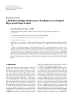
Figure 3: Impact of fading correlation on surviving symbol selection in M-algorithm (QPSK modulation is assumed).
is repeated for N
TX
N
SF
stages. Therefore, the total number
of branch metric calculations is reduced from 2
N
R
N
TX
N
SF
,
which is required for full MLD, to M2
N
R
N
TX
N
SF
by using
the proposed MLD. Finally, the log likelihood ratio (LLR) for
each channel coded bit is calculated from the branch metrics
of the surviving symbol candidates at the last stage of the
M-algor ithm, and channel decoding is performed to recover
the transmit data sequences.
2.2. Symbol Ordering in Proposed MLD. In the description of
the proposed MLD in the previous subsection, we assumed
that the transmit symbols are ordered in s
all
so that the set
of the code-multiplexed symbols from the same transmit
antenna is located in the same neighborhood in (8). Thus,
the ((n
− 1)N
SF
+ b)th element of s
all
is the bth data symbol
transmitted from the nth transmit antenna. However, this
order can be arbitrarily changed at the receiver by exchanging
the corresponding columns in matrix
F.Asisdescribedin
[12, 13], the ordering (ranking) of the symbols in which
stage each symbol appears fi rst affects the achievable PER
of quasi-MLD based on the M-algorithm greatly since the
M-algorithm successively reduces the number of symbol
candidates stage-by-stage from the symbols mapped to
the bottom of the transmit symbol vector. Therefore, we
investigate the following two symbol ordering strategies for
the proposed MLD.
2.2.1. Antenna-First Orderi ng Method. The received signal
power used for the selection of the surv iving symbol
candidates for the lth ordered symbols (thus, (N
TX
N
SF
−
l +1)thelementofs
all
) at the k (k ≥ l)-th stage of the
M-algorithm is the sum of the square of the elements from
N
TX
N
SF
− k + 1 to the (N
TX
N
SF
)th row at the (N
TX
N
SF
−
l +1)thcolumnof R. Therefore, the probability of false
discard of the correct symbol candidates is greater at an
earlier stage. The symbol ordering based on the received
signal power or signal-to-interference and noise power ratio
(SINR) of each symbol are presented in [12, 13] for the
OFDM case without spreading and code multiplexing. A
symbol in good condition is set to be tested from an earlier
stage. We call this method antenna-first ordering in the paper.
It should be noted that since the received signal power of all
code-multiplexed symbols from the same transmit antenna
are the same assuming that each element of the spreading
code matrix has the same power (this is true, e.g., in DFT
and Walsh-Hadamard matrices), the antenna-first ordering
method orders the symbols so that the set of the code-
multiplexed symbols from each transmit antenna is block-
wisedasin(8). Assuming that the transmitter antenna
branch indexes are arranged from the one with the smallest
received signal power in increasing order, let f (n) be the
transmitter antenna branch index ranked at the nth order.
Then, the (( f (n)
−1)N
SF
+b)th column vector of the original
form of F in (12) is moved to the ((n
− 1)N
SF
+ b)th column
in the antenna-first ordering, so that the bth data symbol
transmitted from the f (n)th transmit antenna becomes the
((n
− 1)N
SF
+ b)th element of s
all
. The resultant F and s
all
are
represented, respectively , as
F
=
⎡
⎢
⎢
⎢
⎢
⎢
⎢
⎢
⎢
⎢
⎢
⎢
⎢
⎢
⎢
⎣
h
1,1, f (1)
w
t
1
··· h
1,1, f (N
TX
)
w
t
1
.
.
.
.
.
.
.
.
.
h
1,N
RX
, f (1)
w
t
1
··· h
1,N
RX
, f (N
TX
)
w
t
1
.
.
.
h
N
SF
,1, f (1)
w
t
N
SF
··· h
N
SF
,1, f (N
TX
)
w
t
N
SF
.
.
.
.
.
.
.
.
.
h
N
SF
,N
RX
, f (1)
w
t
N
SF
··· h
N
SF
,N
RX
, f (N
TX
)
w
t
N
SF
⎤
⎥
⎥
⎥
⎥
⎥
⎥
⎥
⎥
⎥
⎥
⎥
⎥
⎥
⎥
⎦
, (18)
s
all
=
s
t
f
(
1
)
s
t
f
(
2
)
··· s
t
f
(
N
TX
)
t
. (19)
2.2.2. Code-First Ordering Method. The accuracy of the
surviving symbol candidates is in general degraded in the
M-algorithm for the combination of transmitted symbols
with a high fading correlation. This is because multiple
symbol candidates may have very similar branch metrics
6 EURASIP Journal on Advances in Signal Processing
(similar squared Euclidian distances to the received signal
point) in this case as shown in Figure 3.
In OFDM MIMO multiplexing with the frequency
domain spreading and code multiplexing, the fading correla-
tion among code-multiplexed symbols transmitted from the
same transmit antenna is one. To see clearly the shape of the
matrix R with the antenna-first ordering, let us assume flat
fading here such as H
1
= H
2
= = H
N
SF
. In this case, (n −
1)N
SF
+1 tonN
SF
th column vectors of matrix F in the form of
(18) are orthogonal to each other since W is a unitary matrix,
and every N
SF
th column vector has correlation. Therefore,
matrix R with the antenna-first ordering is represented as
R =
⎡
⎢
⎢
⎢
⎢
⎢
⎢
⎣
diag
λ
1,1
diag
λ
1,2
diag
λ
1,3
···
diag
λ
1,N
TX
0 diag
λ
2,2
diag
λ
2,3
···
diag
λ
2,N
TX
.
.
.
.
.
.
0 diag
λ
N
TX
−1,N
TX
−1
diag
λ
N
TX
−1,N
TX
0 0 diag
λ
N
TX
,N
TX
⎤
⎥
⎥
⎥
⎥
⎥
⎥
⎦
, (20)
where diag {λ
x,y
} is the N
SF
× N
SF
-dimensional diagonal
matrix all of whose diagonal elements are λ
x,y
,andλ
x,y
is
dependent on the channel matrix. Thus, after orthogonal-
ization, the signal components of the transmit symbol of
interest appear only every N
SF
stages. This makes surviving
symbol replica selection inaccurate especially at an earlier
stage. Note that when the channel is frequency selective, all
of the upper triangular elements of matrix R, which are zero
in (20),cantakenonzerovalues.However,themagnitudeof
these elements is low with hig h fading correlation between
subcarriers.
Therefore, we propose code-first ordering, in which the
M-algor ithm first tests the set of symbols transmitted from
different transmitter antennas, which are spread by the N
SF
th
spreading code sequence
w
N
SF
, then moves to the set of
symbols spread by the (N
SF
− 1)th spreading code sequence
w
N
SF
−1
, and so on. The fading correlation between the
neighbor-ordered symbols in the code-first method is lower
than that for the transmit antenna-first ordering method.
In the code-first ordering, the ((n
− 1)N
SF
+ b)th column
vector of the original form of F in (12) is moved to the
((b
− 1)N
TX
+ n)th column, so that the b-th data symbol
transmitted from the nth transmit antenna becomes the
((b
− 1)N
TX
+ n)th element of s
all
. The resultant F and s
all
are represented, respectively, as
F
=
⎡
⎢
⎢
⎢
⎢
⎢
⎣
w
1,1
H
1
w
1,2
H
1
··· w
1,N
SF
H
1
w
2,1
H
2
w
2,2
H
2
.
.
.
.
.
.
.
.
.
w
N
SF
,1
H
N
SF
··· w
N
SF
,N
SF
H
N
SF
⎤
⎥
⎥
⎥
⎥
⎥
⎦
, (21)
s
all
=
s
1,1
s
2,1
··· s
N
TX
,1
s
1,2
s
2,2
··· s
N
TX
,N
SF
t
. (22)
Assuming flat fading such as H
1
= H
2
= ··· = H
N
SF
for
simplicity, (b
−1)N
TX
+1 to bN
TX
th column vectors of matrix
F in the form of (21) are correlated to each other, and all the
other combinations of column vectors are orthogonal since
W is a unitary matrix. Therefore, matrix R w ith the code-
first ordering is represented as
R
=
⎡
⎢
⎢
⎢
⎢
⎢
⎢
⎣
R
sub
00
0 R
sub
0
0 R
sub
0
.
.
.
0
00R
sub
⎤
⎥
⎥
⎥
⎥
⎥
⎥
⎦
, (23)
where R
sub
is the N
TX
× N
TX
-dimensional upper triangular
matrix. Thus, after orthogonalization, the signal components
of the transmit symbol of interest appear in consecutive N
TX
stages using the code-first ordering. This makes surviving
symbol replica selection accurate compared to the case with
the antenna-first ordering. Similar to the case with antenna-
first ordering, when the channel is frequency selective, all of
the upper triangular elements of matrix R, which are zero in
(23), can take nonzero values.
We note that the code-first ordering method c an addi-
tionally use the received signal power-based ordering with
secondary priority. In this case, the elements of s
all
are
arranged as
s
all
=
s
f (1),1
s
f (2),1
··· s
f (N
TX
),1
s
f (1),2
s
f (2),2
··· s
f (N
TX
),N
SF
t
.
(24)
The additional use of the received signal power-based
ordering in the code-first ordering method can further
improve the PER performance of the proposed MLD.
However, the gain by using the additional received signal
power-based ordering is expected to be small since the
symbols transmitted from the same antenna are dispersed
over s
all
anyway in the code-first ordering method to give
higher priority to reducing the fading correlation between
neighbor-ordered symbols.
3. Simulation Results
3.1. Simulation Parameters. The PER of the proposed MLD
is measured by computer simulation and compared to that
EURASIP Journal on Advances in Signal Processing 7
10
−3
10
−2
10
−1
10
0
0 5 10 15 20
Average PER
Average received E
b
/N
0
per antenna (dB)
Antenna-first ordering (fixed order)
Antenna-first ordering
Code-first ordering
Code-first ordering with received signal
power-based secondary ordering
Uncoded
(N
TX
, N
RX
) = (4, 4)
N
SF
= 16
16QAM
Proposed MLD, M
= 128
(a) Uncoded case
10
−3
10
−2
10
−1
10
0
0 5 10 15 20
Average PER
Average received E
b
/N
0
per antenna (dB)
Antenna-first ordering (fixed order)
Antenna-first ordering
Code-first ordering
Code-first ordering with received signal
power-based secondary ordering
Rate-3/4 turbo coded
(N
TX
, N
RX
) = (4, 4)
N
SF
= 16
16QAM
Proposed MLD, M
= 128
(b) Coded case
Figure 4: Comparison of symbol ordering methods.
for the conventional MMSE receiver. Table 1 summarizes
the simulation parameters. We assume DFT-spread OFDM,
thus the DFT sequence is used as the spreading code. The
number of subcarriers that equals the spreading factor, N
SF
,
is parameterized from 4 to 128. The subcarrier spacing is
set to 15 kHz. One packet comprises 14 OFDM symbols.
As the MIMO configuration, (N
TX
,N
RX
) of (2,2) and (4,4)
are tested. QPSK and 16QAM are assumed as the data
modulation scheme, and the r ate-1/2, 3/4, and 8/9 Turbo
codes generated by puncturing the rate-1/3 Turbo code with
the constraint length of 4 a re used as the channel code. The
packet error is assumed to be perfectly detected.
As a channel model, an exponentially decayed 6-path
block Rayleigh fading with the rms delay spread of 1 μsis
assumed where the fading correlation among the transmitter
antennas and receiver antennas is zero.
The channel estimation and noise power estimation at
the receiver are assumed to be per fect. The LLR calculation
method from the branch metrics of the surviving symbol
candidates at the last stage of the M-algorithm is based on
[13]. The Max-Log MAP (maximum a posteriori) decoding
with 8 iterations is used for the decoding of the Turbo code.
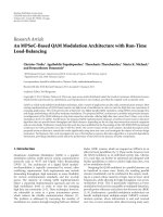
3.2. Simulation Results. Figures 4(a) and 4(b) show the
average PER of the proposed MLD with the antenna-first
ordering and code-first ordering methods as a function of
the average received signal energy per bit-to-noise spectrum
density ratio (E
b
/N
0
) for uncoded and coded cases, respec-
tively. The MIMO configuration (N
TX
,N
RX
) is (4,4) and N
SF
Table 1: Simulation parameters.
Parameter Value
Modulation DFT-spread OFDM
N
SF
(= number of
subcarriers)
4, 8, 16, 32, 64, and 128
Subcarrier spacing 15 kHz
(N
TX
, N
RX
) (2, 2) and (4, 4)
Data modulation QPSK, 16QAM
Channel coding
Turbo cod e (R
= 1/2, 3/4, and 8/9)/Max-
Log MAP decoding
Packet length 14 OFDM symbols
Channel model
Exponentially decayed 6-path Rayleigh
fading
(rms delay spread
= 1 μs, No fading
correlation between antennas)
Channel estimation Ideal
is 16. 16QAM is used and the rate-3/4 Turbo code is assumed
for the coded case. The number M of the surviving symbol
candidates for each stage of the M-algorithm is set to 128.
As a reference, the antenna-first ordering with fixed antenna
order (thus received signal power-independent) is also tested.
The PER with code-first ordering with additional use of
the received signal power-based ordering is also shown. The
effect of adaptive ordering based on the received signal power
is observed in the antenna-first ordering method. However,
8 EURASIP Journal on Advances in Signal Processing
10
−3
10
−2
10
−1
10
0
0 5 10 15 20 25 30 35
Average PER
Average received E
b
/N
0
per antenna (dB)
MMSE
M = 1
M
= 4
M
= 16
M
= 64
M
= 128
M
= 512
M
= 4096
Uncoded
N
SF
= 16
16QAM
Proposed MLD
(code-first ordering)
2, 2
(
N
TX
,
N
RX
)
=
(, )
(a) (N
TX
, N
RX
) = (2, 2)
10
−3
10
−2
10
−1
10
0
0 5 10 15 20 25 30 35
Average PER
Average received E
b
/N
0
per antenna (dB)
MMSE
M = 1
M
= 4
M
= 16
M
= 64
M
= 128
M
= 512
M
= 4096
Proposed MLD
(code-first ordering)
Uncoded
(N
TX
, N
RX
) = (4, 4)
N
SF
= 16
16QAM
(b) (N
TX
,N
RX
) = (4, 4)
Figure 5: Average PER as a function of average received E
b
/N
0
(uncoded case).
Figures 4(a) and 4(b) show that the code-first ordering
method greatly improves the achievable PER compared to
the antenna-first ordering method. This result indicates
that in OFDM MIMO multiplexing with frequency domain
spreading and code multiplexing, decreasing the fading
correlation between neighbor-ordered transmitted symbols
is more important than increasing the received signal power
for improving the accuracy of the selection of the surviving
symbol candidates in the M-algorithm. Meanwhile in code-
first ordering, the additional secondary ordering based on
the received signal power does not significantly improve
the PER. This is because the symbols transmitted from the
same antenna are dispersed over the transmit symbol vector
anyway in the code-first ordering method to give higher
priority to the reduction in the fading correlation between
neighbor-ordered symbols. When we compare Figures 4(a)
and 4(b), the PER improvement by using the code-first
ordering in the coded case is larger than that in the uncoded
case. This may indicate that the code-first ordering is effective
not only for detecting the ML symbol vector that has
least accumulated branch metric but also for finding the
other symbol vectors that have relatively low accumulated
branch metrics, which is important for calculating an
accurate LLR for the coded bits. In the following evaluation,
the code-first ordering method is used for the proposed
MLD.
Figures 5(a) and 5(b) show the average PER for the
uncoded case as a function of the average received E
b
/N
0
for (N
TX
,N
RX
) of (2,2) and (4,4), respectively. 16QAM is
assumed. The number of subcarriers, which is equal to
N
SF
, is set to 16. In the proposed MLD, the number
M of the surviving symbol candidates for each stage of
the M-algorithm is parameterized from 1 to 4096. For
comparison, the PER of the conventional MMSE receiver is
also plotted. In Figure 5(a), the required average received
E
b
/N
0
for the average PER of 10
−2
is significantly reduced
according to the increase in the M value. This is because the
number of false discards of the correct symbol candidates
can be decreased by increasing the M value. We find,
nevertheless, that the reduction in the required average E
b
/N
0
is small by increasing the M value beyond 16. When M is
16, the required average received E
b
/N
0
for the average PER
of 10
−2
is reduced by approximately 15 dB compared to the
case with conventional MMSE-based filtering. Regarding the
computational complexity, while the PER with full MLD
and the proposed MLD with M of 64 are expected to
be approximately identical, the number of branch metric
calculations is reduced from 2
N
R
N
TX
N
SF
≈ 3.4 × 10
38
,whichis
EURASIP Journal on Advances in Signal Processing 9
10
15
20
25
30
35
0 20 40 60 80 100 120
Average received E
b
/N
0
at average PER = 10
−2
(dB)
N
SF
= (number of subcarriers)
Uncoded
(N
TX
, N
RX
) = (2, 2)
16QAM
M
= 128
Proposed MLD
(antenna-first ordering)
MMSE
M = 4
M
= 8
M = 16
M
= 32
M
= 64
M
= 128
Proposed MLD
(code-first ordering)
(a) (N
TX
,N
RX
) = (2, 2)
10
15
20
25
30
35
Average received E
b
/N
0
at average PER = 10
−2
(dB)
N
SF
= (number of subcarriers)
M
= 128
Proposed MLD
(antenna-first ordering)
MMSE
M = 4
M
= 8
M = 16
M
= 32
M
= 64
M
= 128
0 8 16 24 32 40 48 56 64
Proposed MLD
(code-first ordering)
Uncoded
(N
TX
, N
RX
) = (4, 4)
16QAM
(b) (N
TX
,N
RX
) = (4, 4)
Figure 6: Required average received E
b
/N
0
as a function of N
SF
(uncoded case).
required for full MLD, to M2
N
R
N
TX
N
SF
≈ 3.3 × 10
4
by using
the proposed MLD.
In Figure 5(b), approximately the same behavior in the
PER performance is observed for (N
TX
,N
RX
) of (4,4) as
for (2,2). However, as the number of spatially multiplexed
symbols is increased, the required M value for achieving a
near saturated PER is increased (to approximately 64). Since
the proposed MLD achieves receiver antenna diversity that
is different from that when using the conventional MMSE
receiver, the reduction in the required average received E
b
/N
0
for the average PER of 10
−2
by using the proposed MLD with
M of 64 compared to the conventional MMSE-based filtering
is increased to approximately 22 dB for (N
TX
, N
RX
) of (4, 4).
Figures 6(a) and 6(b) show the required average received
E
b
/N
0
for the average PER of 10
−2
as a funct ion of N
SF
for
(N
TX
,N
RX
) of (2,2) and (4,4), respectively. 16QAM and no
channel coding are assumed. In the proposed MLD, M is
parameterized from 4 to 128. For comparison, the required
average received E
b
/N
0
of the conventional MMSE receiver
and that of the proposed MLD with antenna-first ordering
and M of 128 are also plotted. The reason why the required
average received E
b
/N
0
of the conventional MMSE receiver
is decreased according to the increase in N
SF
(= number
of subcarriers) is the increased frequency diversity. Mean-
while, the performance improvement due to the increased
frequency diversity is small in the proposed MLD especially
for (N
TX
, N
RX
) of (4, 4). This is because the proposed
MLD achieves receiver diversity; therefore, the additional
diversity gain via frequency diversity is small. Furthermore,
as N
SF
increases, the number of false discards of the correct
symbol candidates is increased in the M-algorithm of the
proposed MLD especially at the earlier stages since the signal
energy per stage is reduced as the number of stages in the
M-algorithm is proportional to the N
SF
value. However, even
in a relatively large N
SF
case such as 64, the proposed MLD
with the M of 128 can reduce the required average received
E
b
/N
0
for the average PER of 10
−2
by approximately 17.5 dB
compared to the conventional MMSE receiver. We can also
see that the performance enhancement by using the code-
first ordering method compared to the antenna-first one is
more significant as N
SF
decreases. This is because w hen N
SF
is
small, average fading correlation between H
i
becomes larger.
Figures 7(a) and 7(b) show the average PER assuming
rate-3/4 Turbo coding as a function of the average received
E
b
/N
0
for (N
TX
, N
RX
) of (2, 2) and (4, 4), respectively, with
M as a parameter. N
SF
is set to 16. 16QAM is assumed. For
comparison, the PER of the conventional MMSE receiver is
also plotted. Compared to the uncoded case shown in Figures
5(a) and 5(b), the PER performance both for the proposed
MLD and conventional MMSE receivers is improved. Since
10 EURASIP Journal on Advances in Signal Processing
10
−3
10
−2
10
−1
10
0
0 5 10 15 20 25 30
Average PER
Average received E
b
/N
0
per antenna (dB)
MMSE
M = 1
M
= 4
M = 16
M
= 64
M
= 128
M
= 512
M = 4096
Rate-3/4 turbo coded
(N
TX
, N
RX
) = (2, 2)
N
SF
= 16
16QAM
Proposed MLD
(code-first ordering)
(a) (N
TX
,N
RX
) = (2, 2)
10
−3
10
−2
10
−1
10
0
0 5 10 15 20 25 30
Average PER
Average received E
b
/N
0
per antenna (dB)
MMSE
M = 1
M
= 4
M = 16
M
= 64
M
= 128
M
= 512
M = 4096
Rate-3/4 turbo coded
(N
TX
, N
RX
) = (4, 4)
N
SF
= 16
16QAM
Proposed MLD
(code-first ordering)
(b) (N
TX
,N
RX
) = (4, 4)
Figure 7: Average PER as a function of average received E
b
/N
0
(coded case).
theconventionalMMSEreceiverscanachievesomedegreeof
diversity gain during the channel decoding, the performance
improvement of the conventional MMSE receivers is larger
than that of the proposed MLD receiver. As a result, the PER
reduction effect by using the proposed MLD compared to
the conventional MMSE receiver is decreased when channel
coding is applied. However, the required average received
E
b
/N
0
for the average PER of 10
−2
is still significantly
reduced when the proposed MLD is assumed due to the
large receiver antenna diversity gain even with the channel
coding. When M is 128, the required average received E
b
/N
0
for the average PER of 10
−2
is reduced by approximately
9 dB compared to the case with conventional MMSE-based
filtering for (N
TX
,N
RX
) of (2,2). Since the proposed MLD
achieves receiver antenna diversity that is different from that
when using the conventional MMSE receiver, the reduction
in the required average received E
b
/N
0
for the average PER of
10
−2
by using the proposed MLD with M of 128 compared
to the conventional MMSE-based filtering is increased to
approximately 1 2 dB for (N
TX
, N
RX
) of (4, 4). The required
M value for achie ving a near saturated PER in OFDM
MIMO multiplexing with frequency domain spreading and
code multiplexing is larger than that for OFDM MIMO
multiplexing without spreading, for example, in [12, 13].
This is because the use of the code multiplexing increases
the number of symbol candidates to be tested. Furthermore,
the use of the code multiplexing also increases the number of
stages in the M-algorithm from N
TX
to N
TX
N
SF
, which results
in reduced signal energy per stage.
Figures 8(a) and 8(b) show the required average received
E
b
/N
0
for the average PER of 10
−2
assuming rate-3/4 Turbo
coding as a function of N
SF
for (N
TX
, N
RX
)of(2,2)and(4,
4), respectively. 16QAM is assumed. In the proposed MLD,
M is parameterized from 16 to 512. For comparison, the
required average received E
b
/N
0
of the conventional MMSE
receiver and that of the proposed MLD with antenna-first
ordering and the M of 128 are also plotted. Basically the same
performance tendency is observed as in Figures 6(a) and
6(b). Although the number of false discards of the correct
symbol candidates is increased in the M-algorithm of the
proposed MLD as N
SF
increases, even in a relatively large
N
SF
case such as 64, the proposed MLD with the M of
128 can reduce the required average received E
b
/N
0
for the
average PER of 10
−2
by approximately 5 dB compared to the
conventional MMSE receiver for (N
TX
, N
RX
) of (4, 4).
Figures 9(a)–9(d) show the average PER assuming var-
ious modulation and channel coding rates as a function of
the average received E
b
/N
0
,withM as a parameter. Figures
9(a) and 9(b) assume QPSK data modulation with the Turbo
code rate of 1/2 and 8/9, respectively. Figures 9(c) and
EURASIP Journal on Advances in Signal Processing 11
5
10
15
20
25
30
0 20406080100120
Average received E
0
/N
0
at average PER = 10
−2
(dB)
N
SF
= (number of subcarriers)
MMSE
M = 128
M = 16
M
= 32
M
= 64
M = 128
M = 256
M = 512
Proposed MLD
(antenna-first ordering)
Rate-3/4 turbo coded
(N
TX
, N
RX
) = (2, 2)
16QAM
Proposed MLD
(code-first ordering)
(a) (N
TX
,N
RX
) = (2, 2)
5
10
15
20
25
30
Average received E
0
/N
0
at average PER = 10
−2
(dB)
N
SF
= (number of subcarriers)
MMSE
M = 128
M = 16
M
= 32
M
= 64
M = 128
M = 256
M = 512
Proposed MLD
(antenna-first ordering)
0 8 16 23 32 40 48 56 64
Rate-3/4 turbo coded
(N
TX
, N
RX
) = (4, 4), 16QAM
Proposed MLD
(code-first ordering)
(b) (N
TX
,N
RX
) = (4, 4)
Figure 8: Required average received E
b
/N
0
as a function of N
SF
(coded case).
9(d) assume 16QAM data modulation with the Turbo code
rate of 1/2 and 8/9, respectively. The MIMO configuration
(N
TX
,N
RX
) is (4,4) and N
SF
is 16. For comparison, the PER
of the conventional MMSE receiver is also plotted. From
Figure 9(a), we see that the gain in the required E
b
/N
0
for the average PER of 10
−2
by using the proposed MLD
compared to the conventional MMSE receiver is not so
significant when QPSK modulation w ith the Turbo code
rate of 1/2 is assumed. This is because the use of QPSK
reduces the operating point of the average received E
b
/N
0
,
which reduces the diversity gain by using the MLD-based
signal detection, and the use of a lower coding rate along
with channel coding across the transmitter antenna mitigates
the degraded diversity gain in the MMSE-based filtering
during the channel decoding process. This also explains the
reason why the PER with the conventional MMSE-based
filtering is more dependent on the coding rate than that with
the proposed MLD-based detection. However, we also see
that the gain of the proposed MLD over the conventional
MMSE-based filtering is enhanced according to the use of
the higher order modulation and coding rate. This means
that the proposed MLD is effective in achieving a very high
frequency efficiency by using MIMO multiplexing with a
high-order modulation and coding rate for OFDM with
frequency domain spreading and code multiplexing, similar
to the case with OFDM without spreading [21, 22].
We evaluate the computational complexity of the pro-
posed MLD from the viewpoint of the required number of
real multiplications per symbol. Table 2 gives the required
number of real multiplications per symbol. For compari-
son, the computational complexity levels of the full MLD
and the MMSE-based filtering are also evaluated. For all
methods, the computational complexity required for the
time/frequency synchronization a nd channel estimation are
not taken into account since they are common to all methods
and the complexity of these processes is largely dependent
on the applied algorithms. In Table 2, we assume that N
TX
is equal to N
RX
and they are denoted as N
ANT
= N
TX
=
N
RX
.TermC, which represents the number of constellation
points, is equal to 2
N
R
;thusC is 4 and 16, for QPSK and
16QAM, respectively. From the table, the proposed MLD can
significantly reduce the computational complexity more than
the full MLD, assuming N
ANT
= 4, C = 16, N
SF
= 16, and M =
128. The computational complexity of the proposed MLD is
approximately 70 times higher than that for the conventional
MMSE-based filtering. From the table, the computational
complexity of the proposed MLD is dominated by the
QR decomposition of the matrix F and the calculation
of the squared Euclidian distances although the number
of squared Euclidian distance calculations is significantly
reduced compared to the full MLD. Therefore, for further
study, we can consider two approaches to reduce further
12 EURASIP Journal on Advances in Signal Processing
10
−3
10
−2
10
−1
10
0
Average PER
Average received E
b
/N
0
per antenna (dB)
−50 51015
MMSE
M = 1
M
= 4
M
= 16
M
= 64
M
= 128
M
= 512
M
= 4096
Proposed MLD
(code-first ordering)
Rate-1/2 turbo coded
(N
TX
, N
RX
) = (4, 4)
N
SF
= 16
QPSK
(a) QPSK, rate-1/2 Turbo coded
10
−3
10
−2
10
−1
10
0
Average PER
Average received E
b
/N
0
per antenna (dB)
−50 5 101520
MMSE
M
= 1
M
= 4
M
= 16
M
= 64
M
= 128
M
= 512
M
= 4096
Proposed MLD
(code-first ordering)
Rate-8/9 turbo coded
(N
TX
, N
RX
) = (4, 4)
N
SF
= 16
QPSK
(b) QPSK, rate-8/9 Turbo coded
10
−3
10
−2
10
−1
10
0
Average PER
Average received E
b
/N
0
per antenna (dB)
MMSE
M
= 1
M
= 4
M
= 16
M
= 64
M
= 128
M
= 512
M
= 4096
Proposed MLD
(code-first ordering)
Rate-1/2 turbo
coded
(N
TX
, N
RX
) = (4, 4)
N
SF
= 16
16QAM
0 5 10 15 20 25 30
(c) 16QAM, rate-1/2 Turbo coded
10
−3
10
−2
10
−1
10
0
Average PER
Average received E
b
/N
0
per antenna (dB)
MMSE
M
= 1
M
= 4
M
= 16
M
= 64
M
= 128
M
= 512
M
= 4096
0 5 10 15
20 25 30
Proposed MLD
(code-first ordering)
Rate-8/9 turbo
coded
(N
TX
, N
RX
) = (4, 4)
N
SF
= 16
16QAM
(d) 16QAM, rate-8/9 Turbo coded
Figure 9: Average PER as a function of average received E
b
/N
0
for various modulation schemes and coding rates.
EURASIP Journal on Advances in Signal Processing 13
Table 2: Number of real multiplications per symbol required for signal detection.
Signal detection method Process
Required number of real
multiplications
Example: N
ANT
= 4,
C
= 16, N
SF
= 16, M = 128
Full MLD
FFT 4N
ANT
N
SF
log
2
N
SF
1,024
Generation of symbol replica candidates 4N
ANT
2
CN
SF
2
262,144
Calculation of squared Euclidian distances 2N
ANT
C
N
ANT
N
SF
N
SF
1.482 × 10
79
Total 1.482 × 10
79
MMSE-based filtering
FFT 4N
ANT
N
SF
log
2
N
SF
1,024
MMSE weight generation 12N
ANT
3
N
SF
12,288
MMSE weight multiplication 4N
ANT
2
N
SF
1,024
Despreading 4N
ANT
N
SF
2
4,096
Calculation of squared Euclidian distances 2N
ANT
CN
SF
2,048
Total 20,480
Proposed MLD
FFT 4N
ANT
N
SF
log
2
N
SF
1,024
Generation of matrix F 4N
ANT
N
SF
2
4,096
QR decomposition of matrix F 4N
ANT
3
N
SF
3
+8N
ANT
2
N
SF
2
1,081,344
Multiplication of Q
H
to received signal vector 4N
ANT
2
N
SF
2
16,384
Generation of symbol replica candidates
4(N
ANT
N
SF
(N
ANT
N
SF
+1)/2)C
133,120
Calculation of squared Euclidian distances 2N
ANT
CN
SF
M 262,144
Total 1,498,112
the computational complexity of the proposed MLD. The
first one is complexity reduction in the QR decomposition
of the matrix F. By utilizing the special structure of matrix
F, there is a possibility to reduce the calculation cost of
the QR decomposition (we assume that the inner product
calculation in the Gram-Schmidt orthogonalization can be
simplified). The second approach is to reduce the complexity
in the calculation of the squared Euclidian distances. For
example, by applying the method described in [22–24],
the computational complexity of the process for squared
Euclidian distance calculations will be reduced without PER
performance degradation.
Figure 10 shows the required number of real multiplica-
tions for different modulation schemes with the Turbo code
rate of 3/4 as a function of the required average received
E
b
/N
0
for the average PER of 10
−2
. The MIMO configuration
(N
TX
, N
RX
) is ( 4, 4) and N
SF
is 16. The relationship between
the required number of real multiplications and required
average received E
b
/N
0
in the proposed MLD is varied by
changing the M value. We see that the proposed MLD can
reduce the required average received E
b
/N
0
for the average
PER of 10
−2
for 16QAM with the rate-3/4 Turbo code by
approximately 12 dB compared to the conventional MMSE
receiver at the cost of a 70 times higher computational
complexity.
4. Conclusion
This paper presented a new MLD-based signal detection
method for OFDM MIMO multiplexing with frequency
domain spreading and code multiplexing. The proposed
MLD-based signal detection method is based on the QRD-M
algorithm (or QRM-MLD) for OFDM MIMO multiplexing,
which uses per subcarrier-based signal orthogonalization
and the computationally efficient M-algorithm to decom-
pose the spatially multiplexed transmit symbols. However,
the proposed MLD receiver jointly considers all the subcarri-
ers to which the spread symbols are mapped and constructs
the overall frequency-domain linear t ransformation matrix
which is a product of the space and frequency-domain
channel matrix and spreading code matrix in order to
decompose fully the spatial and code multiplexed transmit
symbols at the receiver. The QR decomposition of the
overall frequency-domain linear transformation matrix is
performed to derive the orthogonalized received signal vec-
tor. Then, the M-algorithm is used to achie ve computation-
ally efficient quasi-MLD with the orthogonalized received
signal vector. Furthermore, we showed that when frequency
domain spreading and code multiplexing are used in OFDM,
the symbol ordering for sequential signal detection based
on the fading correlation among the transmitted symbols,
which we call code-first ordering, significantly improves the
achievable PER performance. Simulation results showed that
when the spreading factor and number of code multiplexed
symbols a re 16, the proposed MLD reduces the required
average received E
b
/N
0
for the average PER of 10
−2
by
approximately 9 and 12 dB compared to the conventional
MMSE-based filtering for 2-by-2 and 4-by-4 MIMO multi-
plexing, respectively (16QAM with the rate-3/4 Turbo code
is assumed).
Acknowledgment
The authors would like to thank the reviewers for their
insightful and constructive suggestions.
14 EURASIP Journal on Advances in Signal Processing
10
3
10
4
10
5
10
6
10
7
10
8
−4 0 4 8 12 16 20 24 28
Number of real multiplications
Average received E
b
/N
0
at average PER = 10
−2
(dB)
QPSK, rate-3/4 turbo coded
Proposed MLD (code-first ordering)
MMSE
Proposed MLD (code-first ordering)
MMSE
16QAM, rate-3/4 turbo coded
M
= 1
M
= 1
4096
4096
128
128
512
512
4
4
16
16
64
64
Full MLD for QPSK
(Num. of real mul.:
4.4
× 10
40
)
Full MLD for 16QAM
(Num. of real mul.: 1.5 × 10
79
)
(N
TX
, N
RX
) = (4, 4)
N
SF
= 16
Figure 10: Number of real multiplications as a function of required
average received E
b
/N
0
.
References
[1] 3GPP TS36.300, “Evolved Universal Ter restrial Radio Access
(E-UTRA) and Evolved Universal Terrestrial Radio Access
Network (E-UTRAN),” Overall description.
[2] N. Yee, J P. Linnartz, and G. Fettweis, “Multi-carrier CDMA
in indoor wireless radio networks,” in Proceedings of the 4th
IEEE International Symposium on Personal, Indoor and Mobile
Radio Communications (PIMRC ’93), pp. 109–113, Yokohama,
Japan, September 1993.
[3] K. Fazel and L. Papke, “On the performance of convolutional-
coded CDMA/OFDM for mobile communication systems,”
in Proceedings of the 4th IEEE International Symposium on
Personal, Indoor and Mobile Radio Communications (PIMRC
’93), pp. 468–472, Yokohama, Japan, September 1993.
[4] S. Hara and R. Prasad, “Overview of multicarrier CDMA,”
IEEE Communications Magazine, vol. 35, no. 12, pp. 126–133,
1997.
[5] H. Atarashi, S. Abeta, and M. Sawahashi, “Broadband packet
wireless access appropriate for high-speed and high-capacity
throughput,” in Proceedings of the 53rd Vehicular Technology
Conference ( VTC ’01), vol. 1, pp. 566–570, Rhodos, Greece,
May 2001.
[6] Y. Wu, C. K. Ho, and S. Sun, “On some properties of Walsh-
Hadamard transformed OFDM,” in Proceedings of the 56th
Vehicular Technology Conference (VTC ’02), pp. 2096–2100,
Vancouver, Canada, September 2002.
[7] Y. Wang, X. Tao, P. Zhang, J. Xu, X. Wang, and T. Suzuki,
“MIMO-OFDM PAPR reduction by combining shifting and
inversion with matrix transform,” in Proceedings of the 18th
Annual IEEE International Symposium on Personal, Indoor and
Mobile Radio Communications (PIMRC ’07), Athens, Greece,
September 2007.
[8]D.Galda,H.Rohling,E.Costa,H.Haas,andE.Schulz,
“A low complexity transmitter structure for OFDM-FDMA
uplink systems,” in Proceedings of the 55th Vehicular Technology
Conference (VTC ’02), pp. 1737–1741, Birmingham, Ala, USA,
May 2002.
[9] R. Dinis, D. Falconer, C. T. Lam, and M. Sabbaghian, “A
multiple access scheme for the uplink of broadband wireless
systems,” in Proceedings of IEEE Global Telecommunications
Conference (GLOBECOM ’04), pp. 3808–3812, Dallas, Tex,
USA, December 2004.
[10] G. J. Foschini and M. J. Gans, “On limits of wireless com-
munications in a fading environment when using multiple
Antennas,” Wireless Personal Communications,vol.6,no.3,pp.
311–335, 1998.
[11] A. van Zelst, R. van Nee, and G. A. Awater, “Space division
multiplexing (SDM) for OFDM systems,” in Proceedings of the
51st IEEE Vehicular Technology Conference (VTC ’00), vol. 2,
pp. 1070–1074, Tokyo, Japan, May 2000.
[12] K. J. Kim, J. Yue, R. A. Iltis, and J. D. Gibson, “A QRD-
M/Kalman filter-based detection and channel estimation
algorithm for MIMO-OFDM systems,” IEEE Transactions on
Wireless Communications, vol. 4, no. 2, pp. 710–721, 2005.
[13] H. Kawai, K. Higuchi, N. Maeda et al., “Likelihood function
for QRM-MLD suitable for soft-decision turbo decoding and
its perfor m ance for OFCDM MIMO multiplexing in multi-
path fading channel,” IEICE Transactions on Communications,
vol. E88-B, no. 1, pp. 47–57, 2005.
[14] D. Reynolds and X. Wang, “Low-complexity turbo-equaliza-
tion for diversity channels,” Signal Processing,vol.81,no.5,
pp. 989–995, 2001.
[15] M. T
¨
uchler, R. Koetter, and A. C. Singer, “Turbo equalization:
principles and new results,” IEEE Transactions on Communica-
tions, vol. 50, no. 5, pp. 754–767, 2002.
[16] T. Abe and T. Matsumoto, “Space-time turbo equalization
in frequency-selective MIMO channels,” IEEE Transactions on
Vehicular Technology, vol. 52, no. 3, pp. 469–475, 2003.
[17] M. Sabbaghian and D. D. Falconer, “An analytical approach for
finite block length per formance analysis of turbo frequency-
domain equalization,” IEEE Transactions on Vehicular Technol-
ogy, vol. 58, no. 3, pp. 1292–1301, 2009.
[18] B. M. Hochwald and S. ten Brink, “Achieving near-capacity on
a multiple-antenna channel,”
IEEE Transactions on Communi-
cations, vol. 51, no. 3, pp. 389–399, 2003.
[19] S. B
¨
aro, J. Hagenauer, and M. Witzke, “Iterative detection of
mimo transmission using a list-sequential (LISS) detector,”
in Proceedings of International Conference on Communications
(ICC ’03), vol. 4, pp. 2653–2657, Anchorage, Alaska, USA, May
2003.
[20] S. Sun, Y. Dai, Z. Lei, H. Kenichi, and H. Kawai, “Pseudo-
inverse MMSE based QRD-M algorithm for MIMO OFDM,”
in Proceedings of the 63rd Vehicular Technology Conference
(VTC ’06), vol. 3, pp. 1545–1549, Melbourne, Australia, May-
July 2006.
[21] H. Taoka, K. Dai, K. Higuchi, and M. Sawahashi, “Field exper-
iments on MIMO multiplexing with peak frequency efficiency
of 50 bit/second/Hz using MLD based signal detection for
OFDM high-speed packet access,” IEEE Journal on Selected
Areas in Communications, vol. 26, no. 6, pp. 845–856, 2008.
[22] K. Higuchi, H. Kawai, H. Taoka, N. Maeda, and M . Sawahashi,
“Adaptive selection of surv iving symbol replica candidates for
quasi-maximum likelihood detection using M-algorithm with
EURASIP Journal on Advances in Signal Processing 15
QR-decomposition for OFDM MIMO Multiplexing,” IEICE
Transactions on Communications, vol. E92-B, no. 4, pp. 1258–
1271, 2009.
[23] H. Kawai, K. Higuchi, N. Maeda, and M. Sawahashi, “Adaptive
control of surviving symbol replica candidates in QRM-MLD
for OFDM MIMO multiplexing,” IEEE Journal on Selected
Areas in Communications, vol. 24, no. 6, pp. 1130–1140, 2006.
[24] B S. Kim and K. Choi, “A very low complexity QRD-M
algorithm based on limited tree search for MIMO systems,” in
Proceedings of the 67th Vehicular Technology Conference ( VTC
’08), pp. 1246–1250, Marina Bay, Singapore, May 2008.