báo cáo hóa học:" Research Article HIFSuite: Tools for HDL Code Conversion and Manipulation" ppt
Bạn đang xem bản rút gọn của tài liệu. Xem và tải ngay bản đầy đủ của tài liệu tại đây (940.12 KB, 20 trang )
Hindawi Publishing Corporation
EURASIP Journal on Embedded Systems
Volume 2010, Article ID 436328, 20 pages
doi:10.1155/2010/436328
Research Article
HIFSuite: Tools for HDL Code Conversion and Manipulation
Nicola Bombieri, Giuseppe Di Guglielmo, Michele Ferrari, Franco Fummi,
Graziano Pravadelli, Francesco Stefanni, and Alessandro Venturelli
ESD Group, Dipartimento di Informatica, Universit
`
a di Verona, Strada Le Grazie 15, 37134 Verona, Italy
Correspondence should be addressed to Nicola Bombieri,
Received 1 December 2009; Accepted 12 October 2010
Academic Editor: Chun Jason Xue
Copyright © 2010 Nicola Bombieri et al. This is an open access article distributed under the Creative Commons Attribution
License, which permits unrestricted use, distribution, and reproduction in any medium, provided the original work is properly
cited.
HIFSuite ia a set of tools and application programming interfaces (APIs) that provide support for modeling and verification
of HW/SW systems. The core of HIFSuite is the HDL Intermediate Format (HIF) language upon which a set of front-end
and back-end tools have been developed to allow the conversion of HDL code into HIF code and vice versa. HIFSuite allows
designers to manipulate and integrate heterogeneous components implemented by using different hardware description languages
(HDLs). Moreover, HIFSuite includes tools, which rely on HIF APIs, for manipulating HIF descriptions in order to support code
abstraction/refinement and postrefinement verification.
1. Introduction
The rapid development of modern embedded systems
requires the use of flexible tools that allow designers and veri-
fication engineers to efficiently and automatically manipulate
HDL descriptions throughout the design and verification
steps.
From the modeling point of view, nowadays, it is com-
mon practice to define new systems by reusing previously
developed components, that can be possibly modeled at
different abstraction levels such as transaction-level mod-
eling (TLM) and register-transfer level (RTL) by means of
different hardware description languages like VHDL, Sys-
temC, Verilog, and so forth. Such an heterogeneity requires
to either use cosimulation and coverification techniques
[1], or to convert different HDL pieces of code into an
homogeneous description [2]. However, cosimulation tech-
niques slow down the overall simulation, while manual
conversion from an HDL representation to another, as well
as manual abstraction/refinement from an abstraction level
to another, is not valuable solutions, since they are error-
prone and time consuming tasks. Thus, both cosimulation
and manual refinement reduce the advantages provided
by the adoption of a reuse-based design methodology.
To avoid such disadvantages, this paper presents HIFSuite,
a closely integrated set of tools and APIs for reusing already
developed components and verifying their integration into
new designs. Relying on the HIF language, HIFSuite allows
system designers to convert HW/SW design descriptions
from an HDL to a different HDL and to manipulate
them in a uniform and efficient way. In addition, from
the verification point of view, HIFSuite is intended to
provide a single framework that efficiently supports many
fundamental activities like transactor-based verification [3,
4], mutation analysis[5], automatic test pattern generation,
and so forth. Such activities generally require that designers
and verification engineers define new components (e.g.,
transactors), or modify the design to introduce saboteurs
[6], or represent the design by using mathematical models
like extended finite state machines (EFSMs) [7]. To the best
of our knowledge, there are no tools in the literature that
integrate all the previous features in a single framework.
HIFSuite is intended to fill in the gap.
The paper is organized as follows. Related work is
described in Section 2. An overview of the main features
of HIFSuite is presented in Section 3, while the HIF core-
language is described in Section 4. The HIF-based conversion
tools are presented in Section 5 while manipulation tools
2 EURASIP Journal on Embedded Systems
for modeling and verification are summarized in Section 6.
Section 7 reports some experimental results. Finally, remarks
concluding the paper are discussed in Section 8.
2. Related Work
The issue of automatic translation and manipulation of HDL
code has been addressed by different works.
VH2SC [8] is a translator utility from VHDL 87/93 to
SystemC. It is not able to handle large designs and presents
some known bugs. It is no more mantained and the author
himself suggests that it is not suited for industrial designs.
Another tool to automatically convert VHLD into Sys-
temC is VHDL-to-SystemC-Converter [9]. However, it is
limited only RTL synthesizable constructs.
Some approaches provide the capability of converting
HDL code into C++ to increase simulation performances. A
methodology to translate synthesizable Verilog into C++ has
been implemented in the VTOC [10] tool. The methodology
is based on synthesis-like transformations, which is able to
statically resolve almost all scheduling problems. Thus, the
design simulation switches from an event-driven to a cycle-
based-like algorithm.
VHDLC [11] is a VHDL to C++ translator, which aims
at fully VHDL’93 compiliance. The project is at alpha stage,
and thus, it is currently not suited for industrial applications.
The DVM [12] tool translates VHDL testbenches into
C++. Testbenches are encompassed into a small simulable
kernel which runs interconnected with the board. Running
native C++ code avoids the overhead introduced by using
an HDL simulator. Such a tool is restricted to only VHDL
testbenches.
Ve r i l a to r [ 13] is a Verilog simulator. It supports Verilog
synthesizable and some PSL SystemVerilog and Synthesis
assertions. To optimize the simulation, Verilator translates
the design into an optimized C++ code, wrapped by a
SystemC module. To achieve better performances, Verilator
performs semantics manipulations which are not standard
Verilog compliant. Thus, Verilator is meant to be used just as
asimulator.
FreeHDL [14] is a simulator for VHDL, designed to
run under Linux. The aim of the project is to create a
simulator usable also with industrial designs. To improve
performances, FreeHDL uses an internal tool, namely,
FreeHDL-v2cc, which translates the original VHDL design
into C++ code. Thus, FreeHDL presents limitations similar
to Verilator.
All previous approaches are not based on an intermediate
format, and they target only a point-to-point translation
from one HDL to another HDL or C++. Thus, manipulation
on the code before the translation is not supported. On
the contrary, some works have been proposed which use
an intermediate format to allow manipulation of the target
code for simplifying design manipulation and verification.
In this context, AIRE/CE [15], previously known as IIR, is
an Object-Oriented intermediate format. A front-end parser,
namely SAVANT, is available to translate VHDL designs
into such a language. By using AIRE/CE APIs it is possible
to develop verification and manipulation tools for VHDL
designs. In our previous work [16], we extend SAVANT
to allow the translation of VHDL designs into SystemC.
Unfortunatly, the AIRE/CE language is strictly tailored for
VHDL code, and thus, we experimented that it is not easy to
extend the SAVANT environment for supporting other HDLs
and particularly SystemC TLM.
To the best of our knowledge there is not a single compre-
hensive environment which integrates conversion capabili-
ties from different HDLs at different abstraction levels and
a powerful API to allow the development of manipulation
tool required during the refinement and verification steps of
a design.
The proposed HIF language has been designed to over-
come limits and restrictions of previous works. In particular,
HIF and the corresponding HIFSuite have been developed to
address the following aspects:
(1) supporting translation of several HDLs at both RTL
and TLM level,
(2) providing an object-oriented set of APIs for fast and
easy implementation of manipulation and verifica-
tion tools.
3. HIFSuite Overview
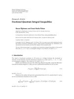
Figure 1 shows an overview of the HIFSuite features and
components. The majority of HIFSuite components have
been developed in the context of three European Projects
(SYMBAD, VERTIGO, and COCONUT). HIFSuite is com-
posed of the following
(i) An HIF core-language: It is a set of HIF objects
corresponding to traditional HDL constructs like,
for example, processes, variable/signal declarations,
sequential and concurrent statements, and so forth
(see Section 4).
(ii) Second is a set of front/back-end conversion tools
(see Section 5).
(a) HDL2HIF. It is front-end tools that parse
VHDL, Verilog and SystemC (RTL and TLM)
descriptions and generate the corresponding
HIF representations.
(b) HIF2HDL. It is back-end tools that convert HIF
models into VHDL, Verilog or SystemC (RTL
and TLM) code.
(iii) Third is a set of APIs that allow designers to develop
HIF-based tools to explore, manipulate, and extract
information from HIF descriptions (see Section 4.3).
The HIF code manipulated by such APIs can be
converted back to the target HDLs by means of
HIF2HDL.
(iv) Fourth is a set of tools developed upon the HIF
APIs that manipulate HIF code to support modeling
and verification of HW/SW systems, such as the
following.
EURASIP Journal on Embedded Systems 3
SystemC
Ve rilog
VHDL
SystemC
Ve rilog
VHDL
HDL2HIF:
front-end
conversion
tools
HIF2HDL:
back-end
conversion
tools
HIF
core-language
HIF APIs
Manipulation tools
ACIF:
saboteur
injector
TGEN:
transactor
generator
HIFSuite
EGEN:
EFSM
extractor
A2T :
RTL-to-TLM
abstractor
Figure 1: HIFSuite overview.
(a) EGEN: it is a tool developed upon the HIF
APIs that extracts an abstract model from HIF
code (Section 6.1). Such a tool, namely, EGEN,
automatically extracts EFSM models from HIF
descriptions. EFSMs represent a compact way
for modeling complex systems like, for example,
communication protocols [17], buses [18], and
controllers driving data-paths [19, 20]. More-
over, they represent an effective alternative to
the traditional finite state machines (FSMs) for
limiting the state explosion problem during test
pattern generation [21].
(b) ACIF: it is a tool that automatically injects
saboteurs into HIF descriptions (Section 6.2).
Saboteur injection is important to evaluate
dependability of computer systems [22]. In
particular, it is a key ingredient for verification
tools that relies on fault models like, for exam-
ple, automatic test pattern generators (ATPGs)
[23], tools that measure the property coverage
[24] or evaluate the quality of testbenches
through mutation analysis [25], and so forth.
(c) TGEN: it is a tool that automatically gen-
erates transactors (Section 6.3). Verification
methodologies based on transactors allow an
advantageous reuse of testbenches, properties,
and IP-cores in TLM-RTL-mixed designs, thus
guaranteeing a considerable saving of time
[26]. Moreover, transactors are widely adopted
for the refinement (and the subsequence ver-
ification) of TLM descriptions towards RTL
components [27].
(d) A2T: it is a tool that automatically abstracts
RTL IPs into TLM models. Even if transactors
allow designers to efficiently reuse RTL IPs
at transaction level, mixed TLM-RTL designs
cannot always completely benefit of the effec-
tiveness provided by TLM. In particular, the
main drawback of IP reuse via transactor is
that the RTL IP acts as a bottleneck of the
mixed TLM-RTL design, thus slowing down the
simulation of the whole system. Therefore, by
using A2T, the RTL IPs can be automatically
abstracted at the same transaction level of the
other modules composing the TLM design, to
preserve the simulation speed typical of TLM
without incurring in tedious and error-prone
manual abstraction [28, 29].
The main features of HIF core-language and HIF-based
tools are summarized in next sections.
4. HIF Core-Language and APIs
HIF is an HW/SW description language structured as a tree
of objects, similarly to XML. Each object describes a specific
functionality or component that is typically provided by
HDL languages like VHDL, Verilog, and SystemC. However,
even if HIF is quite intuitive to be read and manually written,
it is not intended to be used for manually describing HW/SW
systems. Rather, it is intended to provide designers with
a convenient way for automatically manipulating HW/SW
descriptions.
The requirements for HIF are manifold as it has to
represent the following
(i) system-level and TLM descriptions with abstract
communication between system components,
(ii) behavioral (algorithmic) hardware descriptions,
(iii) RTL hardware descriptions,
(iv) hardware structure descriptions,
(v) software algorithms.
4 EURASIP Journal on Embedded Systems
To meet these requirements, HIF includes several con-
cepts that are inspired by different languages. Concerning
RTL and behavioral hardware descriptions, HIF is very much
inspired to VHDL. On the other hand, some constructs
have been taken from C/C++ programming language for the
representations of algorithms (e.g., pointers and templates).
The combination of these different features makes HIF a
powerful language for HW/SW system representations.
4.1. HIF Basic Elements. HIF is a description language struc-
tured as a tree of elements, similarly to XML (see Figure 2).
It is very much like a classical programming language, that
is, a typed language which allows the definition of new types,
and includes operations like assignments, loops, conditional
executions, and so forth. In addition, since HIF is intended to
represent hardware descriptions, it also includes typical low-
level HDL constructs (e.g., bit slices). Finally, concerning the
possibility of structuring a design description, HIF allows the
definition of components and subprograms.
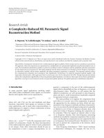
To look at similarities between HIF and traditional
HDLs, let us consider Figure 2. In Figure 2(a), a two-input
parameterized adder/subtractor VHDL design is shown,
while the corresponding HIF representation generated by
the front-end tool HDL2HIF (see Section 5) is depicted in
Figure 2(b).
As a special feature, HIF gives the possibility to add
supplementary information to language constructs in form
of so-called properties. A list of properties can be associated
to almost every syntactic constructs of the HIF language.
Properties allow designers to express information for which
no syntactic constructs are included in the HIF grammar, and
therefore they give a great flexibility to the HIF language. For
example, the fact that a signal has to be considered as a clock
signal can be expressed by adding a property signal
type
to the signal declaration as follows:
(SIGNAL s(BIT)(PROPERTY signal
type
clock)).
4.2. System Description by Using HIF. The top-level element
of a system represented by an HIF description is the SYSTEM
construct (see Figure 2(b)). It may contain the definition of
one or more libraries which define new data types, constants
and subprograms, and the description of design units.An
HIF description may also contain a list of protocols,which
describe communication mechanisms between design units.
Design units are modeled by DESIGNUNIT objects, which
define the actual components of the system. A design
unit may use types, constants and subprograms defined in
libraries included in the SYSTEM construct.
The same design unit can be modeled in different
ways inside the same system by using views.Forexample,
we can model different views of the same design unit
at different abstraction levels. Thus, a VIEW object is a
concrete description of a system component. It includes
the definition of an INTERFACE by which the component
communicates with the other parts of the system. Moreover,
a view may include libraries and local declarations. The
internal structure of a view is described in details by means of
the CONTENTS construct. To make a comparison with VHDL,
a view can be seen as a generalization of VHDL entity and
architecture.
An INTERFACE object gives the link between a design
unit and the rest of the system. An interface can contain ports,
and parameters.
A CONTENTS object can contain a list of local dec-
larations, a list of state tables, which describe sequential
processes, and a list of component instances and nets which
connect such instances. Furthermore, a CONTENTS object can
contain a set of concurrent actions (called GLOBALACTIONs),
that is, assignments and procedure calls which assign values
to a set of signals in a continuous manner.
4.2.1. Sequential Processes. In HIF, behaviors described by
sequences of statements (i.e., processes) are expressed by
state tables.ASTATETABLE object defines a process, whose
main control structure is an EFSM (see Section 6.1), and
the related sensitivity list. The state tables can describe syn-
chronous as well as combinational processes. The entry state
of the state machine can be explicitly specified. Otherwise,
the first state in the state list is considered as an entry state.
STATE objects included in the state table are identified by
a unique name and they are associated to a list of instructions
called actions (i.e., assignments, conditional statements, etc.)
to be sequentially executed when the HIF model is converted
into an HDL description for simulation.
4.2.2. Components Instances. Descriptions where one or
more components are instantiated and connected each other
are modeled by using the INSTANCE and the NET constructs.
An INSTANCE object describes an instance of a design unit.
More precisely, an
INSTANCE object refers to a specific view
of the instantiated design unit.
A NET object contains a list of port references. Nets are
used to express connectivity between interface elements of
different design unit instances (i.e., system components).
4.2.3. Concurrent Actions. They correspond to concurrent
assignments and concurrent procedure calls of VHDL, and
they are modeled by GLOBALACTION objects. Concurrent
assignments are used to assign a new value to the target
(which must be a signal or a port) each time the value of the
assignment source changes. Similarly, concurrent procedure
calls are used to assign a new value to signals mapped to the
output parameters each time one of the input parameters
changes its value.
4.2.4. Support for TLM Constructs. TLM is becoming a usual
practice for simplifying system-level design and architecture
exploration. It allows the designers to focus on the design
functionality while abstracting away implementation details
that will be added at lower abstraction levels. The HIF
language supports the SystemC TLM constructs provided
by OSCI [30], which mainly rely on C++ constructs such
as pointers and templates. Figure 3 shows a typical TLM
interface with socket channels for blocking and nonblocking
EURASIP Journal on Embedded Systems 5
addsub
a[4
··0]
b[4··0]
addnsub
result[5
··0]
LIBRARY ieee;
USE ieee.std
logic l164.ALL;
PACKAGE type
def pkg IS
CONSTANT ADDER
WIDTH : INTEGER := 5;
CONSTANT RESULT
WIDTH:INTEGER:= 6;
SUBTYPE ADDER
VALUE IS integer RANGE 0 TO 2
∗∗
ADDER WIDTH - 1;
SUBTYPE RESULT
VALUE IS integer RANGE 0 TO 2
∗∗
RESULT WIDTH - 1;
END type
def pkg;
LIBRARY ieee;
USE ieee.std
logic l164.ALL;
USE work.type
def pkg.ALL;
ENTITY addsub IS
PORT
(
a:IN ADDER
VALUE;
b:IN ADDER
VALUE;
addnsub:IN STD
LOGIC;
result:OUT RESULT
VALUE
);
END addsub;
ARCHITECURE rtl OF addsub IS
BEGIN
PROCESS(a,b,addnsub)
BEGIN
IF(eddnsub = ‘1’)THEN
result <
= a + b;
ELSE
result <
= a − b;
END IF;
END PROCESS;
END rtl;
(a)
(SYSTEM system
(LIBRARYDEF type def
(CONSTANT ADDER WIDTH (INTEGER)(INITIALVALUE 5))
(CONSTANT WIDTH (INTEGER)(INITlALVALUE 6))
(RANGE (UPTO 0 (- (POW 2 WIDTH) 1)) )))
(TYPEDEF RESULT VALUE (INTEGER
(TYPEDEF ADDER VALUE (INTEGER
(RANGE (UPTO 0 (- (POW 2 RESULT WIDTH) 1)) )))
)
(DESIGN UNIT addsub
(VIEW rtl
(VIEWTYPE "")
(DESIGN
(LIBRARY type def pkg Hif"")
(INTERFACE
(PORT a (IN)(TYPEREF VALUE))
(PORT b
(PORT addnsub (IN)(BIT (RESOLVED)))
(PORT (OUT)(TYPEREF RESULT VALUE))
)
(CONTENTS
(STATETABLE process
(SENSITIVITY a b addnsub)
(STATE process
(CASE
(ALT (= ddnsub ‘1’)
(ASSIGN result (+ a b))
)
(DEFAULT
(ASSIGN result (- a b))
)
)
)
)
)
)
)
)
pkg
RESULT
ADDER
HARDWARE)
ADDER
(IN)(TYPEREF VALUE))ADDER
result
(b)
Figure 2: (a) A VHDL design description. (b) The textual format of the corresponding HIF representation.
tlm generic payload trans;
tlm
target socket< WIDTH,
PROTOCOL > target
socket;
tlm
initiator socket< WIDTH,
PROTOCOL > init
socket;
(a)
(VARIABLE trans (TYPEREF tlm generic payload))
(VARIABLE target
socket
(TYPEREF tlm
target socket
(TYPETPASSIGN BUSWIDTH (TYPEREF WIDTH))
(TYPETPASSIGN TYPES (TYPERREF PROTOCOL))))
(VARIABLE init
socket)
(TYPEREF tlm
initiator socket
(TYPETPASSIGN BUSWIDTH (TYPEREF WIDTH))
(TYPETPASSIGN TYPES (TYPEREF PROTOCOL))))
(b)
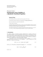
Figure 3: (a) Example of TLM interface with socket channels for blocking and nonblocking calls in SystemC. (b) The corresponding HIF
representation.
calls in SystemC and the corresponding HIF representa-
tion. The SystemC interface definition exploits nested C++
templates, which are preserved in the HIF description. The
HIF language provides two keywords to support templates:
TYPETP and TYPETPASSIGN. TYPETP is used for declaration
of objects of template type. Instead TYPETPASSIGN is used
for instantiation of template object as shown in Figure 3(b).
In HIF, the declaration of pointers is represented by using the
POINTER object as follows:
(POINTER type property).
4.3. HIF Application Programming Interfaces. HIFSuite pro-
vides the HIF language with a set of powerful C++ APIs
which allow to explore, manipulate, and extract information
from HIF descriptions. There are two different subsets in HIF
APIs: the HIF core-language APIs and the HIF manipulation
APIs.
4.3.1. HIF Core-Language APIs. Each HIF construct is
mapped to a C++ class that describes specific properties and
attributes of the corresponding HDL construct. Each class is
provided with a set of methods for getting or setting such
properties and attributes.
For example, each assignment in Figure 2(b) is mapped
to an AssignObject which is derived from ActionObject
(see Figure 4). This class describes the assignment of
6 EURASIP Journal on Embedded Systems
anexpressiontoavariable,aregister,asignal,aparameter,
or a port, and it has two member fields corresponding to the
left-hand side (target) and the right-hand side (source) of the
assignment.
The UML class diagram in Figure 4 presents a share of the
HIF core-language APIs class diagram. Object is the root of
the HIF class hierarchy. Every class in the HIF core-language
APIs has Object as its ultimate parent.
4.3.2. HIF Manipulation APIs. The HIF manipulation APIs
are used to manipulate the objects in HIF trees and they are
exploited by the tools described in Section 6.
The first step of any HIF manipulation consists of reading
the HIF description by the following function:
Object Hif ::File ::ASCII ::read
(const char filename).
This function loads the file and builds the corresponding
tree data structure in memory. An analogous writing func-
tion allows to dump the modified HIF tree on a file.
char Hif ::File ::ASCII ::write
(const char filename, Object obj).
Once the HIF file is loaded in memory, many APIs
are available to navigate the HIF description. The most
important are the following.
(i) Search Function. The search function finds the objects
that match a criteria specified by the user. It searches
the target objects starting from a given object until
it reaches the bottom (or the max depth) of the HIF
tree. For example, the search function can be used
to find out all variables that match the name state
starting from base
object, as in Algorithm 1.
(ii) Visitor Design Pattern. In object-oriented program-
ming and software engineering, the visitor design
pattern is generally adopted as a way for separating an
algorithm from an object structure. A practical result
of this separation is the ability to add new operations
to existing object structures without modifying these
structures. The visitor design pattern is very useful
when there is a tree-based hierarchy of objects and
it is necessary to allow an easy implementation of
new features to manipulate such a tree. The HIF
APIs provide visitor techniques in two forms: as
an interface which must be extended to provide
visitor operators, and as an apply() function. In
the first case, a virtual method is inserted inside the
HIF object hierarchy, which simply calls a specific-
implemented visiting method on the object passed as
parameter. The passed object is called visitor and it is
a pure interface. The programmer has to implement
such a visitor to visit and manage the HIF tree, by
defining the desired visiting methods. In contrast, the
apply() function is useful to perform a user-defined
function on all the objects contained in a subtree of a
HIF description. The signature for the apply function
is the following:
void Hif ::apply (Object o,char(f)
(Object ,void ),void data).
(iii) Compare Function. It provides designers with a way
to compare two HIF objects and the corresponding
subtrees. Its signature is the following:
static char compare (Object obj1,
Object obj2)
(iv) Object Replacement Function. It provides designers
with a way for replacing an object and its subtree with
adifferent object. Its signature is the following:
int Hif ::replace(Object from, Object
to)
4.4. HIF Semantics. Handling different HDLs that have
different semantics by using a single intermediate language
rises the importance of defining carefully a semantics for
such intermediate language. In particular, the definition
of a sound semantics is necessary for guaranteeing the
correctness of the conversion and manipulation tools.
We define a semantics for HIF that aims at supporting
the representation of RTL designs for the main important
and used HDLs (i.e., VHDL, Verilog, and SystemC) and the
representation of TLM designs.
The main differences among VHDL, Verilog, and Sys-
temC semantics that make hard the automatic conversion of
designs between them can be summarized as follows.
(i) Data Types. Not all the languages have the same type
management. Thus, the conversion between different
languages requires to make explicit (or to remove)
some cast or calls to type conversion functions.
(ii) Concurrent Assignments. The concurrent assignments
of VHDL and Verilog do not have a direct mapping
into a SystemC construct. They can be modeled in
SystemC by converting each concurrent assignment
into a concurrent process sensitive to the read signals
and ports.
(iii) Operators. The HDLs have different operators and
different types on which such operators are defined.
For example, VHDL uses the same operator symbol
for both logic and bitwise operators while Verilog and
SystemC have different symbols for them.
(iv) TLM Constructs. SystemC allows TLM descriptions
by using templates and pointers, while VHDL and
Verilog support only RTL descriptions.
(v) Variable Declaration and Scoping. The behavior of
variables and their scoping rules are diff
erent among
HDLs. For example, in VHDL variables declared
inside a process will retain the last assigned value
between two subsequent process executions. In Sys-
temC, a variable declared inside a process such as
SC
METHOD will get the initial value at each new
process invocation. To map the VHDL variable
semantics into the SystemC context, the variable
declaration should be moved outside the process and
inside the module interface.
EURASIP Journal on Embedded Systems 7
Object
BitObject
BoolObject
CharObject
EnumObject
IntObject
PointerObject
RealObject
TypeRefObject
ArrayObject
RecordObject
TypeObject
SimpleTypeObjectCompositeTypeObjectAssignObject
CaseObject
ExitObject
ForObject
IfObject
NextObject
PCallObject
ReturnObject
ActionObject
SwitchObject
WaitObject
WhileObject
Figure 4: A share of the HIF core language class diagram.
Hif : : hif query query;
query.set
object type(NameNode); //search for NameNode
query.set
name("state"); //search for string “state”
std : : list<Node
>
found object = Hif : : search(base object, query);
Algorithm 1: Example of search function usage.
(vi) Statements. Some programming techniques and
statements cannot be directly mapped into another
HDL. As an example, the SystemC pre- and postin-
crement operators are not valid in VHDL.
In this context, we analyzed different semantics to be
adopted for defining the HIF language.
(i) RTL HDL Specific Semantics. The semantics of an
already existing RTL HDL (i.e., the VHDL or Verilog
semantics) would be already well defined and well
known. Nevertheless, this choice would be a restric-
tive solution since such languages do not apply to
TLM descriptions.
(ii) SystemC Semantics. It would apply for both RTL
and TLM designs. Nevertheless, SystemC is a C++
library and, hence, its semantics corresponds to
the C++ semantics. It is not the best solution for
implementing the back-end tools, as they would
reduce the set of HIF constructs into the smaller set
of HDL RTL constructs.
(iii) Union Semantics. It is the semantics obtained from
the union of VHDL, Verilog and SystemC semantics.
This solution would allow both TLM and RTL
designs, and it also would simplify the translation
from an HDL to HIF. On the other hand, it would
require a greater effort for translating HIF descrip-
tions to HDL descriptions, as not all constructs have
an immediate mapping in every language.
(iv) Intersection Semantics. It is obtained from the inter-
section of the Verilog, VHDL and SystemC seman-
tics. It would simplify the translation from HIF to
8 EURASIP Journal on Embedded Systems
an HDL, as only constructs shared by all the HDLs
would belong to HIF. Nevertheless, this choice would
be too restrictive since only few RTL designs and no
TLM description would be supported.
(v) Dynamic Semantics. In this case HIF would not
have a predefined semantics. Instead, each HIF
description would keep track of the source HDL,
thus importing also the semantics of such HDL. This
choice simplifies the translation from an HDL to HIF,
but it implies a great effort in developing the back-
end tools. Moreover, the HIF descriptions would be
too complex for the manipulation tools since each
tool should have a different behavior according to the
design specific semantics.
For all these reasons, we have chosen to define the HIF
semantics as the VHDL semantics enriched to support TLM
constructs. The main advantages of such semantics are the
following.
(1) The intermediate language is strongly typed (like
VHDL).
(2) There is a simple RTL-to-RTL compatibility between
different HDLs. The fact that VHDL is strongly typed
makes easier to map its semantics into other HDL
semantics.
(3) It supports TLM.
5. Conversion Tools
In this section we report the main characteristics of the
conversion tools, by starting from an overview of the tool
structures and, then, by showing the translation semantics
such tools rely on.
5.1. The Front-End and Back-End Conversion Tools. The con-
version tools are organized into front-end (HDL2HIF)and
back-end (HIF2HDL) tool sets.
5.1.1. HDL2HIF. They convert HDL implementations into
HIF. HDL2HIF supports conversions from VHDL, Verilog,
and SystemC, which are implemented in the submodules
VHDL2HIF, VERILOG2HIF, and SC2HIF,respectively.
The VHDL2HIF and VERILOG2HIF tools have a com-
mon structure, which is composed of the following modules.
(a) First is a pre-parsing module, which performs basic
configuration operations and parameter parsing, and
which selects the output format (readable plain text
or binary).
(b)SecondisaparserbasedonGNUBison [31], which
directly creates an HIF-objects tree. The conversion
process is based on a recursive algorithm that exploits
a pre-ordered visit strategy on the syntax tree nodes.
(c) Third is a postconversion visitor, which refines the
generated HIF tree according to the input language.
(d) Fourth is a final routine, which dumps the HIF tree
on a file.
The SC2HIF tool has the structure composed of the
following modules:
(a) a preparsing module, which performs basic configu-
ration operations and parameter parsing, and which
selects the output format (readable plain text or
binary);
(b) a parser based on GNU Bison, which creates an
abstract syntax tree (AST) of the input code; such an
AST is composed of XML objects with dedicated tags;
(c) a core module, which converts the AST into an HIF-
object tree; The conversion process is based on a
recursive algorithm that exploits a preordered visit
strategy on the tree nodes;
(d) a postconversion visitor, which refines the generated
HIF tree;
(e) a final routine, which dumps the HIF tree on a file.
An intermediate XML tree has been preferred for trans-
lating SystemC descriptions to HIF as the SystemC language
is much more complex than other HDLs. The translation
requires different checks in order to perform a correct
mapping. This intermediate operation has been performed
by using KaSCPar [32], an open source tool which has been
improved to support TLM.
5.1.2. HIF2HDL. They convert HIF code back to VHDL
(HIF2VHDL), Verilog (HIF2VERILOG)orSystemC(HIF2
SC). The structure of HIF2HDL tools includes the following
modules.
(a) First is a preparsing module, which sets up the con-
version environment, performs basic configuration
operations, parses the parameters, and sets the output
language.
(b) Second is a set of refinement visitors, which perform
operations to allow an easier translation of HIF trees,
according to the output language. For instance, in
VHDL it is possible to specify the bit value 1 by
writing ‘1’. On the other hand, in SystemC, ‘1’
is interpreted as a character and, thus, a cast to the
sc
logic type is required. To solve this problem, a
visitor has been implemented to wrap the constant
object ‘1’ with an sc
logic cast object into the HIF
tree.
(c) Third is a module that dumps a partial conversion of
the HIF code into temporary files. Such a module has
been implemented to solve problems of consistency
between the order adopted to visit the HIF AST and
the order needed to print out the code in the target
language. To avoid many complex checks, the tools
firstly dump the output code directly in temporary
files and then they merge the content of temporary
files together in the correct order.
(d) Fourth is a postvisit module, which merges together
the temporary files and creates the final output.
EURASIP Journal on Embedded Systems 9
In the following subsections, we show how the imple-
mentation of most meaningful and critical HDL statements
is matched among VHDL, Verilog, and SystemC, and how
they are represented in HIF. The HIFSuite conversion
tools rely on these matching for converting designs among
different HDL languages.
5.2. HDL Types. Tab le 1 depicts the matching of the most
important HDL types. In this work, we consider all the
VHDL types implemented into the VHDL IEEE libraries
as native VHDL types (e.g., the VHDL std
logic vector
and std
logic which are defined inside the library
std
logic 1164 are considered native types).
In Table 1, the mapping of the Verilog types is not fully
specified. In fact, it is possible to know the correct mapping
into a reg or into a wire only during the conversion phase,
by checking if the corresponding identifier is used as a signal
or as a memory element.
Another issue about Verilog is that both resolved and
unresolved logic types are mapped into the same Verilog
constructs. This is forced by the fact that Verilog has only
resolved types.
For the INTEGER type, it is worth to note that, in HIF,
it is possible to specify a RANGE of values, the number of
bits on which is represented, whether it is signed or unsigned,
and whether the range is upto or downto (e.g., in VHDL a
natural has a different range from SystemC unsigned).
5.3. HDL Cast and Type Conversion Functions. Every HDL
language has three possible type conversion methods.
(i) Implicit Cast. The language allows to convert a gen-
eral type into another. The translation is thus auto-
matically performed by the compiler. As an example,
in SystemC it is possible to implicitly cast a char to
an int.
(ii) Explicit Cast. The language supports the type trans-
lation, even if it requires the designer to use a special
language construct (i.e., a cast).
(iii) Conversion Function. The language does not support
the type conversion and, thus, a manual conversion
is required. To simplify the designer’s task, many
predefined conversion functions are usually supplied
by supporting libraries (e.g., the VHDL IEEE library).
Since the HIF semantics is an extension of the VHDL
semantics, the HIF type conversion rules are inherited from
VHDL. As a consequence, since the implicit casts are not
allowed in VHDL, they are not allowed neither in HIF.
On the other hand, the explicit cast is represented by the
CAST object, while the conversion functions are mapped into
CONV objects. The set of conversion functions include all
the conversion functions implemented into the VHDL IEEE
library.
Ta ble s 2 and 3 report the matching of some cast and
conversion functions, when they are implemented in VHDL,
Verilog, and SystemC and how they are represented in HIF.
We assume the following.
(i) I is the generic expression on which the cast or con-
version is performed.
(ii) t
RANGE is a range as intended into the HIF syntax.
(iii) size is the size in bits needed to represent the values
in t
RANGE.
In Verilog there are only two casting directives
($signed() and $unsigned()), since it is a loosely typed
language. Thus, it requires only conversion tasks from signed
to unsigned types and vice versa.
5.4. HDL Operators. The HIF language has a VHDL-like
set of native operators with the exception that, in HIF, the
difference between logic and bitwise operators is preserved.
In addition, HIF has some operators that have not translation
into VHDL or Verilog, as they are related to TLM designs
(e.g., the pointer dereferencing operator, which is available
only in SystemC).
Ta ble 4 reports the matching among several operators.
The shift operator is a meaningful example of operator
conversion. The shift operator of Verilog is arithmetic if
the operand is signed; otherwise it is logic. In contrast, the
right shift semantics of C++ is platform dependent, since
the logic or arithmetic shift is not specified by the standard.
Thus, the mapping from SystemC to HIF is a platform-
dependent code, and the equivalence cannot be guaranteed
when converting HIF designs to SystemC. For this reasons, in
this case, warnings are raised to the users by the conversion
tools.
5.5. HDL Structural Statements. Tab le 5 shows how the
structural statements are matched among HDLs. Note 1
indicates that in HIF each design unit can have one or more
VIEW objects, each one containing one INTERFACE and one
CONTENTS object. In contrast, in VHDL, it is possible to
attach one or more architectures to a single interface. To
achievesuchbehaviorinHIF,wecreatemoreVIEW objects
each one having the same interface.
Note 2 is related to the description of a process into
different HDLs. For SystemC, there are three kinds of process
constructs (i.e., SC
METHOD, SC THREAD,andSC CTHREAD),
while HIF has only one type of processes (like VHDL). Thus,
during the conversion from and to SystemC, the conversion
tools recognize the SystemC process type and perform the
code analysis for the correct mapping.
Note 3 is related to the management of assignments.
There are two syntax for VHDL assignments (i.e., one for
signals and one for variables) and two assignment operators
in Verilog (i.e., blocking and continuous). In SystemC, a
single assignment applies for both signals and variables.
Notes 4 and 5 are related to constructs FORGENERATE
and IFGENERATE. They are typical of VHDL and Verilog
languages while they have not a corresponding native con-
struct in SystemC. Their conversion is achieved by inserting
a loop (or a conditional statement) into the SystemC module
constructor.
Note 6 is related to the syntax mapping for a variable
declaration. In this case, a simple syntax-based translation
10 EURASIP Journal on Embedded Systems
Table 1: Matching of HDL types.
HIF VHDL SystemC Verilog
BIT bit sc bit wire or reg
BOOLEAN boolean bool wire or reg
CHAR char char
INTEGER integer int integer
(ARRAY (PACKED) (INTEGER) (OF (BIT)) (RANGE)) bit
vector (RANGE) sc bv <RANGE>
wire[RANGE] or
reg[RANGE]
(ARRAY (PACKED) (INTEGER) (OF (BIT (RESOLVED)))
(RANGE))
std
logic vector
(RANGE)
sc
lv <RANGE>
wire[RANGE] or
reg[RANGE]
BIT (RESOLVED) std
logic sc logic wire or reg
REAL real double (float) real
Table 2: Matching of HDL explicit cast.
VHDL HIF SystemC Verilog
unsigned(I) (CAST I (UNSIGNED TYPE (t RANGE))) to unsigned(I, size) $unsigned(I)
signed(I) (CAST I (SIGNED
TYPE (t RANGE))) to signed(I, size) $signed(I)
std
logic vector(I) (CAST I (ARRAY (PACKED ) (t RANGE) (OF (BIT (RESOLVED))))) sc lv <size> (I)
is not enough since the declarations have different semantics
depending on the HDL. This translation issue is addressed in
detail in Section 5.6.
5.6. HDL Declaration Semantics. Converting declarations
from different languages is challenging, because each HDL
has different default initialization values, different scoping
rules, different visibility, and different lifetime rules. As an
example, a simple int in SystemC has not a default value
while in VHDL an INTEGER takes the leftmost value of the
type range.
HIF, like VHDL, does not allow default values. Instead,
each declaration has an explicit initialization value. In this
way, there are not initialization problems when converting
from HIF to another HDL. The HIFSuite front-end tools that
translate from an HDL to HIF are demanded to recognize any
declaration and to explicit the initialization value, according
to the source HDL.
For the sake of clarity, we separate the matching of
declarations between HDLs related to the front-end tools
from those related to the back-end tools. Considering
the front-end tools, Table 6 reports the matching of the
semantics between SystemC and VHDL declarations. VHDL
and HIF declarations have the same semantics. Table 7 shows
the matching between Verilog and VHDL (HIF) declarations.
Considering the back-end tools, Table 8 reports the
matching between VHDL (HIF) and SystemC or Verilog
declarations.
For allowing a correct conversion, the conversion tools
can change the declaration scope (e.g., to have a correct
lifetime). In this case, the translation tools automatically
rename such a declaration and each of its occurrences, in
order to avoid identifiers conflicts.
6. Manipulation Tools
This section presents a set of tools (i.e., EGEN, ACIF , TGen,
and A2T) that have been developed upon the HIF core
language and APIs for manipulating HW/SW descriptions.
Such tools are intended to support modeling and verification
tasks such as fault simulation, test pattern generation, TLM
transactor generation, and RTL-to-TLM code abstraction.
6.1. EGEN: the EFSM Extractor. All the tools of HIFSuite
implement methodologies that rely on a common and well-
defined formal model. Among different alternatives, we
select the Extended Finite State Machine (EFSM) [7] since
it captures the main characteristics of the state-oriented,
activity-oriented, and structure-oriented model [33].
EFSMs are transition systems that allow a more compact
representation of the design states with respect to traditional
FSMs. In fact, EFSMs represent the functionality of systems
without requiring the explicit enumeration of all the design
states. In this way, the risk of state explosion is sensibly
reduced. For this reason, EFSMs are efficiently exploited in
many modeling and verification strategies (e.g., test pattern
generation, code abstraction, transactor generation, etc.) that
require to traverse the state space of the considered system.
A simple example of EFSM is reported in Figure 5.
Definition 1. An EFSM is defined as a 5-tuple M
=
S, I,O, D, T where S is a set of states, I is a set of input
symbols, O is a set of output symbols, D is an n-dimensional
linear space D
1
× ··· × D
n
,andT is a transition relation
such that T: S
× D × I → S × D × O. A generic point in D
is described by a n-tuple x
= (x
1
, , x
n
). It models the values
of the registers of the DUV. A pair
s, x∈S × D is called
configuration of M.
EURASIP Journal on Embedded Systems 11
Table 3: Matching of HDL conversion functions.
VHDL HIF SystemC Verilog
to unsigned(I) (CONV I (UNSIGNED TYPE (t RANGE))) to unsigned(I, size) $unsigned(I)
to
signed(I) (CONV I (SIGNED TYPE (t RANGE))) to signed(I, size) $signed(I)
Table 4: Translation of HDL operators.
HIF VHDL SystemC Verilog
Arithmetic operators
++++
−−−−
∗∗∗∗
////
MOD mod (%) %
CONCAT & (a, b)
{a, b}
Bitwise operators
&& and & &
—— or — —
xor
!! not ∼∼
Logic operators
—or————
& and && &&
!not!!
Comparison operators
= = == ==
/= /= != !=
<= <= <= <=
<<<<
>
= >= >= >=
>>>>
Arithmetic shift operators
SLA sla ≪
SRA sra
≫
Logic shift operators
SLL sll
SRL srl
AnoperationonanEFSM,M, is defined in this way:
if M is in a configuration
s, x and it receives an input
i
∈ I, it moves to the configuration t, y if and only if
((s, x, i), (t, y, o))
∈ T for o ∈ O.
The EFSM differs from the classical FSM, since each
transition does not present only a label in the classical form
(i)/(o), but it takes care of the register values too.
Transitions are labeled with an enabling function e and
an update function u defined as follows.
Definition 2. GivenanEFSMM
=S, I,O, D, T, s ∈ S,
t
∈ T, i ∈ I, o ∈ O, and the sets X ={x | ((s, x, i), (t, y, o)) ∈
T for y ∈ D } and Y ={y | ((s, x, i), (t, y, o)) ∈
T for x ∈ X}, the enabling and update functions are defined,
A
B
t
0
t
1
t
2
t
3
t
4
t
5
reset = 1
out1
≤ 0;
out2
≤ 0;
reset
=
1
out1 ≤ 0;
out2
≤ 0;
reset
= 0 and reg! = 1
out1 ≤ reg;
out2 ≤ reg
∗
2;
reset = 0andreg = 1
out1
≤ in1
∗
2;
out2
≤ in1;
in1 = 0 and
reset = 0
out1 ≤ 0;
out2
≤ 0;
in1!
= 0 and
reset
= 0
reg: = in1;
out1
≤ 1;
out2
≤ 1;
Figure 5: Example of EFSM.
respectively, as
e
(
x, i
)
=
⎧
⎨
⎩
1, if x ∈ X,
0, otherwise,
u
(
x, i
)
=
⎧
⎪
⎪
⎪
⎪
⎨
⎪
⎪
⎪
⎪
⎩
y, o
,ife
(
x, i
)
= 1,
(
s, x, i
)
,
t, y, o
∈ T,
undef., otherwise.
(1)
An update function u(x, i) can be applied to a configuration
s
1
, x if there is a transaction t : s
1
→ s
2
, labeled e/ u,such
that e(x, i)
= 1. In this case we say that t can be fired by
applying the input i.
6.2. ACIF: The Saboteur Injector. In the context of design
verification, many activities (e.g., validating fault tolerant
systems, developing fault simulators and ATPGs, measuring
testbenches quality and property coverage, etc.) require the
adoption of techniques to modify the behavior of a design in
order to simulate the effect of a potential fault/error. In these
cases, the faulty behavior is explicitly induced by the artificial
modification of the design behavior by using techniques that
are generally classified in three main categories.
(i) Hardware Implemented Fault Injection.Itisper-
formed directly at physical level of HW components
12 EURASIP Journal on Embedded Systems
Table 5: Matching of HDL structural statements.
Note
HIF VHDL SystemC Verilog
1
DESIGNUNIT entity, architecture SC
MODULE module
2
STATETABLE process SC
METHOD always
3
ASSIGN <
= or == <= or =
4
IFGENERATE if (cond) generate
#if (cond)
concurrent
statement
#end if
generate if (cond)
concurrent
statement
5
FORGENERATE
for (cond) generate
concurrent
statement
end generate;
for (cond)
{concurrent statement}
generate for (cond)
concurrent
statement
end endgenerate
6
VARIABLE id type VA R I A B L E id: type; type id; type id;
Table 6: Matching of SystemC and VHDL (HIF) declarations.
SystemC
VHDL (HIF)
SC MODULE
Static constants
CONSTANT declared and initialized
inside the architecture
Input/output ports
PORT declared inside the entity
Var iabl e
SHARED VARIABLE declared inside
the architecture
Static variable
SHARED VARIABLE declared inside the
architecture
SC METHOD
Constant
CONSTANT declared and initialized
inside the process
Static constant
CONSTANT declared and initialized
inside the process
Var iabl e
VARIABLE declared and initialized
inside the process
Static variable
VARIABLE declared inside the process
SC THREAD
Constant
CONSTANT declared and initialized
inside the process
Static constant
CONSTANT declared and initialized
inside the process
Var iabl e
VARIABLE declared inside the process
Static variable
VARIABLE declared inside the process
Table 7: Matching of verilog and VHDL (HIF) declarations.
VERILOG
VHDL (HIF)
Module
parameter
added a generic declaration inside the entity
localparam
constant declared inside the architecture
input/output
port declared into the entity
wire
signal declared into the architecture
reg
signal or variable (code specific analysis
required) declared inside the architecture
by either modifying the environment surrounding
the hardware (e.g., heavy ion radiation, electronic
interference, etc.) or altering the values on the design
pins [34].
(ii) Software Implemented Fault Injection.Thegoalof
these techniques is to reproduce at software level the
faulty behavior deriving from software or hardware
faults [35]. These faults can be induced by the
modification of the memory data or the modification
of the executed code.
(iii) Simulated Fault Injection. The logic values of the sim-
ulated design are altered by modifying the simulator
logic [36].
In this context, the HIF-based tool ACIF relates to
simulated fault injection techniques. In particular, ACIF
allows us to automatically inject saboteurs [6] in RTL/TLM
descriptions according to the selected fault model. A saboteur
is an artificial HDL component added to the original design
whose goal consists of perturbing the properties of the target
object (e.g., a variable value, the timing response of an
assignment, etc.) when the corresponding fault is injected,
while its presence does not affect the design behavior during
the normal operation of the system.
ACIF is composed of the following modules:
(i) Saboteur List Generator. It analyzes the HIF descrip-
tion to extract the saboteur list according to the
selected fault model.
(ii) Saboteur Injector. It gets the saboteur list either from
the previous module or from file and produces an
HIF description with injected saboteurs.
(iii) Saboteur Comment Injector. It inserts comments close
to the injected statements to inform about the
behavior of the injected saboteurs.
The current version of ACIF injects saboteurs in accor-
dance with the bit coverage fault model [37]. Thus the
injected code can be directly liked to the Laerte++ functional
ATPG which adopts bit coverage. However, the tool is
independent from the fault model, since the bit coverage
saboteurs can be replaced by functions which implement
other kinds of perturbations.
The general structure of saboteurs injected by ACIF is
shown in Algorithm 2.Eachsaboteurisafunctionwhose
parameters are the following.
EURASIP Journal on Embedded Systems 13
Table 8: Matching of VHDL (HIF) and SystemC or Verilog declarations.
VHDL (HIF) SystemC Verilog
Entity
Port sc
in/out declared into SC MODULE input/output declared at the beginning of the module
Shared variable
variable declared inside the module and initialized
into the constructor
reg declared at the beginning of the module
Constant const declared inside the class parameter declared at the beginning of the module
Signal sc
signal declared inside the SC MODULE wire declared at the beginning of the module
Architecture
Constant
Static constant declared and initialized inside the
SC
MODULE
parameter declared and assigned inside the module
Shared variable class variable declared inside the SC
MODULE reg declared at the beginning of the module
Signal sc
signal declared inside the SC MODULE wir e declared at the beginning of the module
Process
Variable Variable declared inside the SC
MODULE reg declared before the process which uses it
Constant constant declared inside the process constant declared inside the module
inject fault (type object; int fault port; int start range; int end range)
{
if (fault port >= start && fault port <= end)
return the faculity behaviour of object according to fault number ‘‘fault
port’’
else
return object
}
Algorithm 2: General structure of a saboteur.
(i) First is the object targeted by faults, that is, a variable,
the condition of a conditional statement, and so
forth. Each object can be affected by one or more
faults, for example, the bit constant “0” can be
affected only by a single fault (i.e., a stuck-at 1), but a
32-bit
vector variable can be affected by many faults
(e.g., a stuck-at 0 and a stuck-at 1 for each bit).
(ii) Second is a fault port to drive fault activation/deacti-
vation during fault simulation. Each fault is identified
by a numeric code. The fault port must be fixed at
value i for activating fault number i.
(iii) Third is a range to control fault activation/deacti-
vation. If the value of the fault port is included in
the range, the corresponding fault will be activated
during fault simulation; otherwise the target object
will behave as free of faults. ACIF assumes that only
one fault is active per simulation cycle during fault
simulation.
ACIF navigates the HIF description and it substitutes
each variable/signal, condition, and return value of every
functions with a corresponding saboteur as shown in
Algorithm 3. The HIFSuite back-end tools preserve saboteur
injection when the modified HIF code is converted to VHDL,
Verilog or SystemC code.
6.3. TGEN: The Automatic Transactor Generator. EDA com-
panies and academic researchers have proposed modeling
and verification methodologies based on transactors [3,
4, 38]. Despite technical differences, all of them exploit
the concept of a transactor to allow the mixed TLM-RTL
coverification based on simulation.
Nevertheless, their implementation is still manual,
tedious and error-prone. In this context, TGEN is an HIF-
based tool that automatically generates transactors exploiting
the EFSM model presented in Section 6.1, thus aiming to
reach their correct-by-construction implementation.
TGEN implements the methodology proposed in [39],
which is depicted in Figure 6. We assume that an RTL
testbench is available together with the RTL IP. The RTL
testbench actually sends testvectors to and receives results
from the IP core by performing an ordered sequence
of write and read operations in compliance with the IP
communication protocol. We call RTL driver that sequence
of write and read operations on the PIs and POs of the IP
interface. The proposed methodology exploits the RTL driver
information to implement the RTL side of transactors while
the TLM side is settled by exploiting any standard TLM API
(e.g., the OSCI TLM 2.0 [30]).
The generation algorithm is composed of the following
five steps.
14 EURASIP Journal on Embedded Systems
An assignment statement before saboteur injection
a=b+c;
The same assignment after saboteur injection
a = inject fault ( // fault injection for the return value of +
inject fault(b, fault port, 0, 31) + // fault injection for b
inject fault(c, fault port, 32, 63), // fault injection for c
64, 95
);
Algorithm 3: An assignment statement before and after saboteur injection by ACIF.
CPU
(TLM)
MEM
(TLM)
Bus (TLM)
TLM side
TLM API’s
librar y
TLM-RTL
mapping
Ta gged RTL
testbench
EFSMs of
RTL drivers
RTL side
Testbench
(RTL)
IP
(RTL)
RTL library
Transactor
1
2
3
45
TLM design
Figure 6: Testbench-centric methodology.
6.3.1. Preliminary Step (Step 1). A preprocessing stage is
required to provide those information which cannot be auto-
matically determined, and it represents the only necessary
manual task. Once the preliminary information is settled, a
fully functional transactor is generated without needing any
additional manual modification. Two types of information
are needed:
(i) EFSM Borders. EFSMs of the RTL drivers represent-
ing WRITE and READ operations are identified in the
testbench by tagging the initial and final states visited
during an access for sending data to or receiving
data from the RTL IP. This provides the necessary
support to extract information of the RTL protocol
encapsulated in the testbench.
(ii) Mapping between TLM Values and RTL Ports. Aset
of “relevant” I/O objects is settled for representing
data shared between the TLM and RTL sides. Any
object of this set corresponds to a PI or a PO
that is present in both the TLM interface (i.e., as
function call parameter) and the RTL interface (i.e.,
as input or output port). For example, data ports
(i.e., input ports, result ports) of the RTL IP core
can be considered relevant rather than control ports
specific to the RTL protocol (i.e., ports for enabling
flags, ports for acknowledgment, etc.). This provides
the support to generate the data-exchange structures
which ensure a proper communication between the
TLM and RTL sides.
6.3.2. Data-Exchange Structure Gene ration (Step 2). Data
structures providing support for exchanging data between
TLM and RTL side are generated by exploiting the mapping
functions defined in the preliminary step. It is composed of
the following parts:
(i) a request extension record whose field names corre-
spond to the names of RTL ports involved in sending
data operations.
(ii) a response extension record whose field names cor-
respond to the names of RTL ports involved in
receiving data operations.
Figure 7 shows an example in which three shared I/O
objects compose the TLM-RTL mapping table. Variables
address, data and result of the TLM request are,
respectively, mapped into RTL ports ADDR, IN
DATA and
OUT
DATA.TheRequest extension record with fields ADDR and
DATA, and the Response extension records with fields ADDR
and RES are thus generated.
It is important to note that these data structures compose
the actual border layer between TLM and RTL. Thus, even
if this step adds a degree of redundancy concerning the
exchanged data, it ensures modularity in the generation
process of transactors. In fact, different TLM interfaces can
EURASIP Journal on Embedded Systems 15
a
int result
int data
int address
RTL portTLM variable
Mapping table
DATA
ADDR
Request extension
RES
ADDR
Response extension
b
std
lv < 16 > OUT DATA
std lv < 16 > IN DATA
std
lv < 32 > ADDR
Figure 7: Generation examples of request extension (a) and response extension (b).
be chosen for composing the TLM side of the transactors, as
explained in Section 6.3.4.
6.3.3. RTL Side Generation (Steps 3 and 4). The RTL side
is composed of the following parts, that are automatically
generated from the tagged RTL testbench:
(i) the set of input and output ports composing the RTL
interface: they correspond to the testbench ports that
are directly linked to the RTL IP core.
(ii) the EFSMs implementing write and read operations
through the RTL interface: they correspond to the
EFSM subgraphs included into the EFSMs of the
testbench, which perform the corresponding write
and read operations.
The automatically extracted EFSMs are elaborated to
support communication with the TLM side, by exploiting
the data-exchange structures generated at the previous step.
Thus, request values are received by the TLM side of the
transactor and they are available to the RTL side through the
request extension record. Similarly, the values of RTL ports
are available to the TLM side through the response extension
record.
In this context, only transaction-specific values (e.g.,
address, data, result, etc.) are considered in the data-
exchanged structures, as they represent the only information
which flows between the TLM and RTL sides through the
communication layer.
On the other hand, protocol details specific to the
RTL interface (i.e., handshaking sequences, pipelining, burst
cycles, etc.) are extracted from the RTL testbench and
preserved in the RTL side. Thus, from the TLM point of view,
data exchanging is performed disregarding these details,
since they are inherited from the testbench and transparently
handled by the transactor.
6.3.4. TLM Side Generation (Step 5). TGEN generates three
different communication protocols (i.e., Untimed, Loosely-
timed, and Approximately-timed) as TLM side of the
transactors. Each communication protocol complies with the
coding styles proposed by OSCI for the IEEE standard [30].
6.4. A2T: The RTL-to-TLM Abstractor. Reuse of previously
developed IP cores is a key strategy which guarantees
considerable saving of time in TLM. In fact, modeling
a complex system completely at transaction level could
be inconvenient when IP cores are already available on
the market, usually modeled at RTL. Thus, the concept
of transactor has been proposed to allow simulation and
verification of TLM-RTL mixed designs. Even if transactors
allow designers to efficiently reuse RTL IP cores into TLM
systems, mixed TLM-RTL designs cannot completely benefit
from the effectiveness provided by TLM. In particular, the
main problems of reusing an IP model via transactor are two:
firstly, correctness of the reused IP relies on correctness of the
transactor implementation. Nevertheless, the reused RTL IP
core slows down the simulation speed of the whole mixed
design. Thus, the RTL IP core should be abstracted at the
same transaction level of the other modules composing the
design, to preserve the simulation speed typical of TLM. On
the other hand, RTL-to-TLM manual abstraction is an error-
prone and tedious activity that may discourage the reuse
of RTL IP cores. In particular, beside the time consuming
activity of manual abstraction, the main difficulty in the
abstraction task consists in verifying that the obtained TLM
implementation is equivalent to the golden model RTL IP.
In this context, A2T is a tool built on the top of HIF-
Suite, which automatically abstracts RTL IPs towards TLM
descriptions. A2T implements the methodology presented in
[28, 29], which relies on the following main idea.
(i) A computational phase is a particular sequence of
EFSM states composing the IP model that must be
consistently traversed to get the input data (input
subphase), elaborate them (elaboration subphase),
and finally provide the related output result (output
subphase).
(ii) During the input subphase, input data and control
lines are read, without performing any further elabo-
ration. Then, data is manipulated in the elaboration
subphase without reading new values from inputs
neither writing on outputs. Finally, in the output
subphase, the computation result is not modified
anymore, while control and data output lines are
written according to the communication protocol
selected for the interaction between the IP module
and the environment where it is embedded. Input,
elaboration and output subphases on an EFSM can
be automatically identified.
(iii) Each computational phase is composed of three
different sets of adjacent states, that can be recognized
by parsing the EFSM transitions.
16 EURASIP Journal on Embedded Systems
Table 9: ACIF results.
Design PIs POs FFs Gates Trns. GT (sec.) BC
ex1 66 32 130 10754 7 0.1 907
b00 66 64 99 1692 7 0.1 1182
b04 13 8 66 650 20 0.3 408
b10 13 6 17 264 35 0.3 216
b11m 9 6 31 715 20 0.2 725
b00z 66 64 99 11874 9 0.2 1439
fr 34 32 100 1475 10 0.2 1041
dlx 29 31 25 232 28 0.3 1167
diffeq 161 96 289 33510 4 0.9 3017
am2910 23 16 145 1598 543 3.1 5236
prawn 11 23 84 1996 191 1.5 3716
Table 10: TGEN results.
Design
Testbench RTL ports Relevant I/O READ RTL driver WRITE RTL driver RTL side TLM side Transactor
(loc) (#) objects (#) #states #trans #states #trans (loc) (loc) (loc)
AMBA AHB 79 15 4 3 3 3 3 110 26 237
STBus t2 89 9 4 3 3 3 3 56 26 187
FFT 244 10 4 2 2 2 2 75 26 208
FIR 280 8 2 1 1 1 1 24 26 139
A2T generates a correct-by-construction transaction-
based TLM description from the cycle-accurate RTL design,
by collapsing the RTL computational as described in the
following.
Considering the EFSM model presented in Section 6.1,
and given the cycle accurate (CA) RTL model
M
CA
=S
CA
, I
CA
, O
CA
, D
CA
, T
CA
,(2)
we define the abstracted TB model
M
TB
=S
TB
, I
TB
, O
TB
, D
TB
, T
TB
,(3)
where I
TB
= I
CA
, O
TB
= O
CA
, while S
TB
, D
TB
,andT
TB
are
defined by the following rules.
6.4.1. Input and Output Rules. For each input state I
∈ S
I
CA
of the CA model M
CA
, one state G is generated for the TB
model M
TB
(see Figure 8(a)). The guard on the clock event
and the enabling function ef
0
of the CA model are mapped
into the guard on the function call (i.e., the TLM primitive
called by the initiator) and on the same enabling function
ef
0
of the TB model, respectively. The update function uf
0
of the CA model which performs read operations on input
ports is mapped into uf
0
which is the sequence of statements
for getting data from the data structure passed as function
parameter. This corresponds to translate reading operations
on the PIs in the RTL context at the clock event to read data
on the passed parameters at the time the TLM primitive is
called in TLM.
CA output states are abstracted similarly to CA input
states. Thus, for each output state O
∈ S
O
CA
of the CA model
M
CA
, one state P is generated for the TB model M
TB
(see
Figure 8(b)). The CA update function uf
0
which corresponds
to write data on output ports is mapped into a sequence
of statements (uf
0
) that write the result data on the data
structure passed as parameter and return to the caller.
6.4.2. Elaboration Rule. Each sequence of states(s
1
, , s
n
)
belonging to the same elaboration subphase (i.e., so that
s
i
∈ S
E
CA
, i = 1, , n) of the CA model M
CA
is substituted
by a single elaboration state E on the TB model M
TB
.The
state E and the corresponding in-coming and out-going
transitions are generated by recursively collapsing the CA
states in accordance with the following rules (depicted in
Figure 9).
(i) If a state A in the CA model has a single outgoing
transition to a state B (i.e., A
→ B ) whose enabling
function is always true, then A and B are collapsed
into a single state A
, whose incoming transition
has ef
0
as enabling function and the sequence of
instructions included in uf
0
and uf
1
as update
function (Figure 9(a)). Further transitions incoming
in B become incoming transition of A
.
(ii) If a state A in the CA model has an outgoing
transition towards a state B and a transition incoming
into the same state A, then A and B are still collapsed
into a single state A
. However, in this case, the
transition incoming into A
has a more complex
form. The enabling function is ef
0
while the update
function sequentializes uf
0
, uf
2
,anduf
1
provided
that uf
2
is iteratively executed while ef
1
is false. In
this way, the looping transition A
→ A in the CA
model is implicitly represented by a while loop, as
showed in Figure 9(b). Further incoming transitions
to B become incoming transition to A
.
EURASIP Journal on Embedded Systems 17
Table 11: A2T results.
Design
RTL A2T TLM Manual TLM
#States #Trans #loc #States #Trans #P-G #loc Abstr. t.(s) #States #Trans #P-G #loc Impl. t.(d/m)
ROOT 6 7 192 3 5 1 309 3.55 1 1 1 271 2
DIV 15 21 425 3 5 1 541 3.72 1 1 1 293
2
DIST 7 8 325 3 5 1 462 3.60 1 1 1 350
3
ECC 6 8 320 3 5 1 350 3.61 1 1 1 338
3
ADPCM 8 15 309 6 12 10,001 338 3.65 6 10 1 279
3
CRC 24 36 848 8 12 129 982 3.80 8 10 1 622
4
B01 8 17 195 3 5 1 198 3.51 8 12 1 147
1
B10 11 14 245 3 5 1 238 3.55 10 11 1 195
2
C
(a)
(b)
ATB
CA TB
I
O
G
P
clk & ef
0
clk & ef
0
uf
0
;
uf
0
;
ef
0
uf
0
;
return;
uf
0
;
function
call & ef
0
Figure 8: Abstraction of I/O states.
uf
0
;
if (ef
1
){
uf
1
;
//recursively, all the
code representing
the path of state B}
else{
uf
2
;
//recursively, all the
code representing
the path of state C} ;
clk
clk & ef
0
clk & ef
1
clk & ef
1
uf
0
;
clk & ef
0
uf
0
;
clk & ef
0
uf
0
;
uf
1
;
uf
1
;
uf
1
;
uf
2
;
uf
2
;
A
A
(a)
(b)
(c)
A
A
A
A
B
B
C
B
ef
0
ef
0
ef
0
uf
0
;
uf
1
;
uf
0
;
while (
∼ef
1
){
uf
2
} ;
uf
1
;
clk &
∼ef
1
clk & ∼ef
1
Figure 9: Basic steps for abstracting the elaboration subphases.
18 EURASIP Journal on Embedded Systems
(iii) If a state A in the CA model has two outgoing
transitions towards states B and C, then A, B,and
C are collapsed in a single state A
in the TB model.
The enabling function of the transition incoming
into A
is ef
0
while the update function is composed
of uf
0
followed by an if-then-else statement. The
guard of such a statement is ef
1
while the then and
else branches are obtained by recursively composing,
respectively, uf
1
with the code that can be executed
outgoing from B,anduf
2
with the code that can be
executed outgoing from C, as shown in Figure 9(c).
Further incoming transitions to B and C become
incoming transitions to A
.
7. Experimental Results
Experimental results have been conducted by applying the
HIFSuite conversion and manipulation tools to several RTL
IP designs, such as the following
(i) Root, Div, and Dist: three VHDL IPs of an STMi-
croelectronics SoC implementing a face recognition
system [40],
(ii) ADPCM: a VHDL model of the adaptive differential
pulse code modulation module of a voice over IP
system provided by STMicroelectronics,
(iii) the VHDL implementation of the AMBA AHB Bus
and STBus type 2, which have been provided by
STMicroelectronics,
(iv) Bxx: the VHDL benchmarks of the ITC-99 suite [41],
and the corresponding Verilog implementation from
VIS (Verification Interacting with Synthesis) package
[42],
(v) ECC, CRC, DSPI: three IPs of the Vertigo platform
provided by STMicroelectronics,
(vi) am2910: a VHDL and a Verilog model of the high-
performance 8-bit slice microprogram sequencer,
(vii) the SystemC implementation of the Fast Fourier
Transform (FFT) and the FIR filter provided with the
example set of SystemC 2.2. [43].
Each benchmark has been converted by HIFSuite from
the original HDL implementation to the other HDLs, and
the result correctness has been proved in two different ways.
WeusedFormalitybySynopsys[44] to formally check the
equivalence between VHDL versus Verilog, VHDL versus
VHDL, and Verilog versus Verilog designs. We used an ATPG
[45] combined with ModelSim by Mentor Graphics [46]to
dynamically check the equivalence between SystemC versus
VHDL and SystemC versus Verilog designs.
Then, the EFSM representation of each benchmark has
been extracted by using EGEN, in order to apply all the
manipulation tools presented in Section 6.
Ta ble s 9, 10,and11 report the experimental results
obtained by applying ACIF, TGEN,andA2T,respectively,to
a proper set of the benchmarks presented above. Each set
of benchmarks has been selected for representing different
design characteristics, which allowed us to analyze and
confirm the effectiveness of the HIFSuite tools.
Ta ble 9 is related to ACIF. The columns report the
number of primary inputs (PIs), primary outputs (POs), flip-
flops (FFs)andgates(Gates) of each RTL IP. Column Trns.
shows the number of transitions of the EFSM modeling the
IP and GT (sec.)
the time required to automatically generate
the EFSM. Then, Column BC reports the number of bit
coverage faults injected into the designs to check the fault
coverage (see Section 6.2).
Ta ble 10 shows the experimental results related to TGEN.
Column Testbench shows the number of lines of code of the
testbenches which have been analyzed by the TGEN parser
for extracting the RTL drivers (see Section 6.3). Column RTL
ports reports the number of I/O ports of the RTL design
interface. The number of relevant objects manually settled
for representing data shared between the TLM and RTL
sidesisreportedinColumnRelevant I/O objects.Columns
READ RTL driver and WRITE RTL driver show the number
of states and transitions of the EFSMs extracted from the
RTL testbench, which model the read and write operations
towards the design. Columns RTL side and TLM side report,
respectively, the number of code lines of the RTL and
TLM sides of the transactors. Finally, column Transactor
shows the total number of code lines of the transactor
implementations. For each design, few minutes of manual
work have been spent for the preliminary step. Then, the
automatic transactor generation has been instantaneously
accomplished by the TGEN tool. On the other hand, 3
days/man have been spent for manually implementing the
four transactors. Correctness of the obtained results has been
proven by using testbenches provided by STMIcroelectron-
ics.
Ta ble 11 shows the experimental results related to A2T.
The number of states and transitions of the EFSMs is
shown in Columns #States and #Trans.,respectively.Then,
the EFSMs have been automatically abstracted in order
to generate the equivalent TLM implementations (column
A2T TLM), according to the methodology presented in
Section 6.4. For the generated TLM model, the characteristics
of the functionality side that are number of states and
transitions of the EFSMs are shown, respectively, in Columns
#States and #Trans Column#P-G reports the number of
TLM primitive calls (i.e., couples of writing and reading
b
transport()/nb transport()) executed by the initia-
tor to get the final computation result of each abstracted
module. Column #loc reports the lines of code generated
by choosing the blocking untimed communication protocol
[30]. Time spent by A2T for the automatic generation of each
TLM implementations is reported in column Abstr. t. (s).
Finally, a manual TLM description of each module has
been implemented (column Manual TLM). In this case,
the SystemC descriptions have been optimized by exploiting
higher-level data types and C++ libraries, in addition
to clock and driver abstractions. Their characteristics are
reported in terms of number of states, transitions, writ-
ing/reading primitive couples (P/G) and lines of code.
Column Impl. t. (d/m) shows the time spent for generating
EURASIP Journal on Embedded Systems 19
439.1 754.8
37.5 89.1
91.333.5
5.1 14.9
9.3
647.2
73.9
70.1
13.2
11.14.6
ROOT DIV DIST
767.7
55.1
53.2
12.9
12.4
629
53
44.1
11
10.5
845.1
66.2
62
14.7
14.4
68.2
40.2
40.3
38.9
37.9
98.2
77.4
78.5
41.1
40
ECC ADPCM CRC B01 B10
1
10
100
1000
RTL
TLM U-Nb
Man
TLM U-Nb
TLM B-B
Man
TLM B-B
Figure 10: Simulation time.
the TLM description by hand of every module, expressed in
days/man.
Figure 10 compares the simulation time measured for
each considered design. Testbenches have been implemented
at TLM and they have been applied to the RTL descriptions
by means of transactors. Thus, RTL simulation time refers
to the reuse of RTL IPs via transactor. Then, the simulation
time is reported for two different TLM protocols, that
are, nonblocking (TLM U-Nb) and blocking (TLM B-
B) for both the automatically and manually abstracted
TLM descriptions. The results show that, comparing the
simulation time between the manually and the automatically
abstracted implementations, there is a very small difference
for all designs. Nevertheless, such a difference is balanced by
the fact that automatic abstraction is correct by construction,
less tedious, and faster than manual abstraction.
8. Concluding Remarks
In this paper, we presented an overview of HIFSuite,a
set of conversion and manipulation tools that rely on the
HIF language. HIFSuite provides designers and verification
engineers with the following features.
(i) Conversion from HDLs to HIF and vice versa. Current
front-end and back-end tools support a great number
of RTL VHDL, Verilog, and SystemC constructs, and
the core part of TLM SystemC. The extension for
supporting further constructs is under development,
and will be available soon. The HIF descriptions
generated by the front-end tools are structured like
syntax trees; thus it is easy to write algorithms that
manipulate the nodes of the tree.
(ii) Merging of mixed HDL Desc riptions. Systems de-
scribed partially in VHDL or Verilog or SystemC can
be converted into the HIF representation and then
merged to obtain a final model implemented into an
unique HDL.
(iii) Extendibility. The HIF library engine is structured
to be easily extended. A special HIF object, called
ProperyObject, is provided to describe nonstandard
or new features of other HIF objects.
(iv) HIF Code Manipulation. A set of HIF-based manipu-
lation tools are already available and they have been
described in the previous sections. Such tools can
be used into modeling or verification workflows that
adopt different HDL languages. New tools can be
easily implemented by means of a powerful APIs
library, as they are implemented in C++.
Acknowledgment
This work has been partially supported by European Project
COMPLEX FP7-ICT-2009-4-47999.
References
[1] M. Bombana and F. Bruschi, “SystemC-VHDL co-simulation
and synthesis in the HW domain,” in Proceedings of the
ACM and IEEE The Design, Automation, and Test in Europe
(DATE ’03), pp. 106–111, 2003.
[2] C. Cote and Z. Zilic, “Automated systemC to VHDL transla-
tion in hardware/software codesign,” in Proceedings of the IEEE
International Conference on Electronics, Circuits, and Systems
(ICECS ’02), pp. 717–720, 2002.
[3] D. Brahme, S. Cox, J. Gallo et al., “The transaction-based
verification methodology,” Tech. Rep. CDNL-TR-2000-0825,
Cadence Berkeley Labs, 2000.
[4] R. Jindal and K. Jain, “Verification of transaction-level sys-
temC models using RTL testbenches,” in Proceedings of the
ACM and IEEE International Conference on Formal Methods
and Models for Co-Design (MEMOCODE ’03), pp. 199–203,
2003.
[5] N. Bombieri, F. Fummi, and G. Pravadelli, “A mutation
model for the SystemC TLM 2.0 communication interfaces,”
in Proceedings of ACM and IEEE of the Design, Automation and
Test in Europe (DATE ’08), pp. 396–401, March 2008.
[6] E. Jenn, J. Arlat, M. Rimen, J. Ohlsson, and J. Karlsson,
“Fault injection into VHDL models: the MEFISTO tool,” in
Proceedings of the 24th International Symposium on Fault-
Tolerant Computing (FTCS ’94), pp. 66–75, June 1994.
[7] K T. Cheng and A. Krishnakumar, “Automatic generation
of functional vectors using the extended finite state machine
20 EURASIP Journal on Embedded Systems
model,” in Proceedings of the ACM Transactions on Design
Automation of Electronic Systems (TODAES ’96), vol. 1, pp. 57–
79, 1996.
[8] HT-LAB, “VH2SC,” />vh2sc.html.
[9] University of Tuebingen, “VHDL-to-SystemC-Converter,”
systemc.
[10] W. Stoye, D. Greaves, N. Richards, and J. Green, “Using RTL-
to-C++ translation for large SoC concurrent engineering: a
case study,” IEE Electronics Systems and Software, vol. 1, no.
1, pp. 20–25, 2003.
[11] OSTATIC, “VHDLC,” />[12] ALDEC,“DVM,” />marketingfeatureid
=525f0a6e-6703-4762-9f74-b6c6fe841c6al.
[13] VeriPool, “Verilator,” />[14] Edwin Naroska, “FreeHDL,” />[15] C. Labs, “AIRE/CE,” />.html.
[16] N. Agliada, A. Fin, F. Fummi, M. Martignano, and G. Pravad-
elli, “On the reuse of VHDL modules into systemC designs,”
in ProceedingsofIEEEForumonDesignLanguage(FDL’01),
2001.
[17] H. Katagiri, K. Yasumoto, A. Kitajima, T. Higashino, and
K. Taniguchi, “Hardware implementation of communication
protocols modeled by concurrent EFSMs with multi-way
synchronization,” in Proceedinsg of the ACM and IEEE 37th
Design Automation Conference (DAC ’00), pp. 762–767, June
2000.
[18] A. Zitouni, S. Badrouchi, and R. Tourki, “Communication
architecture synthesis for multi-bus SoC,” Journal of Computer
Science, vol. 2, no. 1, pp. 63–71, 2006.
[19] A. Guerrouat and H. Richter, “A component-based spec-
ification approach for embedded systems using FDTs,” in
Proceedings of the ACM SIGSOFT Software Engineering Notes,
vol. 31, pp. 14–18, 2006.
[20] A. Sudnitson, “Register transfer low power design based on
controller decomposition,” in Proceedings of the 24th Interna-
tional Conference on Microelectronics (MIEL ’04), pp. 735–738,
May 2004.
[21] G. Di Guglielmo, F. Fummi, C. Marconcini, and G. Pravadelli,
“FATE: a functional ATPG to traverse unstabilized EFSMs,”
in Proceedings of the 11th IEEE European Test Symposium
(ETS ’06), pp. 179–184, May 2006.
[22]M C.Hsueh,T.K.Tsai,andR.K.Iyer,“Faultinjection
techniques and tools,” Computer, vol. 30, no. 4, pp. 75–82,
1997.
[23] N. K. Bhatti and R. D. Blanton, “Diagnostic test generation for
arbitrary faults,” in Proceedings of the IEEE International Test
Conference (ITC ’06), pp. 1–9, October 2006.
[24] A. Fedeli, F. Fummi, and G. Pravadelli, “Properties incom-
pleteness evaluation by functional verification,” IEEE Transac-
tions on Computers, vol. 56, no. 4, pp. 528–544, 2007.
[25] Certess, “Certitude,” www.certess.com/product/Certitude
datasheet.pdf.
[26] F. Balarin and R. Passerone, “Specification, synthesis, and
simulation of transactor processes,” IEEE Transactions on
Computer-Aided Design of Integrated Circuits and Systems, vol.
26, no. 10, pp. 1749–1762, 2007.
[27] A. Chureau, Y. Savaria, and E. M. Aboulhamid, “The role of
model-level transactors and UML in functional prototyping of
systems-on-chip: a software-radio application,” in Proceedings
of the Design, Automation and Test in Europe (DATE ’05,pp.
698–703, March 2005.
[28] N. Bombieri, F. Fummi, and G. Pravadelli, “A methodology for
abstracting RTL designs into TL descriptions,” in Proceedings
of the 4th ACM and IEEE International Conference on Formal
Methods and Models for Co-Design (MEMOCODE ’06),pp.
103–112, July 2006.
[29]N.Bombieri,F.Fummi,G.Pravadelli,andJ.Marques-
Silva, “Towards equivalence checking between TLM and RTL
models,” in Proceedings of the 5th ACM and IEEE Internat ional
Conference on Formal Methods and Models for Co-Design
(MEMOCODE ’07), pp. 113–122, June 2007.
[30] “TLM-2.0, OSCI TLM-2.0 Language Reference Manual,Open
SystemC Organization Initiative,” 2009, temc
.org/.
[31] Gnu Operating System, “Bison,” />ware/bison.
[32] GreenSocs, “KaSCPar,”
/>g/project/gr/greensocs/KaSCPar/.
[33] D. Gajski, J. Zhu, and R. Domer, “Essential issue in codesign,”
Tech. Rep. ICS-97-26, University of California, Irvine, Calif,
USA, 1997.
[34] J. Karlsson, P. Folkesson, J. Arlat, Y. Crouzet, and G. Leber,
“Integration and comparison of three physical fault injection
techniques,” in Predictably Dependable Computing Systems,
Fault Injection, chapter 5, pp. 309–329, Springer, Berlin,
Germany, 1995.
[35] R. R. Some, W. S. Kim, G. Khanoyan, L. Callum, A.
Agrawal, and J. J. Beahan, “A software-implemented fault
injection methodology for design and validation of system
fault tolerance,” in Proceedings of the International Conference
on Dependable Systems and Networks (DNS ’01), pp. 501–506,
July 2001.
[36] J. Gracia, J. C. Baraza, D. Gil, and P. J. Gil, “Comparison
and application of different VHDL-based fault injection tech-
niques,” in Proceedings of the IEEE International Symposium on
Defect and Fault Tolerance in VLSI Systems (DFT ’01), pp. 233–
241, October 2001.
[37] F. Fummi, C. Marconcini, and G. Pravadelli, “Logic-level
mapping of high-level faults,” Integration, the VLSI Journal,
vol. 38, no. 3, pp. 467–490, 2005.
[38] C. Norris Ip and S. Swan, “A Tutorial Introduction on
the New SystemC Verification Standard,” white paper, 2003,
.
[39] N. Bombieri, N. Deganello, and F. Fummi, “Integrating
RTL IPs into TLM designs through automatic transactor
generation,” in Proceedings of the ACM and IEEE Design,
Automation and Test in Europe (DATE ’08), pp. 15–20, March
2008.
[40] M. Borgatti, A. Capello, U. Rossi et al., “An integrated design
and verification methodology for reconfigurable multimedia
systems,” in Proceedings of ACM and IEEE the Design, Automa-
tion and Test in Europe (DATE ’05), pp. 266–271, March 2005.
[41] Politecnico di Torino, “ITC-99 Benchmarks,” 1999, http://
www.cad.polito.it/tools/itc99.html.
[42] University of Colorado, “VIS,” />∼vis/.
[43] Open SystemC Organization Initiative, “SystemC 2.0.1 Lan-
guage Reference Manual,”
[44] Synopsys, “Formality,” />cation/formalequivalence/pages/formality.aspx.
[45] A. Fin and F. Fummi, “Laerte++: an object oriented high-level
TPG for systemC designs,” in Proceedings of Forum on Design
Language (FDL ’04), pp. 105–117, 2004.
[46] Mentor Graphics, “ModelSim,” />ducts/fv/modelsim/.