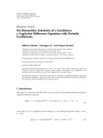
Báo cáo hóa học: " Research Article Implementation and Validation of a New Combined Model for Outdoor to Indoor Radio Coverage Predictions" pptx
Bạn đang xem bản rút gọn của tài liệu. Xem và tải ngay bản đầy đủ của tài liệu tại đây (10.81 MB, 9 trang )
Hindawi Publishing Corporation
EURASIP Journal on Wireless Communications and Networking
Volume 2010, Article ID 215352, 9 pages
doi:10.1155/2010/215352
Research Article
Implementation and Validation of a New Combined Model for
Outdoor to Indoor Radio Coverage Predictions
Guillaume de la Roche,
1
Paul Flipo,
2
Zhihua Lai,
3
Guillaume Villemaud,
2
Jie Zhang,
1
and Jean-Marie Gorce
2
1
CWiND, University of Bedfordshire, Park Square Campus, Luton LU1 3JU, UK
2
CITI Laboratory/INSA, University of Lyon, 69621 Villeurbanne, France
3
Ranplan Wireless Network Design Ltd, 1 Kensworth Gate, Luton LU6 3HS, UK
Correspondence should be addressed to Guillaume de la Roche,
Received 2 July 2010; Accepted 13 August 2010
Academic Editor: Nicolai Czink
Copyright © 2010 Guillaume de la Roche et al. This is an open access article distributed under the Creative Commons Attribution
License, which permits unrestricted use, distribution, and reproduction in any medium, provided the original work is properly
cited.
A new model used to compute the outdoor to indoor signal strength emitted from an outdoor base station is presented. This
model is based on the combination of 2 existing models: IRLA (Intelligent Ray Launching), a 3D Ray Optical model especially
optimized for outdoor predictions, and MR-FDPF (Multiresolution Frequency Domain ParFlow), a 2D Finite Differenc e model
initially implemented for indoor propagation. The combination of these models implies the conversion of the ray launching paths
on the border of the buildings, into virtual source flows that will be used as input for the indoor model. The performance of the
new combined model is evaluated via measurements at 2 frequencies (WiMAX and WiFi). This solution appears to be efficient for
radio network planning, in term of both accuracy and computational cost.
1. Introduction
Indoor networks planning is increasingly important; that is
why tools have been developed to help operators to optimize
their networks. For example, such tools are necessary to find
the best parameters like the positions of the emitters, the
optimal radiated power, and the best channels. Moreover,
the quality of such tools relies for an important part on the
quality of the propagation model.
1.1. Context. Recently, attention has been given to optimiz-
ing the indoor radio coverage by using specific indoor solu-
tions such as Femtocells [1]. Such femtocells are deployed
directly inside buildings, thus efficiently enhancing both
the indoor radio capacity and coverage. However it is also
important to notice that femtocell users, since the femtocells
share the same spectrum than the other outdoor cells,
can be highly interfered by the outdoor cells [2]. Hence
accurate outdoor to indoor propagation tools, that are able
to compute the in-building signal due to outdoor cells, are
currently highly demanded by mobile operators. The aim of
this paper is to propose a new combined propagation model,
which could be a good approah for this purpose.
1.2. Related Work. Some works related to outdoor to indoor
radio prorogation were proposed in the past in another con-
text than femtocells. However, in most of these approaches
it was not requested to have such a detailed knowledge
of the indoor signal, whereas, in our case, very detailed
coverage maps are necessary in order to study for example
performanceoffemtocellsindifferent typical scenarios.
In [3], the identification of the outdoor to indoor signal
through walls opening was studied. Then in [4] it is shown
that many factors have an influence on the received power
inside a building such as the predicted penetration loss versus
frequency for a windowed wall. Moreover, reflections on the
outdoor obstacles also have a great influence on the indoor
radio coverage; that is why a cluster approach was proposed
in [5]. Finally, three-dimensional radio propagation models
for outdoor to indoor have been proposed for urban wireless
network planning [6] and for Relay Network deployment [7].
2 EURASIP Journal on Wireless Communications and Networking
1.3. Contribution. In [ 8], we recently proposed a combi-
nation of two propagation models for outdoor to indoor
radio propagation predictions, as well as an initial evaluation
giving promising results. This paper, in addition to the
preliminary results presented in [8], has two major contri-
butions:
(i) the details about the implementation of the com-
bined model are given;
(ii) the validation of the model with two measurement
campaigns is presented.
The paper will be organized as follows: in Section 2 an
overview of the main approaches for deterministic radio
propagation will be presented, then in Section 3 the combi-
nation of two carefully chosen models will be proposed. In
Section 4, the 2 measurement campaigns will be described,
followed by an evaluation of the performance of the model
in Section 5. Finally, perspectives and conclusions will be
developed in Section 6.
2. Approaches for Deter ministic
Radio Propagation
As explained in the introduction, the context of the present
work is to compute environment-specific radio coverage
maps that take as accurately as possible into account the
geometries of the environment. Approaches for deterministic
simulation of radio waves can be divided into two main
families, depending on the theoretical laws on which they are
based on.
(i) RO models use Descartes laws, where the reflections
and diffra ctions of the signal on the obstacles are
computed by tracing all the possible paths between
the emitters and the receivers.
(ii) FD models use partial differential equations in order
to numerically solve the Maxwell’s equations on a
discrete grid.
In the following, properties related to these two families
of models will be investigated.
2.1. Ray-Optical-Bas ed Models. RO models, has been widely
used for predicting radio propagation [9, 10]. At each
receiving point, the signal level is computed as the sum of all
the rays (due to transmissions, reflections, and diffractions)
passing through this point. RO models are nowadays a com-
mon approach for deterministic radio coverage simulation,
hence they have been implemented in commercial software
such as [11, 12]. The two most common implementations
are Ray Tracing and Ray Launching where:
(i) ray Launching emits the rays from the transmitter.
Signal strength degenerates as the rays propagate and
additional loss is added when rays reflect or diffract
from walls;
(ii) ray Tracing traces the rays backwards, that is, it
searches all the possible paths arriving at each
receiving positions.
It is important to notice that the complexity of such models
can be very high in scenarios where the number of walls
is high, thus where numerous reflections/diffractions occur.
This is especially the case in 3D environments. That is why
most of the recent research has been focused on the reduction
of the complexity of RO models. Recently, a Ray Launching
model called IRLA [13] has been proposed in which the
following optimizations are used:
(i) a cube approach where the initial environment
is divided into cubes. In this approach the rays
between faces of cubes are computed, thus avoiding
to compute all the rays between all the points inside
the cubes [13];
(ii) an optimized approach for reducing the angular
dispersion which is often a concern in Ray Launching
when the distance from the emitter becomes large,
since the number of rays to be launched has to be
limited [14];
(iii) a parallel implementation where the computation of
the rays is distributed among processes thus reducing
a lot the simulation time [15].
IRLA is one component of the combined approach proposed
in this paper.
2.2. Finite-Difference-Bas ed Models. The most common
approach is the well known FDTD proposed in [16]which
numerically solves Maxwell’s equations and thus provides a
high accuracy. However, a disadvantage is that the size of the
pixels of the spatial grid has to be very small compared to
the wavelength of the signal, leading to a high complexity for
large scenarios. That is why, due to its high memory require-
ments, such FD models used to be applied only to antenna
design or electronic circuits. Nevertheless, since computers
become more and more powerful, researchers have started
to use such models for radio coverage predictions as well,
and more especially for indoor areas [17, 18]. Moreover,
and in order to reduce the complexity, another FD model
called ParFlow has been proposed [19]. In this approach,
restricted to 2D, the magnetic fields are approximated with
a unique scalar field thus reducing the number of variables
(there is only one field to take into consideration instead
of E and H fields). Recently, a similar approach called MR-
FDPF based on a transposition of the ParFlow equations in
the frequency domain has been proposed [20], in which the
following optimizations have been proposed:
(i) a multiresolution approach, in which most of the
complexity of the resolution of the equations is
gathered into a unique preprocessing. Therefore the
time duration for simulating each source becomes
very fast compared to usual FD models in the time
domain [20];
(ii) an calibration of the parameters of the model in order
to make it suitable for indoor simulation even if the
modelisrestrictedto2D[21];
(iii) an improvement of the model in order to perform
OFDM simulations which is out of scope of this
paper [22].
EURASIP Journal on Wireless Communications and Networking 3
MR-FDPF model is the second component of the combined
approach of this paper.
2.3. Comparison. RO models and FD models are very
different and both of them have advantages and drawbacks.
Comparisons between them have been developed in [23] the
main properties can been summarized as follows depending
on 3 criteria:
(i) complexity: For FD models, it depends mainly on
the size of the scenario, whereas for RO models it
depends mainly on the number of walls;
(ii) accuracy: FD is in general more accurate because
the number of reflections/diffract ions is not limited
unlike RO;
(iii) 3D extension: RO is in genera l less computational
demanding than FD; that is why 3D RO models are
commonly implemented in 3D whereas FD m odels
are usually in 2D in order to simulate large enough
scenarios.
3. Combination of 2 Models
3.1. Concept. Taking into consideration the properties
described in Section 2.3, it appears as an optimal choice
to select the most appropriate approach depending on the
location, that is:
(i) indoors: the scenario is not very large, and made
of numerous walls; that is why the number of
reflections/diffractions is very high. Moreover, in case
of multifloored buildings, the scenario at each floor
is quite flat, that is, a 2D approximation of the
propagation is a suitable assumption. Hence in this
case a 2D FD model such as MR-FDPF appears to be
the most favorable;
(ii) outdoors: the environment is not flat and cannot be
easily approximated with a 2D model, in particular in
scenarios with high buildings where antennas can be
located on the roofs. Furthermore, there is more open
space areas and the number of reflections to compute
is smaller than that indoors. Finally the size of the
scenario is too large to be computed with FD model.
Thatiswhyinthiscasea3DROmodelsuchasIRLA
is preferred.
Hence the new model for outdoor to indoor predictions
proposed in this paper combines IRLA (for the outdoor
propagation part) with MR-FDPF (for the in-building
propagation). It is to be noticed that, in the literature,
other combined RO/FD models such as [24–26]havebeen
proposed. However these models were restricted to indoors,
and a FD model was used only for the parts of the
scenario requiring more details. Thus, at the knowledge of
the authors, no combined RO/FD approach for outdoor to
indoor has been already proposed.
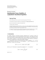
3.2. Implementation. The method is illustrated in Figure 1
and can be divided into the following steps:
Diffracted rays
Reflected rays
Direct
paths
E
Considered
floor level
Figure 1: Schematic representation of the combined approach. First
the outdoor part is simulated, then the incoming indoor flows are
computed and used for the indoor simulation.
3.2.1. Outdoor IRLA Prediction. The outdoor IRLA predic-
tion is performed. 3D rays are launched in all the directions
and recursively reflected and diffracted on the obstacles. The
tool is based on a maximum number of 15 reflections and 15
diffractions, which provides high accuracy. Since IRLA has
a cube approach, a resolution of 5 cm is chosen, that is, the
received signal power is computed every 5 centimeters. The
3D antenna pattern is generated from horizontal and vertical
2D antenna pattern obtained from the data sheets [15].
3.2.2. MR-FDPF Equivalent Sources Computations. In each
cube located on the borders of the building (at the height
corresponding to the floor), the amplitudes and directions
of all the N rays reaching the cube are stored. Each arriving
ray is represented by a vector v
i
and the equivalent ParFlow
source (flows are represented by c omplex numbers [20].) can
be computed from the vector V corresponding to all the
rays, that is, V
=
N−1
i=0
v
i
. In this case, the amplitude of the
equivalent source corresponds to the amplitude of V and the
phase of the equivalent source corresponds to the direction
of V.
3.2.3. Indoor MR-FDPF Prediction. The indoor radio cov-
erage is computed in 2D (a 5 cm resolution 2D cut of the
scenario at the height of the floor is taken) using the MR-
FDPF model and using the previously calculated equivalent
sources. It is to be noticed that, due to the properties of
MR-FDPF model, the complexity of simulating many sources
(i.e., all the borders of the building) is in the same oder than
for one source only.
3.3. Calibration. In the case when the parameters corre-
sponding to the materials are not perfectly well known
it may be u seful to calibrate the model. This is the
common approach used by all propagation tools and most
of commercial network planning software such as [11, 12].
Moreover, based on the fact that MR-FDPF is restricted to
4 EURASIP Journal on Wireless Communications and Networking
2D, it is important to compensate for this approximation
by properly adapting the parameters of the model based on
measurements as explained in [21]. In this paper, it was show
that, by modifying the attenuation of air, it was possible to fit
a3D free-space model with a 2D modeling.
Since the number of materials could be high it is not
possible to test all the possible values in a short time. That
is why meta heuristic methods have been implemented.
(i) Calibration of IRLA is based on Simulated Annealing
[27].
(ii) Calibration of MR-FDPF is calibrated using the
Direct Search algorithm [28].
The choice of a search method is due to the fact that IRLA
has few parameters to optimize (since the buildings are
represented by a single material) which can be solved in
a short time using Simulated Annealing. On the contrary
MR-FDPF models all the materials of the different walls
(for example, as we be detailed later, there are 8 parameters
to calibrate in this scenario, which cannot be optimized in
a short time using Simulated Annealing. Therefore Direct
Search is chosen providing a less accurate result but in a
shorter time. Let us remind that the model we propose in
this paper is aimed at wireless network planners, that is,
the calibration of the materials has to be performed in a
short time, and since all the elements of the scenario (such
as passing users, furnitures) are not simulated, reaching the
absolute global minimum is not of practical use.
The function to minimize during the calibration is the
RMSE defined as:
RMSE
=
1
N
N−1
i=0
(
M
i
− S
i
)
2
,
(1)
where: N is the number of comparison points, M
i
is the
measured received signal at location i,andS
i
is the simulated
received signal at location i.
Typically, calibration of IRLA takes few seconds (since
all the rays as stored in the memory it is not required to
run numerous simulations), whereas MR-FDPF is calibrated
in few minutes because multiple independent predictions
have to be run. Based on our experience, calibration is
important mostly outdoors where database information of
the environment is limited, and due to more frequent
unpredictable phenomenas such as moving vehicles and fast
fading.
4. Scenario and Measurements
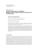
The scenario for the evaluation of the model is the INSA
university campus in Lyon, France (see Figure 2). The size
of the scenario is 800
× 560 meters. The size of CITI building
(surrounded in red in Figure 2), where the indoor radio
coverage is simulated, is approximately 110
× 100 meters. Its
height is 11 meters.
The combined models requires to work at two scales, that
is, an outdoor scale where a database of the buildings without
their content is used, and an indoor scale where the details of
E1
E2
Figure 2: Outdoor to indoor scenario. In red: the building where
the indoor measurements were performed. E1 and E2 represent the
position of each emitter and the black arrows show the directions
where the directive antennas were pointing.
the building to simulate are taken into consideration. Hence
two databases of the scenario were generated:
(i) The outdoor database, required by IRLA, was created
using google maps for extrac ting the shapes of the
buildings, and a laser meter to measure the height
of each building. Hence it is not a real full 3D
database but a 2.5D database, in a .dat format
similar to the one used by commercial RO software.
After calibration based on the approach detailed in
Section 3.3,itwasverifiedthatitwassuitableto
use the same unique material for all the buildings.
Hence there was three parameters to calibrate for
the ray launching, corresponding to the losses for
transmission, reflection and diffraction.
(ii) The indoor database containing all the walls of the
floors used by MR-FDPF was generated from the
.dx f format architect files. A 2D cut of the floor
in the horizontal plane was used. The environment
was modeled using one material corresponding to
air plus 3 other materials for the obstacles: concrete
for the main walls, plaster for the internal walls and
glass for the windows. In MR-FDPF there are two
parameters to define a material, that is, the refraction
index n and the electrical permittivit y on which the
attenuation coefficient α relies. That is why in this
case there was 8 parameters in total to calibrate.
To validate the model, two measurement campaigns at
different frequencies and emitters’ locations were performed
in the same scenario, as detailed in Table 1. The two frequen-
cies chosen for the validation (i.e., 3.5 GHz and 2.4 GHz)
correspond respectively to the frequencies of Worldwide
Interoperability for MicrowaveAccess (WiMAX) andWireless
Fidelity (WiFi) in Europe.
EURASIP Journal on Wireless Communications and Networking 5
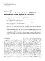
(a) ETS-Lindgren Antenna (b) Stella Doradus Antenna
Figure 3: Directive antennas used at the emitter.
Table 1: Measurement campaigns.
Experiment 1 Experiment 2
Frequency 3.5 GHz 2.4 GHz
Emitted power 0 dBm 0 dBm
Position on map E1 E2
Emitting antenna
ETS-Lindgren Stella Doradus
Horn antenna Parabolic antenna
Model 3115 Model 24 SD21
Gain 10dBi 20.5dBi
HPBW 38
◦
(V), 45
◦
(H) 15
◦
(V), 15
◦
(H)
Polarization Vertical Vertical
Table 2: Measurement equipment.
Emitter Agilent Digital RF Signal Generator
Receiver N9340A Handheld RF Sp ectrum Analyzer
The directive antennas (see Figure 3), located at approx-
imately 3 m hight, were pointing on CITI building in the
directions represented in Figure 2 (represented by arrows).
The equipment for the measurements is detailed in
Table 2. A total of 104 measurement points were chosen
(32 indoors and 72 outdoors). At the receiver’s side, omni-
directionnal antennas were used. Moreover, in order to avoid
fading effects, these antennas were slightly moved and the
mean value after continuous 20 second measurements was
recorded.
Before running the MR-FDPF simulations, IRLA has
been calibrated for both measurement campaigns, providing
a RMSE of 8 dB, which is acceptable considering the
arguments given in Section 3.3 and also the fact that the
points where distributed in the scenarios and some of them
far from the building of interest (see Figure 4(b) for the
location of these points).
Table 3: Accuracy of the model: RMSE/ME in dB.
X Experiment 1 Experiment 2
No calibration 2.80/0.301 2.28/ − 0.53
Calibration (4 points) 2.61/
− 0.22 1.77/ − 0.32
Calibration (all points) 2.39/0.09 1.17/0.21
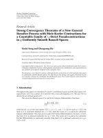
5. Results
As an illustration, the rays and the coverage map computed
with IRLA and corresponding to experiment 1 are plotted in
Figure 4.
The simulated sig nal inside the CITI building based on
the new combined model is plotted in Figure 5 (Exper-
iment 1) and Figure 6 (Experiment 2), as well as the
comparison between simulation and measurements for the
received signals (before calibration of MR-FDPF). It is seen
on these figures that the effects of the windows are well taken
into account, and that the measurements and simulation are
well in accordance. Moreover, and especially in Experiment 1
(due to the height of the buildings) the reflections of
the signal on neighboring buildings coming through the
windows is visible.
In order to evaluate the accuracy of the model more
in details, the RMSE values as well as the ME are plotted
in Table 3, depending on if MR-FDPF is calibrated, and
depending on the number of points used for the calibration.
It is verified that, even without calibration (default
material values for the indoor walls) the model perfor m s
well (less than 3 dB RMSE and less than 1 dB ME, which
corresponds to the accuracy that MR-FDPF reaches for
indoor simulations only [21]). Moreover, and as expected,
calibrating the model using few points (4) improves the
accuracy. As an illustration of what is the best possible
accuracy the model could reach, the RMSE after calibrating
using all the points is also given. However and as said bellow,
the aim of such model is to be used by radio engineers in
6 EURASIP Journal on Wireless Communications and Networking
(a) Outdoor Rays
−40
−150
(dBm)
(b) Outdoor coverage map
Figure 4: IRLA simulation (Experiment 1).
−70
−100
(dBm)
(a) Radio coverage map
0 5 10 15 20 25 30 35
75
80
85
90
95
100
Measurement ID
Received power (dBm)
Measurements
Simulations
(b) Comparison between measur ements and simulation
Figure 5: Outdoor to Indoor simulation results (Experiment 1).
order to save time due to radio measurement campaigns that
is why such calibration using all the points has no practical
meaning. Nevertheless it is proven in this experiment that
only few measurement points suffice to improve the model
and reach a high a ccuracy (Less than 2 dB in the case of
WiFi). Finally, let us just notice that in practice it makes no
sense to reach lower values of accuracy (typically less than
2 dB), since the accuracy of the measurement equipment
(even after the small scale fading is removed) may have larger
variations.
The time durations of the simulations are given in Table 4
and it is shown that the total simulation time (once the MR-
FDPF preprocessing has been already done) for one outdoor
to indoor prediction is less than two minutes on a standard
computer. The time durations we give are for the full radio
coverage, that is, for all points of the scenarios. Let us remind
here that the preprocessing of MR-FDPF does not need to
be run if the walls are not modified, since the ParFlow
scattering matrices does not depend on the location of the
sources.
EURASIP Journal on Wireless Communications and Networking 7
−60
−90
(dBm)
(a) Radio coverage map
0 5 10 15 20 25 30 35
65
70
75
80
85
90
95
Measurement ID
Received power (dBm)
Measurements
Simulations
(b) Comparison between measurements and simulation
Figure 6: Outdoor to Indoor simulation results (Experiment 2).
Table 4: Performance of the model: simulation times (on PC,
2.4 GHz, 2 GbRAM).
X IRLA MR-FDPF Total
Preprocessing 0s 41s 41s
Simulation 58 s 57 s 115 s
5.1. Advantages of the Model. It is important to notice that,
without combining MR-FDPF with IRLA, it would not have
been possible to compute the whole scenario with MR-
FDPF only, due to high memory requirements during the
preprocessing step. However, by supposing that this amount
of memory is large enough, it is then possible to interpolate
the simulation time duration it would take for simulating
the whole scenario with MR-FDPF. Indeed, and as detailed
in [ 20 ], the complexity of the propagation phase of MR-
FDPF varies in O(log
2
(N) · N
2
), where N is the smallest
dimension of the scenario in pixels. Thus a simulation of the
full environment (560 meter large) at the same resolution
would be l og
2
(560/100) · (560/100)
2
= 78 times slower,
that is, it would take approximately 2.5 hours instead of less
than 2 minutes (115s) with the proposed combined model.
Furthermore, such simulation would only simulate a 2D
cut, where the height of the outdoor emitters would not
be properly taken into account, hence it would provide a
low accuracy, compared to the approach we use where the
outdoor signal effects are simulated in 3D. Consequently, the
new model proposed in this paper is advantageous both in
term of speed and accuracy.
6. Conclusions and Perspectives
The solution provided in this paper has been shown to
efficiently compute the outdoor to indoor radio propagation
in one building due to the following reasons:
(i) it combines the advantages of a full 3D geometric
model for the outdoor part, and a n indoor accurate
FD model where 2D is sufficient due to the flatness of
the floors;
(ii) only the details of the considered buildings have
to be known, whereas the other buildings are only
represented by their shape and height;
(iii) it is a deterministic model, that is, the propagation
effects such as the losses through windows are well
taken into account, offering a RMSE between simula-
tion and measurements of less than 3 dB indoors for
a simulation time of less than 2 minutes;
(iv) is can be easily implemented on a standard PC
and does not require the use of expensive powerful
computers;
(v) the combined approach gives the opportunity to use
the MR-FDPF for large scenarios, which would have
not been possible based on MR-FDPF only.
This model, due to is performance will thus be used in a
network planning tool in particular to study the interference
produced by outdoor cells on indoor femtocells. However it
is to be noticed that this paper only provides information
about the expected mean power, which cannot be sufficient
to completely charac terize a complex radio link for modern
systems. Hence our future work include the two following
tasks:
(i) MR-FDPF provides us with an accurately discretized
map of the power, thus enabling to evaluate the
spatial behavior of the channel, which was presented
in [29] for indoor scenarios. However this needs to be
validated with measurements for outdoor to indoor
scenarios;
8 EURASIP Journal on Wireless Communications and Networking
(ii) ongoing work [22] gives us the possibility to per form
wideband simulations, leading to more information
such as Power Delay Profiles, delay spread, Doppler
spread. Thus new measurements have to be per-
formed in order to verify if such features are also true
in outdoor to indoor scenarios using the combined
model.
Acronyms
FDTD: Finite Difference Time Domain,
FD: Finite Difference,
IRLA: Intelligent Ray Launching,
ME: Mean Error,
MR-FDPF: Multi Resolution Frequency Domain ParFlow,
OFDM: Orthogonal Frequency Division Multiplexing,
RMSE: Root Mean Square Error,
RO: Ray Optical,
WiFi: Wireless Fidelity,
WiMAX: Worldwide Interoperability for
MicrowaveAccess.
Acknowledgments
This paper is supported by 2 European FP7 funded research
projects: “CWNETPLAN” on Combined Indoor and Out-
door ra dio propagation and “IPLAN” on indoor wireless
network planning. The authors would like to thank Malcolm
Foster for his useful comments and suggestions.
References
[1] J. Zhang and G. de la Roche, Femtocells: Technologies and
Deployme nt , John Wiley & Sons, New York, NY, USA, 2010.
[2] D. L
´
opez-P
´
erez, A. Valcarce, G. de la Roche, and J. Zhang,
“OFDMA femtocells: a roadmap on interference avoidance,”
IEEE Communications Magazine, vol. 47, no. 9, pp. 41–48,
2009.
[3] Y. Miura, Y. Oda, and T. Taga, “Outdoor-to-indoor prop-
agation modelling with the identification of path passing
through wall openings,” in Proceedings of the 13th IEEE
International Symposium on Personal, Indoor and Mobile Radio
Communications (PIMRC ’02), vol. 1, September 2002.
[4] S. Stavrou and S. Saunders, “Factors influencing outdoor
to indoor radiowave propagation,” in Proceedings of the
12th International Conference on Antennas and Propagation
(ICAP ’03), vol. 2, April 2003.
[5] S. Wyne, N. Czink, J. Karedal, P. Almers, F. Tufvesson, and A. F.
Molisch, “A cluster-based analysis of outdoor-to-indoor office
MIMO measurements at 5.2 GHz,” in Proceedings of the 64th
IEEE Vehicular Technology Conference (VTC ’06), pp. 22–26,
September 2006.
[6] T. K
¨
urner and A. Meier, “Prediction of outdoor and outdoor-
to-indoor coverage in urban areas at 1.8 Ghz,” IEEE Journal on
Selected Areas in Communications, vol. 20, no. 3, pp. 496–506,
2002.
[7] S. Reynaud, M. Mouhamadou, K. Fakih et al., “Outdoor to
indoor channel characterization by simulations and measur-
ments for optimising WiMAX relay network deployment,” in
Proceedings of the 69th IEEE Vehicular Technology Conference
(VTC ’09), April 2009.
[8]G.delaRoche,P.Flipo,Z.Lai,G.Villemaud,J.Zhang,
and J M. Gorce, “Combination of geometric and finite
difference models for radio wave propagation in outdoor to
indoor scenarios,” in Proceedings of the European Conference
on Antennas and Propagation (EuCAP ’10), Barcelona, Spain,
April 2010.
[9] V. Degli-Esposti, F. Fuschini, E. M. Vitucci, and G. Falciasecca,
“Speed-up techniques for ray tracing field prediction models,”
IEEE Transactions on Antennas and Propagation, vol. 57, no. 5,
pp. 1469–1480, 2009.
[10] D.N.Schettino,F.J.S.Moreira,andC.G.Rego,“Efficient ray
tracing for radio channel characterization of urban scenarios,”
IEEE Transactions on Magnetics, vol. 43, no. 4, pp. 1305–1308,
2007.
[11] Y. Corre and Y. Lostanlen, “3D urban propagation model for
large ray-tracing computation,” in Proceedings of the Inter-
national Conference on Electromagnetics in Advanced Appli-
cations (ICEAA ’07), pp. 399–402, Torino, Italy, September
2007.
[12] G. Woelfle, B. E. Gschwendtner, and F. M. Landstorfer,
“Intelligent ray tracing—a new approach for field strength
prediction in microcells,” in Proceedings of the 47th IEEE
Vehicular Technology Conference (VTC ’97), vol. 2, pp. 790–
794, 1997.
[13] Z. Lai, N. Bessis, G. DelaRoche, H. Song, J. Zhang, and
G. Clapworthy, “An intelligent ray launching for urban
prediction,” in Proceedings of the 3rd European Conference
on Antennas and Propagation (EuCAP ’09), pp. 2867–2871,
Berlin, Germany, March 2009.
[14] Z. Lai, N. Bessis, G. de la Roche, P. Kuonen, J. Zhang, and
G. Clapworthy, “A new approach to solve angular dispersion
of discrete ray launching for urban scenarios,” in Proceedings
of the Loughborough Antennas and Propagation Conference
(LAPC ’09), pp. 133–136, Loughborough, UK, November
2009.
[15] Z. Lai, N. Bessis, P. Kuonen, G. de la Roche, J. Zhang, and
G. Clapworthy, “On the use of an intelligent ray launching
for indoor scenarios,” in Proceedings of the 4th European Con-
ference on Antennas and Propagation (EuCAP ’10), Barcelona,
Spain, April 2010.
[16] K. Yee, “Numerical solution of initial boundary value prob-
lems involving Maxwell’s equations in isotropic media,” IEEE
Transactions on Antennas and Propagation, vol. 14, no. 13, pp.
302–307, 1966.
[17] G. Kondylis, F. DeFlaviis, G. J. Pottie, and Y. Rahmat-Samii,
“Indoor channel characterization for wireless communica-
tions using reduced finite difference time domain,” in Proceed-
ings of IEEE Vehicular Technology Conference (VTC ’99), vol. 3,
pp. 1402–1406, May 1999.
[18] A. Lauer, I. Wolff, A. Bahr, J. Pamp, J. Kunisch, and I.
Wol ff, “Multi-mode FDTD simulations of indoor propagation
including antenna properties,” in Proceedings of the 45th
IEEE Vehicular Technology Conference (VTC ’95), pp. 454–458,
Chicago, Ill, USA, July 1995.
[19] M. Pahud, F. Guidec, and T. Cornu, “Performance evaluation
of a radiowave propagation parallel simulator,” in Proceedings
of the 3rd International Conference on Massively Parallel
Computing System, April 1998.
[20]J M.Gorce,K.Jaffr
`
es-Runser, and G. de la Roche, “Deter-
ministic approach for fast simulations of indoor radio wave
propagation,” IEEE Transactions on Antennas and Propagation,
vol. 55, no. 3, pp. 938–948, 2007.
EURASIP Journal on Wireless Communications and Networking 9
[21] G. de la Roche, K. Ja ffr
`
es-Runser, and J M. Gorce, “On
predicting in-building WiFi coverage with a fast discrete
approach,” International Journal of Mobile Network Design and
Innovation, vol. 2, no. 1, pp. 3–12, 2007.
[22] J M. Gorce, G. Villemaud, and P. Flipo, “On simulating
propagation for OFDM/MIMO systems with the MRFDPF
model,” in Proceedings of the 4th European Conference on
Antennas and Propagation (EuCAP ’10), Barcelona, Spain,
April 2010.
[23] L. Nagy, R. Dady, and A. Farkasvolgy i, “Algorithmic complex-
ity of FDTD and ray tracing method for indoor propagation
modelling,” in Proceedings of the 3rd European Conference On
Antennas and Propagation, Berlin, Germ any, March 2009.
[24] Y. Wang, S. Safavi-Naeini, and S. K. Chaudhuri, “A hybrid
technique based on combining ray tra cing and FDTD methods
for site-specific modeling of indoor radio wave propagation,”
IEEE Transactions on Antennas and Propagation, vol. 48, no. 5,
pp. 743–754, 2000.
[25] S. Reynaud, C. Guiffaut, A. Reineix, and R. Vauzelle, “Model-
ing indoor propagation using an indirect hybrid method com-
bining the UTD and the FDTD methods,” in Proceedings of the
7th European Conference on Wireless Technology (ECWT ’04),
pp. 345–348, Amsterdam, The Netherlands, October 2004.
[26] M. Thiel and K. Sarabandi, “3D-wave propagation analysis
of indoor wireless channels utilizing hybrid methods,” IEEE
Transactions on Antennas and Propagation,vol.57,no.5,pp.
1539–1546, 2009.
[27] V. Granville, M. Krivanek, and J P. R asson, “Simulated
annealing: a proof of convergence,” IEEE Transactions on
Pattern Analysis and Machine Intelligence, vol. 16, no. 6, pp.
652–656, 1994.
[28] D. R. Jones, C. D. Perttunen, and B. E. Stuckman, “Lipschitzian
optimization without the Lipschitz constant,” Journal of
Optimization Theory and Applications, vol. 79, no. 1, pp. 157–
181, 1993.
[29] G. de la Roche, X. Gallon, J M. Gorce, and G. Villemaud,
“On predicting fast fading strength from Indoor 802.11
simulations,” in Proceedings of the International Conference on
Electromagnetics in Advanced Applications (ICEAA ’07),pp.
407–410, Torino, Italy, September 2007.