Báo cáo hóa học: " Research Article Combined Distributed Turbo Coding and Space Frequency Block Coding Techniques" pptx
Bạn đang xem bản rút gọn của tài liệu. Xem và tải ngay bản đầy đủ của tài liệu tại đây (1.05 MB, 14 trang )
Hindawi Publishing Corporation
EURASIP Journal on Wireless Communications and Networking
Volume 2010, Article ID 327041, 14 pages
doi:10.1155/2010/327041
Research Article
Combined Distributed Turbo Coding and Space Frequency
Block Coding Techniques
V. Bota,
1
Zs. A. Polgar,
1
A. Silva,
2
S. Te odoro,
2
M. P. Stef,
1
A. Moc¸o,
2
A. Botos,
1
and A. Gameiro
2
1
Communications Department, Technical University of Cluj Napoca, 400027 Cluj Napoca, Romania
2
Institute of Telecommunications, University of Aveiro, 3800-193 Aveiro, Portugal
Correspondence should be addressed to V. Bota,
Received 30 March 2010; Revised 26 July 2010; Accepted 7 November 2010
Academic Editor: Mohamed Hossam Ahmed
Copyright © 2010 V. Bota et al. This is an open access article distributed under the Creative Commons Attribution License, which
permits unrestricted use, distribution, and reproduction in any medium, provided the original work is properly cited.
The distributed space-time (frequency) coding and distributed channel turbo coding used independently represent two
cooperative techniques that can provide increased throughput and spectral efficiency at an imposed maximum Bit Error Rate
(BER) and delay required from the new generation of cellular networks. This paper proposes two cooperative algorithms that
employ jointly the two types of techniques, analyzes their BER and spectral efficiency performances versus the qualities of the
channels involved, and presents some conclusions regarding the adaptive employment of these algorithms.
1. Introduction
Most of the services that should be provided by future
wireless networks require low or very low BER and delay
values and high data rates. The cooperative transmission
techniques represent one of the most promising solutions
in wireless networks for provisioning the increased capacity,
extended coverage, and improved fairness [1–3]required
by such services. They could ensure low BER, while still
inserting limited transmission delays, and also significantly
improve the spectral efficiency of wireless systems.
Another technique that could fulfill the above require-
ments is the Multiple Input Multiple Output-Orthogonal
Frequency Division Multiplexing (MIMO-OFDM) [4, 5],
which has already been adopted in high rate wireless commu-
nications standards, such as WiMAX and LTE. However, con-
sidering a conventional cellular architecture with colocated
antennas, there is significant correlation between channels in
some environments; moreover, the use of an antenna array
at the user terminals (UTs) may not be feasible due to size,
cost, and hardware limitations. The OFDM-MIMO could be
also implemented through cooperation of users, which share
their antennas and thereby create a Virtual Antenna Array
(VAA) or a Virtual MIMO (VMIMO) system. In this context,
the concept of Distributed Space-Time Coding (DSTC) was
introduced in [6, 7]. This approach allows single-antenna
devices to gain some benefits from spatial diversity without
the need for physical antenna arrays. Several recent works [8,
9] have considered either the design of DSTC or Distributed
Space-Frequency Coding (DSFC) or the application of the
existing space-time/frequency codes in a distributed manner
for the wireless relay-based systems. The use of Space-
Time Block Coding (STBC) based on Alamouti schemes
[10] implemented in a distributed manner in OFDM-based
cooperative schemes has been discussed in [11, 12], while a
full-rate and full-diversity quasiorthogonal STBC scheme to
be applied in virtual antenna arrays was proposed in [13]. In
[14], Distributed Space-Frequency Block Coding (DSFBC)
schemes for OFDM-based cellular systems which use an
antenna array at the BS and a single antenna at both the UT
and RN have been proposed.
Another cooperative approach that aims at exploiting
diversity is the Distributed Forward Error Correction Coding
(DFEC). Such a cooperation scheme, proposed in [15],
was intended initially to create transmit diversity in the
uplink of a wireless system. Using standard FEC, parti-
tioning of code words and transmitting these parts by
the cooperating partners, together with error detection at
each partner, could overcome the drawbacks of a simple
cooperation based on repetition coding. The performances
of FEC-based cooperation schemes were investigated under
various channel conditions and power allocation modes
2 EURASIP Journal on Wireless Communications and Networking
in [16, 17], while some algorithms are provided in [18]
and throughput maximization methods are provided in
[19]. Niu and Lu [20] have combined the OFDM flexible
subcarrier allocation with distributed coding, extending
the cooperative communication strategy from the time
domain to the time-frequency domain, by incorporating the
Orthogonal Frequency-Division Multiple Access (OFDMA)
concept. Practical distributed coding protocols that use Rate-
Compatible Punctured Convolutional Codes (RCPCC) were
proposed and investigated in [21]. This approach ensures
high performances both for Amplify & Forward (AF) and
Decode & Forward (DF) relaying schemes, while maintaining
a low complexity.
One step further is the joint use of cooperative tech-
niques, such as DST(F)BC or DFEC, with Network Coding
(NC), which combines the advantages provided by each of
the involved techniques and diminishes their shortcomings.
Recent papers, such as [22–25], propose various versions of
combining these techniques which provide results that are
more than promising. Nevertheless, the employment of NC-
based techniques involves more elaborate cluster-selection
techniques which seem to be difficult to implement in the
present mobile cellular systems.
Therefore, this paper proposes two cooperation algo-
rithms, serving one UT, that employ in a joint manner
the distributed space frequency coding and distributed
FEC, analyzes their performances and compares these per-
formances with those of DSFC and DFEC cooperation
algorithms used independently. The paper is structured as
follows: Section 2 explains briefly the motivation of this
study, while Section 3 presents the cooperation protocol
and topologies used and briefly arguments their selection.
Section 4 describes the DSFC and DFEC cooperative algo-
rithms and the proposed combined DSFC+DFEC coop-
eration algorithms, while Section 5 briefly discusses the
evaluation of their spectral efficiency. Section 6 describes
the performance metrics employed and the test scenarios
used for performance evaluation; it presents the simula-
tion results obtained and analyzes these results. Finally,
Section 7 presents some conclusions regarding the selec-
tion of the cooperative algorithm according to the given
topology, scenario, and type of service that has to be
provided.
2. Motivation and Objectives
The performances of the cooperative algorithms, BER,
Bloc Error Rate (BLER), and spectral efficiency, are
strongly affected by the combining method of the signals
received on the source—destination and on the relay
(relays)—destination links. Two main categories of message-
combining methods could be used:
(i) symbol-level combining, which is specific to space-
time/space-frequency coding and to maximum ratio
combining. These message combining techniques
provide diversity gain,
(ii) bit-level combining, that is, bit-LLRs addition and/or
concatenation, which is characteristic to distributed
FEC. These message combining techniques provide
less diversity gain, but they provide coding gain.
These combining methods exhibit different degrees of
flexibility, when employed in different cooperative transmis-
sion scenarios. Symbol-level combining requires the same
constellation on each transmission link, regardless of the
significantly different qualities of the channels employed by
each cooperation phase. Bit-level combining has a greater
flexibility, allowing the use of different constellations on
different transmission links, according to each channel
state, fact that has significant impact upon the spectral
efficiency.
The joint use of the two types of message combining
could ensure both improved BER and flexibility, thus
providing greater spectral efficiency. One way to achieve
this mix of message combining in cooperative networks
would be to employ in a joint manner distributed FEC and
distributed diversity techniques, thus providing both coding
and diversity gains.
The main objective of the paper is to analyze the
performances of some particular cooperation algorithms
combining DSFC and DFEC within a topology containing
a virtual MIMO scheme that uses the antennae of one or two
relay nodes (RNs), to compare their BER and spectral effi-
ciency performances to those of cooperation schemes using
independently either the DSFC or DFEC techniques, and to
identify scenarios within which these combined distributed
coding schemes provide greater spectral efficiencies at an
imposed BER. The applicability of these algorithms to several
types of services, according to the BER and spectral efficiency
requirements, will also be briefly considered.
3. Cooperation Protocol and Topologies
This paper considers a test topology, with single-antenna
equipments, where two dedicated relay nodes (RN
1
,RN
2
),
fixed or nomadic, assist the communication between the Base
Station (BS) and the UT. The access scheme is OFDMA,
the constellations used are QPSK, 16, and 64 QAM and all
point-to-point transmissions are Single Input Single Output
(SISO) ones.
The cooperative algorithms studied employ the classical
two-phase cooperation protocol, which are supposed to
occur successively in time, but might not use the same signal
constellation.
(1) In the “broadcast phase”, the source node (BS or UT)
sends its message to the RN and to the destination
node (UT or BS, resp.). The content of the broadcast
message is specific to the cooperation algorithm
employed.
(2) In the “relaying phase”, the RNs decode the received
message, perform the processing specific to the coop-
eration algorithm employed and send their messages
to destination (UT or BS).
The destination jointly decodes the information received
from the RNs or both from the source and RNs, according to
the cooperation algorithm.
EURASIP Journal on Wireless Communications and Networking 3
Information bits N
i
and check bits N
c
Information bits N
i
and/or
additional check bits N
a
Information bits N
i
and/or
additional check bits N
a
Information bits N
i
and/or
additional check bits N
a
Broadcast-phase I DSTC or DSFC-phase II
RN
1
BS
RN
2
UT
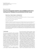
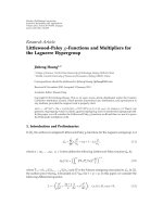
Figure 1: Topologies for DSFC-based cooperation algorithms: with two RNs (solid line); with one RN (dashed line).
The two phases of the cooperation protocol applied to
this topology are illustrated in Figure 1 for the downlink
(DL) connection; that is, the broadcast message is trans-
mitted to the RNs and UT, while the relay message, which
depends on the DFEC algorithm employed, is transmitted
jointly by the two RNs using a cooperative diversity scheme,
like DSTC or DSFC. The message sent during the broadcast
phase might be employed or not by the destination’s receiver.
Since the number of RNs is limited by relay assignment,
resource allocation and signaling issues, the test topology can
be simplified by imposing the source to act as one of the RNs
and transmit both during the broadcast phase, as source, and
during the relaying phase, as one of the RNs, as shown in
Figure 1.
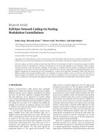
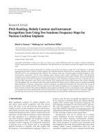
The asymmetrical two-RN topology, with different E
b
/N
0
ratios received from the two RNs, could be transformed into
a symmetrical topology for easier analysis and simulation,
by considering an equivalent E
b
/N
0
value that is received
from each RN on the RN-destination links, as shown in
Figure 2.
4. Cooperative Distributed Co ding Algorithms
This section gives a short overview of the cooperation
algorithms employing Alamouti-based DSFC and Turbo
Coding (TC)-based DFEC techniques and describes the
proposed combined DSFC-DFEC cooperation algorithms.
4.1. Distributed Space-Frequency Coding (DSFC). The topol-
ogy with two RNs contains five links; namely, the direct
BS-UT link, defined by the h
bu
channel, the BS-RN
i
links
(i
= 1, 2), defined by the h
br
i
(i = 1, 2) channels, and the
RN
i
-UT links, defined by channels h
r
i
u
(i = 1, 2), as shown
in Figure 1. Within the topology with one RN, the BS-RN
2
link is an ideal one, while the RN
2
-UT link is represented by
another realization of the h
bu
channel.
The operations performed by this DSFC algorithm
during cooperation are briefly described below.
(1) In the broadcast phase, the source node transmits the
coded block (N
i
information bits and N
c
check bits)
towards the RNs and destination, using a modulation
adapted to the channels involved.
(2) In the relaying phase, the RNs decode and re-
encode the message with the same FEC code, apply a
DSFC-Alamouti scheme [10] and transmit their per-
fectly synchronized messages on the RN
i
-destination
channels using the same signal constellation (not
necessarily the same as in the first phase).
(3) At the destination end, the DSFC-decoded symbols
and the ones received from the source during the
broadcast phase are MRC-combined to provide the
symbols that are fed to the FEC decoder. Because
this algorithm uses at destination signals received
both from RNs and the source, it will be denoted as
the composed DSFC, c-DSFC. Since the messages
received during the cooperation phases are combined
at QAM-symbol level, all links should use the same
modulation.
4 EURASIP Journal on Wireless Communications and Networking
RN
1
E
b1
/N
0
E
b2
/N
0
UT
RN
1
RN
2
E
bg
/N
0
= (E
b1
/N
0
+ E
b2
/N
0
)
E
b
/N
0
= (E
b1
/N
0
+ E
b2
/N
0
)/2
RN
2
UT
E
b
/N
0
E
bg
/N
0
E
b
/N
0
Figure 2: Nonsymmetrical (left) and symmetrical (right) DSFC topologies with two RNs.
To point out the effects of the direct link transmission
upon the performance of the DSFC scheme, an alternative
version, called simple DSFC (s-DSFC), which does not use
the direct link at the receiver’s end, is also considered. Hence,
different signal constellations might be used during the two
cooperation phases.
In the subsequent sections, we consider that all channels
involved are complex flat Rayleigh-faded channels, and the
noise samples have zero-mean and variance equaling σ
2
u
.
We also consider that the OFDM subcarrier separation is
significantly lower than the channel’s coherence bandwidth,
and so, the fading over two adjacent subcarriers can be
considered flat.
Considering the c-DSFC algorithm, the instantaneous
SNR on subcarrier p obtained after the MRC-combining
performed at destination between the symbols received on
the direct link and those provided by the Alamouti decoding
of the DSFC signals on the RN
i
-destination links is [14, 26]
SNR
p
=
(
1/2
)
h
p
r
1
u
2
+
h
p
r
2
u
2
+
h
p
bu
(
b
)
2
σ
2
u
,
(1)
where h
p
bu
(b) represents the complex coefficient of the flat
Rayleigh faded BS-UT channel, during the broadcast phase,
for the pth subcarrier with an average power E
{|h
p
bu
(b)|
2
}=
δ
2
ub
(b), h
p
r
i
,u
denotes the RN
i
-UT channel during relaying
phase, for the pth subcarrier with an average power of
E
{|h
p
r
i
u
|
2
}=δ
2
r
i
,u
, in the assumption that the fading over
two adjacent subcarriers can be considered flat; that is, h
p
r
i
u
is equal to h
p+1
r
i
,u
. We also assume that the noise variance of
the signals received at the UT during the two phases to be
equal, that is, σ
2
u
(b) = σ
2
u
(r) = σ
2
u
.
If the topology with one RN is considered, see Figure 1,
then the BS acts as the second RN (in the DL), and
therefore, in relation (1), h
p
r
2
u
should be replaced by h
p
bu
(r),
the complex flat Rayleigh BS-UT channel’s realization for the
pth subcarrier during the relaying phase.
If the direct link is not used in the decoding process at
the receiving end (the s-DSFC algorithm) the instantaneous
SNR on subcarrier p is expressed in a similar manner by (2)
[14, 26] and is smaller that the one ensured by the c-DSFC
algorithm, see(1)
SNR
p
=
(
1/2
)
h
p
r
1
u
2
+
h
p
r
2
u
2
σ
2
u
. (2)
If the channels are correctly equalized, we may assume
that the LLRs of all bits of the FEC codeword are extracted
from the same equivalent channel, with SNRs expressed by
(1) for the algorithm which employ the source-destination
link, respectively, by (2) for topologies which do not employ
this link.
4.2. Distr i buted FEC Cooperation Algorithms. Distributed
FEC algorithms use the classical two-phase cooperation
protocol [16, 17], applied within a topology with one RN,
for example, RN
1
, which is particularized in Figure 3.Most
of distributed FEC algorithms use the same encoder both
at source and at RN, some of them employing different
puncturing patterns for the two transmissions. Usually, Con-
volutional Turbo Codes (CTCs) or Low Density Parity Check
(LDPC) codes are employed to implement the distributed
FEC.
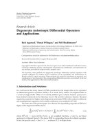
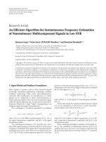
4.2.1. Distributed FEC with Incremental Redundancy. The
Incremental Redundancy DFEC (IR-DFEC) algorithm that
uses CTCs is briefly described below and represented in
Figure 3.
(i) Broadcast Phase. The UT (or the BS) encodes the N
i
information bits using a CTC code with a coding rate R
m
(the
mother code rate). The resulted check bits are appropriately
punctured according to a rate matching algorithm [27], to
obtain a desired coding rate R
c
. The resulted coded blocks of
length N
i
+ N
c
= N
i
/R
c
are then sent by the source (UT or
BS) over the source-destination and source-RN links.
(ii) Relaying Phase. The RN decodes the received block,
using a turbo decoder, and it re-encodes these bits using the
same CTC encoder. Then, it selects a number of additional
check bits N
a
= N
i
(1/R
a
− 1), by using a different puncturing
EURASIP Journal on Wireless Communications and Networking 5
pattern corresponding to a coding rate R
a
, and these bits are
transmitted over the RN-destination link. The two coding
rates R
a
and R
c
are chosen so that the global coding rate, R
g
,
which is expressed by (3), would equal the rate of the mother
code
R
g
=
N
i
N
i
+ N
c
+ N
a
=
R
a
· R
c
R
a
+ R
c
− R
a
· R
c
= R
m
. (3)
(iii) Decoding. At destination, before turbodecoding, the
blocks received both from source and RN are assembled and
completed according to the employed puncturing rules. The
N
i
information and the N
c
check bits generated by the source
are received at smaller equivalent SNR values, SNR
p
d
, than the
N
a
check bits generated by the relay, SNR
p
r
, as shown by (4),
fact that represents the main disadvantage of IR-DFEC
SNR
p
d
=
h
p
bu
(
b
)
2
σ
2
u
<
h
p
r
1
,u
2
σ
2
u
= SNR
p
r
. (4)
The advantage of the IR-DFEC scheme consists of the
relatively small amount of time-frequency resources required
by the relaying phase, which increase the spectral efficiency,
and the possibility to build distributed Hybrid Automatic
Repeat Request (H-ARQ) schemes based on this cooperation
scheme.
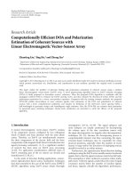
4.2.2. Hybrid Distributed FEC with Incremental Redundancy.
The effects of small SNRs on the direct link might be over-
come by a Hybrid IR-DFEC (HIR-DFEC) algorithm based
both on repetition and incremental redundancy encoding.
The HIR-DFEC algorithm is similar to the IR-DFEC one, see
Figure 3, but in the relaying phase the RN sends, besides the
N
a
check bits, the decoded information bits N
i
. The coding
rate obtained in the relaying phase is R
a
= N
i
/(N
i
+ N
a
).
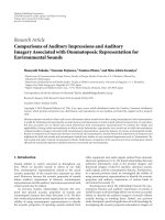
The decoding performed at the destination node is
schematically represented in Figure 4. The destination node
combines the LLRs corresponding to the information bits
received over the direct and relay links, then it reorders the
check bits received on the two links and concatenates them
in order to restore the LLR-flow of the complete R
g
-rate
codeword, which is fed into the turbo decoder.
The global coding rate R
g
is the same as the one of
the IR-DFEC algorithm, (3), but this algorithm involves
the transmission of two sets of N
i
information bits, and
therefore, in the computation of the payload bit rate and
spectral efficiency, a transmission rate, R
t
,givenby(5)
should be considered
R
t
=
N
i
2 · N
i
+ N
c
+ N
a
=
R
c
· R
a
R
c
+ R
a
. (5)
The spectral efficiency of this algorithm is smaller, but
the N
i
information bits are better protected, since they are
transmitted both on the direct and on the relay links, and
therefore, they are received under an equivalent SNR, SNR
p
,
expressed by (6), which is greater than the one ensured by
the IR-DFEC for these bits. As for the N
c
and N
a
check bits,
they are received on similar conditions as in the IR-DFEC
algorithm
SNR
p
=
h
p
r
1
,u
2
+
h
p
bu
(
b
)
2
σ
2
u
>
h
p
bu
(
b
)
2
σ
2
u
= SNR
p
d
. (6)
4.2.3. Combined DSFC+DFEC Cooperation Algorithms. Dis-
tributed turbo coding algorithms (IR-DFEC or HIR-DFEC)
are able to provide increased spectral efficiency, system
flexibility but also significant coding gains if the source-
RN and RN-destination links have good qualities. These
conditions cannot be ensured only by positioning the relay,
while the employment of powerful channel codes decreases
the spectral efficiency and increases the complexity.
The quality of the transmission between the RN and
destination can be significantly improved by using one or
two RNs to implement a DSFC (or DSTC) algorithm, due to
the diversity provided on the uncorrelated RN
i
-destination
links. In the same time, a small BER could be ensured in
the broadcast phase by placing the RNs closer to the source.
Therefore, the combined use of DFEC and DSFC algorithms
could provide improved performances and allow the use of
simplified relay selection algorithms.
The combined s-DSFC+DFEC algorithms proposed are
schematically represented in Figure 1 for the DL connection
in the particular case when only 2 relays are used to imple-
ment the s-DSFC in the relaying phase. A brief description of
the operations performed is presented below.
(i) Broadcast phase. The source (BS) broadcasts the N
i
information bits encoded with a CTC of rate R
c
(N
c
check bits) over the BS-UT and BS-RN
i
links.
(ii) Relaying phase. The RNs performs the DFEC decod-
ing, followed by the HIR-DFEC or IR-DFEC encod-
ing. Then, the two RNs perform the DSFC encoding,
that is, Alamouti scheme, described in Section 4.1,
using the same QAM constellation, which might be
different from the one employed during the broadcast
phase.
(iii) Decoding at destination. The destination performs the
following operations:
(1) demodulates and extracts the LLRs of the N
i
+
N
c
bits transmitted during the broadcast phase,
(2) extracts the symbols transmitted during relay
phase by SFC-decoding and extracts the LLRs of
the N
i
+N
a
(for HIR-DFEC) or N
a
(for IR-FEC)
received bits; note that the message received on
the direct link, during the broadcast phase, is
not used in this operation,
(3) combines the LLRs of the N
i
bits received on
both broadcast and relay phase (only for HIR-
DFEC),
(4) reorders the LLRs of the received bits and
performs the DFEC decoding.
6 EURASIP Journal on Wireless Communications and Networking
Base station/
user terminal
Data
source
Tur bo
encoder
Puncture I
UT/BS -RN
channel
Relay node
Tur bo
decoder
Tur bo
encoder
Puncture II
Info.bits N
i
Check bits N
c
BS-UT/UT-BS
channel
RN-UT/BS
channel
Check bits N
a
Unpuncture I
(check bits)
Unpuncture II
(check bits)
Bit ordering
Tur bo
decoder
User teminal/base station
Figure 3: Block diagram of IR-DFEC algorithm that employs CTCs.
Unpuncture I
Unpuncture II
Info. bits N
i
Info. bits N
i
Check bits N
c
BS-UT/UT-BS
channel
RN-UT/BS
channel
Check bits N
a
User teminal/base station
LLR sumation
bit ordering
Tur bo
decoder
Figure 4: Hybrid-distributed turbo coding. Processing performed at destination.
4.3. Some Considerations Regarding the Effects of the Errors
on the Source-Relays Links. The qualities of the source-
relay links have a significant effect upon the global BER
provided by the cooperative algorithms. In order to evaluate
their effects upon the BER performance of the proposed
algorithms, we assume that if the block received by the
one of the RNs is decoded with errors, the RN re-encodes
the decoded bits and apply the corresponding cooperation
algorithm. Another option would be to make the RN
stop transmitting any message and to signalize this fact
to destination. But this second approach would require
additional signaling and adaptive use of the cooperation
algorithm at destination.
Denoting by PER
x
the block error probability at destina-
tion provided by the algorithm x, if the messages transmitted
by RNs are correct, and by PER
S−R1
and PER
S−R2
the block
error probabilities after the RN
i
decoding, the global block
error probability of the whole cooperative algorithm, PER
gx
,
can be expressed using the probability of a correct decoding
at destination P
cgx
,by
P
cgx
=
(
1
− PER
x
)
·
(
1
− PER
S−R1
)
·
(
1
− PER
S−R2
)
≈
(
1
− PER
x
)
·
(
1
− PER
S−R1
− PER
S−R2
)
=⇒
PER
gx
= PER
x
+PER
S−R1
+PER
S−R2
− PER
x
·
(
PER
S−R1
+PER
S−R2
)
.
(7)
ThevaluesofPER
S−R1,2
and BER
S−R1,2
differ for the
two ways of transmission. For the DL connection, due to
the higher BS antenna and to the possibility to employ
RNs that have Line Of Sight (LOS) channels to the BS,
the two PER
S−Ri
, and the corresponding BER
S−Ri
, can be
considered negligible and the global PER is established by
EURASIP Journal on Wireless Communications and Networking 7
the PER
x
provided by the cooperative algorithm x at the
UT. For the UL connection, the error probabilities of the
UT-RN
i
links cannot be neglected and the global PER
gx
and BER
gx
are dictated by both the cooperative decoding in
the BS (destination), that is, PER
gx
and BER
x
, and by the
error probabilities of the UT-RN
i
links, that is, PER
S−Ri
and
BER
S−Ri
. Therefore, the BER
gx
and PER
gx
are expected to
be greater on the UL than on the DL connection, in such a
topology.
5. Computation of the Spectral Efficiency
Provided by the Proposed Algorithms
The spectral efficiency is one of the main criteria used to
select the appropriate cooperative transmission algorithm.
The spectral efficiency B
x
provided by the cooperative
algorithm x is expressed by (8) in terms of the nominal
bit rate D
n−x
, bit error probability BER
x
, which define the
throughput Θ
x
, and the employed bandwidth B
x
β
x
=
D
n−x
B
x
·
1 − BER
x
E
b
N
0
=
Θ
x
B
x
. (8)
The nominal bit rate and the bandwidth are dependent
on the cooperation algorithm’s structure and the parameters
of the transmission scheme. The bit error probability is
expressed in terms of an equivalent E
b
/N
0
at the decoder’s
input, which includes the values of the E
b
/N
0
on the source-
destination and RN-destination channels. This equivalent
E
b
/N
0
depends on the cooperation algorithm and on the
combining method employed.
5.1. Spectral Efficiency of the IR-DFEC Algorithm. We co n-
sider that during the broadcast phase the number of
bits/QAM symbol is n
d
, while during the relaying phase it
is n
r
. Then, the number N
sQ
of QAM symbols required to
transmit the messages during the two cooperation phases is
computed using the considerations of Section 4.2.1 and is
expressed by
N
sQ
=
N
i
R
c
· n
d
+
N
i
·
(
1
− R
a
)
R
a
· n
r
; =⇒
N
sQ
=
N
i
R
c
· n
d
·
1+
n
d
n
r
·
(
1
− R
c
)
for R
c
= R
a
.
(9)
We assume that the N
sQ
symbols are transmitted in an
OFDM system that has S subcarriers and E OFDM-symbol
periods per resource allocation unit, with an f
s
separation
frequency between subcarriers and a guard interval of g%of
the symbol period. Considering further that the nominal bit
rate is obtained by dividing the number of information bits
N
i
to the time required to transmit all coded bits and that the
bandwidth occupied equals B
= f
s
· S the spectral efficiency
provided by this algorithm is given by, as shown in [28]
β
IR-DFEC
=
n
d
· R
c
1+g
·
(
1+
(
n
d
/n
r
)
·
(
1
− R
c
))
·
1 − BER
IR-DFEC
E
b
N
0
.
(10)
The (1 + n
d
/n
r
) factor expresses the fact that during the two
phases different QAM constellations are used, while (1
− R
c
)
indicates that in the relaying phase only a fraction of the first
message’s length is transmitted.
5.2. Spect ral Efficiency of the HIR-DFEC Algorithm. Assum-
ing again that during the broadcast phase, the number of
bits/QAM symbol is n
d
, and during the relaying phase, it is
n
r
, and using the considerations of Section 4.2.2, the number
N
sQ
of QAM symbols required transmitting the messages
during the two cooperation phases equals
N
sQ
=
N
i
R
c
· n
d
+
N
i
R
a
· n
r
; =⇒ N
sQ
=
N
i
R
c
· n
d
·
1+
n
d
n
r
for R
c
= R
a
.
(11)
Then, using a similar reasoning as above, the spectral
efficiency of the transmission that employs HIR-DFEC is
expressed by
β
HIR-DFEC
=
n
d
· R
c
1+g
·
(
1+n
d
/n
r
)
·
1−BER
HIR-DFEC
E
b
N
0
.
(12)
The nominal spectral efficiency of the IR-DFEC is greater
than the one of HIR-DFEC due to the smaller number
of additional bits transmitted during the relaying phase.
Nevertheless, the spectral efficiency is also influenced by
BER, which should be smaller for the HIR-DFEC.
5.3. Spectral Efficiency of the DSFC Algorithms. The spectral
efficiency of the s-DSFC algorithm could be derived by using
the same reasoning as for the HIR-DFEC algorithm. The
spectral efficiency β
s-DSFC
has expressions similar to (12), in
which the bit error rate should be the one provided by this
algorithm, that is, BER
s−DSFC
.
For the c-DSFC algorithm, since the combining is per-
formed at QAM symbol-level, the two phases of cooperation
should employ the same number n
d
of bits/QAM symbol.
The spectral efficiency β
c-DSFC
of this algorithm can be
computed using (13), where R
c
denotes the coding rate of
the FEC used
β
c-DSFC
=
n
d
· R
c
1+g
·
2
·
1 − BER
DSFC
E
b
N
0
. (13)
5.4. Spectral Efficiency of the Combined DSFC+DFEC Algo-
rithms. Since the two combined DSFC-DFEC algorithms are
obtained superimposing the s-DSFC over the IR-DFEC or
HIR-DFEC algorithms, their spectral efficiencies should be
computed using (10) for DSFC+IR-DFEC and (12) for the
DSFC+HIR-DFEC. In these relations, the BER used should
be the one provided by the respective combined algorithm.
6. Performance Evaluation of the DSFC and
DFEC Cooperation Algorithms
This section presents a comparative performance evalua-
tion of the coded cooperative algorithms described in the
8 EURASIP Journal on Wireless Communications and Networking
previous section. The performances are evaluated in the
assumption that the RNs are perfectly synchronized and that
perfect Channel State Information (CSI) is available in all
network nodes.
6.1. Performance Metrics and Simulation Scenarios. The
performance metrics employed are the BER and the spec-
tral efficiency. The global BER of the studied algorithms
is obtained by computer simulations, while the spectral
efficiency is obtained by computation using the relations
presented in Section 5.Bothperformancemetricsprovided
by each algorithm are evaluated in terms of E
b
/N
0
of the
direct BS-UT link, while the E
b
/N
0
of the other links are equal
to, or greater with a constant value than the current value of
E
b
/N
0
of the direct link.
The channel model employed on all links is briefly
summarized below:
(i) propagation loss with a path loss exponent of 2,
(ii) multipath propagation power delay profile: ITU-T
pedestrian B,
(iii) quasistatic Rayleigh small scale fading,
(iv) the additive noise is complex Gaussian noise with
zero mean value (AWGN).
The broadcast phase uses QPSK, while the relaying phase
uses either QPSK or 16 QAM or 64 QAM. The channel
codes employed by the DFEC algorithms are obtained by
puncturing a mother turbo code of rate R
m
= 1/3defined
in [27], generated by the feedback polynomial 13
8
and the
feedforward polynomial 15
8
. For the c-DSFC algorithm, the
FEC code employed has a rate R
c
= 0.5. The coded block is
7200-bit long, with 3600 information bits. The IR-DFEC and
HIR-DFEC transmissions use additionally a group of 3600
check bits computed and transmitted by the RN (or RNs),
the global coding rate being R
g
= 1/3.
The scenarios selected for performance evaluation con-
sider the cooperative topologies with two RNs and with one
RN (see Figure 1) and are described below; they are meant to
point out the differences between the performances provided
in the DL and UL connections. The relations between the
E
b
/N
0
values of the component channels are presented in
Ta bl e 1.
(1) Scenario D1 is defined for the DL connection; it
considers that the qualities of the RN
i
-UT links are
comparable to the one of the direct BS-UT link, while
the BS-RN
i
links have better qualities due to the
higher BS antenna and appropriate selection of the
fixed and dedicated RNs.
(2) Scenario D2 is also defined for the DL connection,
but it is an asymmetrical one which considers that
one of the RN
i
-UT links has better quality than the
direct BS-UT link. This scenario describes a situation
when one of the relays could be better positioned
relatively to the destination. The same scenario
could be employed for the topology with one RN,
as well.
(3) Scenario U, is defined to point out the effects of
potential shadowing that might affect the UT-RN
i
transmissions, upon the UL cooperative connection.
Therefore, the E
b
/N
0
values of both UT-RN
i
channels
(Scenar io U1), or the E
b
/N
0
value of one of these
channels (Scenario U2), were set to be smaller than
that the one of the RN
i
-BS channels.
In all scenarios, the DFEC algorithms (using one RN)
employ the UT-RN
i
link that has the highest E
b
/N
0
.
6.2. BER Performances on the Downlink Connection. The BER
provided by the studied algorithms in the DL connection
within scenarios D1 and D2 are shown in Figures 5
and 6. These results, obtained from extensive computer
simulations, lead to the following conclusions.
(1) The c-DSFC cooperative algorithm, using the signal
received on the direct BS-UT link in the combined MRC
decoding, ensures a significantly smaller BER (see Figure 5).
This can be explained by the greater equivalent SNR, see
(1), provided by the use of the BS-UT signal in the combing
process at destination.
The increase of the E
b
/N
0
of the RN
i
-UT links, scenario
D2, leads to a small influence of the direct link for low
values of the reference E
b
/N
0
, while for greater values of the
reference E
b
/N
0
the influence of the direct link increases,
as results from comparing the c-DSFC and s-DSFC curves
between (
−4; 0) dB and above 2 dB, respectively, in Figure 6.
This behavior is explained by (1).
There should also be noted the decrease of the BER
provided by the s-DSFC algorithm in scenario D2, compared
to scenario D1, due to the increased equivalent SNR, see (2).
(2) The DFEC algorithms, when are not combined with
DSFC, provide poorer BER performance than the c-DSFC
algorithm, and in some cases (see Figure 6)poorerperfor-
mances than the simple DSFC. This is mainly explained by
three facts:
(i) DFEC algorithms employ only one RN, so there is no
diversity for the N
c
and N
a
check bits (see Figures
3 and 4), while for the N
i
information bits only the
HIR-DFEC provides diversity,
(ii) the turbo-decoder “combines” the LLRs of all
received bits, providing only a coding gain,
(iii) the LLRs of the bits within a coded block have
different levels of reliability since they are obtained
from two different links, with different E
b
/N
0
,andby
different processing.
As expected, HIR-DFEC ensures smaller BER than IR-
DFEC. A comparison between Figures 5 and 6 shows that the
improvement of the RN
i
-UT links does not bring significant
decrease of the BER provided by the DFEC algorithms.
(3) The use of s-DSFC algorithm in the relaying phase
of the DFEC algorithms; that is, s-DSFC+IR-DFEC or HIR-
DFEC leads to a significant improvement of their BER
performances. The s-DSFC provides diversity for the bits
transmitted during the relaying phase, that is, N
a
or N
i
+
N
a
, which is transformed by the bit-level combining and
EURASIP Journal on Wireless Communications and Networking 9
Table 1: Relation between the E
b
/N
0
link parameters of the defined test scenarios.
Scenario Source-destination Source-RN1 Source-RN2 RN1-destination RN2-destination
D1 E
b
/N
0
E
b
/N
0
+10dB E
b
/N
0
+10dB E
b
/N
0
E
b
/N
0
D2 E
b
/N
0
E
b
/N
0
+10dB E
b
/N
0
+10dB E
b
/N
0
+10dB E
b
/N
0
U1 E
b
/N
0
E
b
/N
0
E
b
/N
0
E
b
/N
0
+10dB E
b
/N
0
+10dB
U2 E
b
/N
0
E
b
/N
0
+10dB E
b
/N
0
E
b
N
0
+10dB E
b
/N
0
+10dB
10
−5
10
−4
10
−3
10
−2
10
−1
10
0
BER
−4 −20 2 4 6 810
E
b
/N
0
(dB)
c-DSFC (with direct link)
s-DSFC (no direct link)
DSFC + HIR-DFEC
HIR-DFEC
DSFC + IR-DFEC
IR-DFEC
Figure 5: BER versus E
b
/N
0-directlink
;DSFC,DFEC,and
DSFC+DFEC algorithms—scenario D1.
by the turbodecoder into an additional coding gain. The
improvement of the RN
i
-UT links in scenario D2 (see
Figure 6) brings no significant variation of the BER provided
by these algorithms compared to the ones of Figure 5. This
could be explained by the fact that only a part of the coded
bits are transmitted on the better RN
i
-UT channels, and
their more reliable LLRs do not improve significantly the
performance of the FEC turbo decoding process.
The BER performances of the combined algorithms are
still poorer than the ones of c-DSFC because the use of s-
DSFC improves only the quality of the N
a
(IR) or N
i
and N
a
(HIR) received LLRs. Still, due to the bit-level combining and
especially to the effects of the poorly received N
c
bits, the cod-
ing gain brought is smaller than the diversity gain provided
by the c-DSFBC algorithm, which uses the direct link.
6.3. BER Performances on the Uplink Connection. The BER
performances provided by the studied cooperative algo-
rithms within scenario U1 are presented in Figure 7 and lead
to the following conclusions.
(1) The c-DSFC algorithm provides lower BER than s-
DSFC, due to the same reasons as for the DL connection.
Nevertheless, the values of BER provided by the two algo-
rithms for the same E
b
/N
0
values of the component channels
10
−5
10
−4
10
−3
10
−2
10
−1
10
0
BER
−4 −20 24 6 810
E
b
/N
0
(dB)
c-DSFC (with direct link)
s-DSFC (no direct link)
DSFC + HIR-DFEC
HIR-DFEC
DSFC + IR-DFEC
IR-DFEC
Figure 6: BER versus E
b
/N
0-directlink
;DSFC,DFEC,and
DSFC+DFEC algorithms—scenario D2.
are significantly greater than the ones provided in the D1
scenario, see Figure 5. These poorer performances are due
to the worse source (UT)-RN
i
links and could be explained
by using relation (7), where probabilities P
S-R1
and P
S-R2
are
no longer negligible and so the global BER
g
and PER
g
are
not depending only on the BER
x
(or PER
x
) provided by the
DSFC decoder at destination. Another effect of the errors
on the UT-RN
i
links is the decrease of the diversity gain,
expressed by a smaller slope of the BER versus E
b
/N
0
curves
of these algorithms.
(2) The DFEC algorithms provide BER values that
are comparable to the ones of the s-DSFC, but greater
than the ones of the c-DSFC. The differences in the BER
performances are significantly smaller than in the downlink
case.
(3) The combination of the DFEC techniques with the s-
DSFC leads to lower BER values, due to the same reasons as
in the DL case, but the performance improvement brought
by this combination is significantly smaller than in the DL
connection, due to the poorer source (UT)-RN
i
links. The
improvement of the UT-RN
2
channel, scenario U2, leads to
slightly smaller BER values for all algorithms than the ones
provided in scenario U1, as results from the comparison
between Figure 7 and Figure 8. The major characteristic of
10 EURASIP Journal on Wireless Communications and Networking
10
−5
10
−4
10
−3
10
−2
10
−1
10
0
BER
−4 −20 2 4 6 810
E
b
/N
0
(dB)
c-DSFC (with direct link)
s-DSFC (no direct link)
DSFC + HIR-DFEC
HIR-DFEC
DSFC + IR-DFEC
IR-DFEC
Figure 7: BER versus E
b
/N
0-directlink
;DSFC,DFEC,and
DSFC+DFEC algorithms—scenario U1.
this scenario is that the DFEC algorithms provide better
performances if they are not combined with s-DSFC. This is
because they need to use only the good UT-RN
2
link during
the relaying phase, while the s-DSFC employs both UT-RN
i
links, out of which one is of poor quality. The BER increase
can be explained by using (7).
The main conclusion is that in the UL connection, the
insertion of the s-DSFC in the DFEC algorithms is beneficial
only if the two UT-RN
i
links have about the same quality;
otherwise, the DFEC algorithms used alone could provide
smaller BER, because they could employ only the best UT-
RN
i
link.
6.4. Spectral Efficie ncy Performances. The spectral efficiency
performances of the studied algorithms were evaluated
only for the DL connection, since according to (10), (12),
and (13), the only factor differing for the two ways of
transmission is the bit error rate, which was analyzed in
the previous section. Figure 9 shows the spectral efficiencies
computed for the studied algorithms in the D1 scenario
when n
r
= n
d
= 2. The main conclusions drawn are the
following.
(i) The two algorithms that use the IR-DFEC (combined
or not with s-DSFC) provide the highest spectral
efficiencies due to the small redundancy inserted,
see (10). The HIR-DFEC-based algorithms provide
smaller spectral efficiencies due to their greater
redundancy during the relaying phase, which cannot
be compensated by the smaller BER provided, see
(12). The flat parts (zones) of the curves exhibited
by DFEC algorithms are extended with approxi-
mately 2 dB by combining them with the s-DSFC
algorithm.
10
−5
10
−4
10
−3
10
−2
10
−1
10
0
BER
−4 −20 24 6810
E
b
/N
0
(dB)
c- DSFC (with direct link)
s- DSFC (no direct link)
DSFC + HIR-DFEC
HIR-DFEC
DSFC + IR-DFEC
IR-DFEC
Figure 8: BER versus E
b
/N
0-directlink
;DSFC,DFEC,and
DSFC+DFEC algorithms—scenario U2.
(ii) The c-DFSC algorithm ensures about the same spec-
tral efficiency as the HIR-DFEC algorithm, because
they both transmit about the same redundancy, see
(13)and(12), while the differences in BER are not big
enough to affect significantly the spectral efficiency.
The s-DSFC provides a narrower flat zone, due to the
greater E
b
/N
0
needed to ensure a negligible BER, for
example, 10
3
, as shown in Figure 5.
Concluding, the IR-DFEC algorithm provides the great-
est spectral efficiency and should be preferred for applica-
tions where the target BER is not set to small values, while the
c-DSFC should be used in applications which require small
BER values.
The spectral efficiencies of all algorithms described
above, except for the c-DSFC, can be increased by using a
higher modulation on the RN
i
-destination link(s) during the
relaying phase, as results by increasing n
r
in (10)or(12).
For a fair comparison, the increase of n
r
requires that the
higher constellation should ensure the same BER on the RN
i
-
UT links as the one ensured by QPSK. This would require
an E
b
/N
0
increased with 4 dB for 16 QAM (n
r
= 4) and
with 8.3 dB for 64 QAM (n
r
= 6). Such an improvement
of the RN-UT channels could be accomplished either by
changing the positions of the two RNs or by increasing the
RN’s transmitted power or by both. The spectral efficiencies
provided by the studied algorithms versus E
b
/N
0-direct
within
the D1 scenario modified according to the above values, are
presented in Figures 10 and 11. The figures also present the
spectral efficiency provided by c-DSFC algorithm for n
r
=
n
d
= 2andE
b
/N
0-direct
= E
b
/N
0-RN-UT
, as reference.
The major difference between Figures 10 and 11 and the
curves of Figure 9 lies in the greater values of the spectral
efficiencies in the flat zones, due to the higher n
r
which
ensures about the same BER. Compared to the spectral
EURASIP Journal on Wireless Communications and Networking 11
0
0.2
0.4
0.6
0.8
1
1.2
1.4
Spec. Eff. (b/s/Hz)
−4 −20 24 6810
E
b
/N
0
(dB)
n
r
= 2
c-DSFC (with direct link)
s-DSFC (no direct link)
DSFC + HIR-DFEC
HIR-DFEC
DSFC + IR-DFEC
IR-DFEC
Figure 9: Spectral efficiency versus E
b
/N
0-direct
—scenario D1—n
d
=
n
r
= 2.
efficiency of c-DSFC with n
d
= n
r
= 2, the spectral efficiency
of IR-DFEC-based algorithms is increased in the flat zones by
afactorF
IR−DFEC
expressed by (14a). The values of F
IR−DFEC
equal 1.6 for n
d
= 4 and 1.72 for n
d
= 6. A similar factor for
the algorithms that use the HIR-DFEC, computed using (12)
and (13) is expressed by (14b); it equals 1.33 for n
d
= 4and
1.5 for n
d
= 6
F
IR−DFEC
=
lim
BER → 0
β
IR−DFEC
lim
BER → 0
β
c−DSFC
=
2
1+
(
n
d
/n
r
)
·
(
1
− R
c
)
,
(14a)
F
HIR−DFEC
=
lim
BER → 0
β
HIR−DFEC
lim
BER → 0
β
c−DSFC
=
2
1+
(
n
d
/n
r
)
. (14b)
The spectral efficiencies provided by these cooperative
algorithms in the D2 scenario are presented in Figure 12,for
n
d
= n
r
= 2. The significant extension of the flat zone of the
s-DSFC algorithm, compared to Figure 9, can be explained
by its significantly smaller BER (see Figure 6) though the
maximum value of its spectral efficiency has not changed,
see (12). The rest of the algorithms exhibit similar perfor-
mances to the ones provided for poorer RN
i
-UT channels
of scenario D1, Figure 9, but their flat zones are slightly
extended due to the better RN-UT channel available in this
scenario.
Finally, Figures 13 and 14 show the spectral efficiencies
provided in the modified D2 scenarios defined above, when
higher order modulations, that is, n
r
= 4andn
r
= 6, are
used in the relaying phase. Due to the employment of a larger
constellation on the RN
i
-UT links with correspondingly
increased E
b
/N
0
, the values of the spectral efficiencies of all
algorithms are greater than the ones of Figure 12,exceptfor
c-DSFC algorithm which should use n
r
= n
d
= 2.
0
0.2
0.4
0.6
0.8
1
1.2
1.4
Spec. Eff. (b/s/Hz)
−4 −20 24 6810
E
b
/N
0
(dB)
n
r
= 4
c-DSFC (with direct link)
s-DSFC (no direct link)
DSFC + HIR-DFEC
HIR-DFEC
DSFC + IR-DFEC
IR-DFEC
Figure 10: Spectral efficiency versus E
b
/N
0-direct
—modified D1—
n
d
= 2, n
r
= 4.
0
0.2
0.4
0.6
0.8
1
1.2
1.4
Spec. Eff. (b/s/Hz)
−4 −20 24 6810
E
b
/N
0
(dB)
n
r
= 6
c-DSFC (with direct link)
s-DSFC (no direct link)
DSFC + HIR-DFEC
HIR-DFEC
DSFC + IR-DFEC
IR-DFEC
Figure 11: Spectral efficiency versus E
b
/N
0-direct
—modified D1—
n
d
= 2, n
r
= 6.
The spectral efficiencies provided by these algorithms in
UL connections, scenarios U1 and U2, have similar behaviors
in terms of the E
b
/N
0
of the direct link, but their flat zones are
narrower than the corresponding ones in the DL, due to the
greater BER values occurring in the uplink, see Section 6.3.
7. Conclusions
This paper has studied the BER and spectral efficiency per-
formances provided in some relevant DL and UL scenarios
12 EURASIP Journal on Wireless Communications and Networking
0
0.2
0.4
0.6
0.8
1
1.2
1.4
Spec. Eff. (b/s/Hz)
−4 −20 24 6810
E
b
/N
0
(dB)
n
r
= 2
c-DSFC (with direct link)
s-DSFC (no direct link)
DSFC + HIR-DFEC
HIR-DFEC
DSFC + IR-DFEC
IR-DFEC
Figure 12: Spectral efficiency versus E
b
/N
0-directlink
—scenario D2—
n
d
= n
r
= 2.
0
0.2
0.4
0.6
0.8
1
1.2
1.4
Spec. Eff. (b/s/Hz)
−4 −20 24 6810
E
b
/N
0
(dB)
n
r
= 4
c-DSFC (with direct link)
s-DSFC (no direct link)
DSFC + HIR-DFEC
HIR-DFEC
DSFC + IR-DFEC
IR-DFEC
Figure 13: Spectral efficiency versus E
b
/N
0-direct
—modified D2—
n
d
= 2, n
r
= 4.
by two algorithms that employ in a joint manner the DSFC
and DFEC cooperation algorithms. Their performances were
compared to the ones provided by the constituent DSFC
and, respectively, DFEC algorithms used independently. The
combination of these two types of cooperation algorithms
exploits both the flexibility of DFEC and the diversity
provided by DSFC, while simplifying the relay assignment
issue. The diversity provided by DSFC on the RN-destination
links allows the placement of the RNs closer to the source and
0
0.2
0.4
0.6
0.8
1
1.2
1.4
Spec. Eff. (b/s/Hz)
−4 −20 24 6810
E
b
/N
0
(dB)
n
r
= 6
c-DSFC (with direct link)
s-DSFC (no direct link)
DSFC + HIR-DFEC
HIR-DFEC
DSFC + IR-DFEC
IR-DFEC
Figure 14: Spectral efficiency versus E
b
/N
0-direct
—modified D2—
n
d
= 2, n
r
= 6.
so the source-RN transmissions would not require the high
redundancy of small-rate channel codes. The use of DFEC
algorithms involves the direct link that brings an extra coding
gain to compensate the decrease of the RN-destination
link’s quality due to the positioning of the relay closer to
the source.
The results obtained in scenarios with good source-RN
and relatively poor RN-destination channels, that is, scenario
D1, show that combined s-DSFC+DFEC algorithms could
provide the best tradeoff between BER and spectral efficiency
performances. This tradeoff could be “fine-tuned” by the
amount of redundancy employed in the relaying phase of
cooperation, by using either the HIR-DFEC algorithm that
provides lower BER values, or the IR-DFEC one, which
provides the greatest spectral efficiency. Even if the c-
DSFC algorithm, which uses the direct link at destination,
provides the smallest BER out of all studied algorithms
in all scenarios considered, its spectral efficiency and link-
adaptation flexibility are small due to the combining at
symbol level, which in its turn provides a greater diversity
gain. If the RN-destination link’s quality could be improved
by relay-assignment while still ensuring good source-RN
links, for example, scenario D2, the s-DSFC algorithm is
the best choice considering both BER and spectral efficiency
performances, but the greatest spectral efficiency could be
provided by IR-DFEC algorithms.
For scenarios with poor source-RN links, for example,
scenarios U1 and U2, all DFEC algorithms analyzed present
comparable BER performances to the ones of the c-DSFC
algorithm. In such scenarios, the s-DSFC+DFEC or even
only DFEC algorithms are the best choice if both BER and
spectral efficiency performances and system flexibility are to
be taken into account.
EURASIP Journal on Wireless Communications and Networking 13
The results obtained also indicate how these cooperative
algorithms should be used adaptively to match the perfor-
mance requirements (BER and spectral efficiency) of various
services. For highly interactive applications which require
low or very low BER values and not a great spectral efficiency,
for example, video conferences, the best option would be the
c-DSFC, due to its symbol-level combining. For widely used
applications requiring relatively low BER, for example, audio
and video streaming, the s-DSFC+HIR-DFEC algorithm is
one of the best options, since it ensures a relatively low
BER and a high spectral efficiency. For popular applications
that accept higher BER values, for example, telephony or
messaging, the IR-DFEC combined with s-DSFC on the RN
i
-
destination links would be advisable, since it ensures the
highest spectral efficiency, which is an important factor for
this type of services.
Acknowledgment
The authors wish to acknowledge the support of the ICT-
FP7 European project “Enhanced Wireless Communica-
tion Systems Employing Cooperative Diversity—CODIV”,
FP7/ICT/2007/215477.
References
[1] F.H.P.FitzekandM.D.Katz,Eds.,Cooperation in Wireless
Networks: Principles and Applications,Springer,NewYork,NY,
USA, 2006.
[2] K. J. Ray Liu, A. K. Sadek, W. Su, and A. Kwasinski, Cooperative
Communications and Networking, Cambridge University Press,
New York, NY, USA, 2009.
[3] “CODIV- Enhanced Wireless Communication Systems
Employing Cooperative Diversity,” FP7-ICT-2007-215477-
CODIV project, />[4] G. J. Foschini and M. J. Gans, “On limits of wireless com-
munications in a fading environment when using multiple
antennas,” Wireless Personal Communications,vol.6,no.3,pp.
311–335, 1998.
[5] H.LiuandG.Li,OFDM-Based Broadband Wireless Networks,
John Wiley & Sons, Hoboken, NJ, USA, 2005.
[6] M. Dohler, Virtual antenna arrays, Ph.D. thesis, King’s College
London, London, UK, November 2003.
[7] J. N. Laneman and G. W. Wornell, “Distributed space-time-
coded protocols for exploiting cooperative diversity in wireless
networks,” IEEE Transactions on Information Theory, vol. 49,
no. 10, pp. 2415–2425, 2003.
[8] Y. Jing and B. Hassibi, “Distributed space-time codes in
wireless relay networks,” in Proceedings of Sensor Array and
Multichannel Signal Processing Workshop (SAM ’04), pp. 249–
253, Barcelona, Spain, July 2004.
[9] T. Kiran and B. S. Rajan, “Distributed space-time codes
with reduced decoding complexity,” in Proceedings of IEEE
International Symposium on Information Theory (ISIT ’06),pp.
542–546, Seatle, Wash, USA, July 2006.
[10] S. M. Alamouti, “A simple transmit diversity technique for
wireless communications,” IEEE Journal on Selected Areas in
Communications, vol. 16, no. 8, pp. 1451–1458, 1998.
[11] B. Sirkeci-Mergen and A. Scaglione, “Randomized distributed
space-time coding for cooperative communication in self
organized networks,” in Proceedings of the 6th IEEE Workshop
on Signal Processing Advances in Wireless Communications
(SPAWC ’05), pp. 500–504, New York, NY, USA, June 2005.
[12] O. S. Shin, A. M. Chan, H. T. Kung, and V. Tarokh, “Design
of an OFDM cooperative space-time diversity system,” IEEE
Transactions on Vehicular Technology, vol. 56, no. 4, pp. 2203–
2215, 2007.
[13] M. Hayes, S. K. Kassim, J. A. Chambers, and M. D. Macleod,
“Exploitation of quasi-orthogonal space time block codes
in virtual antenna arrays—part I—theoretical capacity and
throughput gains,” in Proceedings of the 67th IEEE Vehicular
Technology Conference-Spring (VTC ’08), pp. 349–352, Singa-
pore, May 2008.
[14] S. Teodoro, A. Silva, J. M. Gil, and A. Gameiro, “Virtual
MIMO schemes for downlink space-frequency coding OFDM
systems,” in Proceedings of the 20th Personal, Indoor and Mobile
Radio Communications Symposium (PIMRC ’09),Tokyo,
Japan, September 2009.
[15] T. E. Hunter and A. Nosratinia, “Cooperative diversity
through coding,” in Proceedings of IEEE International Sympo-
sium on Information Theory (ISIT ’02), Lausanne, Switzerland,
July 2002.
[16] T. E. Hunter and A. Nosratinia, “Coded cooperation under
slow fading, fast fading, and power control,” in Proceedings
of the 36th Asilomar Conference on Signals Systems and
Computers, vol. 1, pp. 118–122, Pacific Grove, Calif, USA,
November 2002.
[17] Z. Lin, E. Erkip, and A. Stefanov, “An asymptotic analysis on
the performance of coded cooperation systems,” in Proceedings
of the 60th IEEE Vehicular Technology Conference (VTC ’04),
pp. 1333–1337, Los Angeles, Calif, USA, September 2004.
[18] S. J. Kim, P. Mitran, and V. Tarokh, “Performance bounds for
bidirectional coded cooperation protocols,” IEEE Transactions
on Information Theory, vol. 54, no. 11, pp. 5235–5241, 2008.
[19] Z. Lin, E. Erkip, and M. Ghosh, “Adaptive modulation
for coded cooperative systems,” in Proceedings of the 6th
IEEE Workshop on Signal Processing Advances in Wireless
Communications (SPAWC ’05), pp. 615–619, New York, NY,
USA, June 2005.
[20] J. Niu and I T. Lu, “Coded cooperation in OFDMA systems,”
in Proceedings of the 40th Annual Conference on Information
Sciences and Systems (CISS ’06), pp. 300–305, Princeton, NJ,
USA, March 2006.
[21] K L. Noh, B. Suter, and E. Serpedin, “A practical cooperative
coding scheme and its optimum level of cooperation for
wireless ad-doc networks,” in Proceedings of Texas Wireless
Symposium, Austin, Tex, USA, 2005.
[22] C. Yuen, W. H. Chin, Y. L. Guan, W. Chen, and T. Tee,
“Bi-directional multi-antenna relay communications with
wireless network coding,” in Proceedings of the 67th IEEE
Vehicular Technology Conference-Spring (VTC ’08), pp. 1385–
1388, Singapore, May 2008.
[23] T. Cui, F. Gao, T. Ho, and A. Nallanathan, “Distributed space-
time coding for two-way wireless relay networks,” IEEE Trans-
actionsonSignalProcessing, vol. 57, no. 2, pp. 658–671, 2009.
[24] S. K. Kuek, C. Yuen, and W. H. Chin, “Four-node relay
network with Bi-directional traffic employing wireless
network coding with pre-cancellation,” in Proceedings of the
67th IEEE Vehicular Technology Conference-Spring (VTC ’08),
pp. 1201–1205, Singapore, May 2008.
[25] M. Eslamifar, W. H. Chin, C. Yuen, and G. Y. Liang, “Per-
formance analysis of two-way multiple-antenna relaying with
network coding,” in Proceedings of the 70th IEEE Vehicular
Technology Conference Fall (VTC ’09), Barcelona, Spain,
September 2009.
14 EURASIP Journal on Wireless Communications and Networking
[26] D. Castelain et al., “Preliminary advanced PHY layer
algorithm selection and results,” Deliverable 3.3a, FP7-ICT-
2007-215477-CODIV “Enhanced Wireless Communication
Systems Employing COoperative DIVersity”, pp. 14–42, 2009,
/>[27] “Technical Specification Group Radio Access Network,
Multiplexing and Channel Coding,” 3GPP Standard TS 25.212
V6.3.0, 2004.
[28] D. Castelain et al., “Final advanced PHY layer algorithm selec-
tion and results,” Deliverable 3.3b, FP7-ICT-2007-215477-
CODIV “Enhanced Wireless Communication Systems Em-
ploying COoperative DIVersity”, pp. 56–60, 2009, http://www
.ict-codiv.eu/deliverables/D3.3b.pdf.