Báo cáo hóa học: " Research Article Full Rate Network Coding via Nesting Modulation Constellations" pot
Bạn đang xem bản rút gọn của tài liệu. Xem và tải ngay bản đầy đủ của tài liệu tại đây (854.51 KB, 11 trang )
Hindawi Publishing Corporation
EURASIP Journal on Wireless Communications and Networking
Volume 2011, Article ID 780632, 11 pages
doi:10.1155/2011/780632
Research Article
Full Rate Network Coding via Nesting
Modulation Constellations
Suhua Tang,1 Hiroyuki Yomo,1, 2 Tetsuro Ueda,1 Ryu Miura,1 and Sadao Obana1
1 ATR
Adaptive Communications Research Laboratories, 2-2-2 Hikaridai, Seika-cho, Soraku-gun, Kyoto 619-0288, Japan
of Engineering Science, Kansai University, 3-3-35 Yamate-cho, Suita, Osaka 564-8680, Japan
2 Faculty
Correspondence should be addressed to Suhua Tang,
Received 30 September 2010; Revised 15 December 2010; Accepted 14 January 2011
Academic Editor: Steven McLaughlin
Copyright © 2011 Suhua Tang et al. This is an open access article distributed under the Creative Commons Attribution License,
which permits unrestricted use, distribution, and reproduction in any medium, provided the original work is properly cited.
Network coding is an effective method to improving relay efficiency, by reducing the number of transmissions required to deliver
data from source(s) to destination(s). However, its performance may be greatly degraded by rate mismatch, which is seldom
touched in previous works and remains a challenge. In this paper, we reinterpret network coding as a mapping of modulation
constellation. On this basis, we extend the mapping to support full rate network coding (FRNC), enabling simultaneous use of
different modulations by nesting the low level constellation as a subset of the high level constellation. When relay links have
different qualities, the messages of different flows are combined via network coding in such a way that for each relay link, its
desired message is transmitted at its own highest rate. The limit in constellation size is also addressed. Compared with the stateof-the-art solutions to rate mismatch, the proposed scheme achieves the full rate of all relay links on the broadcast channel.
1. Introduction
Wireless communications suffer greatly from multipath
fading where outages may degrade communication quality.
Different schemes, such as adaptive modulation and coding
and relay [1], have been exploited to mitigate this problem.
The relay efficiency can be improved via network coding
(NC) [2] if the traffic pattern and the a priori information are
exploited. Typical transmission patterns suitable for applying
NC include two-way relay [3–5], multihop forwarding [6],
multiple access channel [7], multicast channel, and so forth.
In addition, joint network and channel coding can further
improve spectral efficiency [7, 8].
A two-way relay transmission typically consists of two
stages: multiple access stage and broadcast stage. NC is
applied in the second stage and has two types. The first type
of NC is performed in the bit level [3]. Each node transmits
its packet to the relay node successively. The relay node
decodes each packet and combines them together via NC and
forwards the coded packet later. The second type of NC is
performed in the signal level. Typically two nodes transmit
simultaneously their packets. The relay node regards the
superposed signal as a NC signal and forwards it. Each
node recovers its desired signal from the NC signal with
interference cancelation [4]. The NC signal is further refined
in [5] by taking modulation constellations into account.
The performance of NC, especially bit level NC, is limited
by several factors such as packet length mismatch (the short
packets are zero padded), traffic rate mismatch (some packets
cannot be network-coded due to lack of pairing packets)
and transmit rate mismatch. The last factor is neglected in
most previous works. In the two-way relay scenarios, the rate
mismatch may be formed due to two factors. One is the relay
position (which leads to relatively stable differences in link
qualities) and the other is fading. Even though the relay lies
exactly in the middle of two nodes, the two relay links may
have different instantaneous qualities. Since the networkcoded packet is intended to be received by both nodes, the
minimal rate is chosen for the NC transmission [3]. In this
way, the transmission at a low rate on the link supporting a
high rate wastes channel bandwidth.
When NC is applied to multiple flows, the effect of rate
mismatch becomes more obvious, since the minimal rate
over more links only gets lower. One solution to this problem
is to exploit opportunistic scheduling. Instead of transmitting network-coded packets to all potential nodes, only some
2
EURASIP Journal on Wireless Communications and Networking
M1
QPSK
c1 = 1/2, m1 = 2
R
16 QAM
M2
c2 = 1/2, m2 = 4
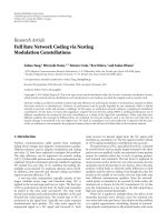
Figure 1: Two-way relay, a special case of the general model.
performance of different schemes is analyzed in the two-way
relay scenario in Section 5 and the related simulation
evaluation is presented in Section 6. Finally, we conclude the
paper with Section 7.
2. System Model
of them are selected by taking the tradeoff between the
number of links and the actual rate [9]. This opportunistic
scheduling, however, cannot exploit the full power of NC.
Recently, some initial efforts were made to fully exploit
rate adaptations in NC. Multiplicative NC was proposed
in [10] to better adapt code and modulation rates to
different links. However, it only applies to constant modulus
signals. Unconventional 5-ary modulation was introduced to
work together with QPSK in [11]. This makes modulation
complex and is difficult to extend to other modulations.
Compress and forward was studied in [12], with the
assumption that the relay is much closer to the sink than
nodes and has a much higher rate. Its application is limited
to multiple access up-link. XOR-based NC and physical
layer superposition coding were combined together to better
exploit rate adaptation in [13], however, at the cost of
significant power loss. Moreover, its performance is degraded
and approaches that of NC when relay links have similar
quality. Despite all these efforts, there is still no complete
solution to the rate mismatch problem.
In this paper, we focus on the bit level NC and propose
to achieve full rate network-coding (FRNC) on the broadcast
channel via nesting modulation constellations. With a crosslayer design, we exploit physical layer method as well. The
principle of dirty paper coding [14] indicates that a signal
known at the receiver is not interference at all and with suitable
coding the full capacity is achievable. As an analogy for
NC, when the a priori information is available, NC should
also achieve the highest rate over each link, in other words,
achieve the full rate on the broadcast channel. This is our
starting point. The basic idea is as follows: (i) at the relay
node, in order to combine packets together and transmit
them over links supporting different rates (modulations),
the low level constellation points are nested in the high
level constellation. In other words, a subset of the high level
constellation is used as the low level constellation, and this
subset depends on the design of NC. (ii) At the receiver side,
nodes merely supporting low level modulation first find
their constellation according to the a priori information
and then perform demodulation and decoding. In this way,
the highest rate of each link is used and the sum rate is
achieved over the broadcast channel. We further study the
effect of the limit in constellation size and suggest combining
FRNC with superposition coding (SC). Both the analysis
and simulation evaluation show that FRNC with SC is
significantly superior to the state-of-the-art solutions to the
rate mismatch problem.
The rest of the paper is organized as follows: the relay
model is presented in Section 2 and the reinterpretation
of NC as constellation mapping is addressed in Section 3.
In Section 4, the detailed procedures for achieving full
rate in network-coded transmissions are described. The
We consider a network with n nodes Mi , i = 1, 2, . . . , n, and
1 relay R. For the simplicity of description, we assume that
all nodes and R are synchronized and the transmissions are
done in terms of TDMA (it is possible to extend the proposed
scheme to other channel access methods such as CSMA.)
There are n flows. The ith flow from MiS to MiD goes through
the two-hop path MiS -R-MiD and the actual transfer of packets is via the relay R. The packet transfer is divided into two
stages: (a) multiple access stage where R collects packets from
all nodes. Each node MiS sends packet Pi to R in the ith slot,
using its optimal rate (modulation and coding). After the
data transmission, each node reports its receiving status of
packets to R, in a similar way as the COPE scheme [15]. Based
on such a feedback, R makes the NC scheduling, selecting a
subset of n1 nodes, each of which knows all packets involved
in the NC except its own desired packet. Without loss of
generality, in the following, we assume n1 equals n. Then after
n slots, MiD knows P1 , . . . , Pi−1 , Pi+1 , . . . , Pn . (b) Broadcast
stage where R forwards packets to all nodes. R transmits PΣ =
⊕i Pi (⊕ represents the bitwise exclusive or (XOR) operation)
to all nodes, and MiD recovers Pi by (⊕ j = i P j ) ⊕ PΣ . Hence,
/
n packets are exchanged in n+1 slots. A typical example for
the model is the local area wireless networks where nodes
exchange packets via their associated access point (R in the
model). A special case is n = 2, corresponding to the twoway relay in Figure 1. In this special case, each node uses
its transmitted packet as the a priori information and the
feedback of receiving status of packets is unnecessary.
Over each link, the rate can be adjusted by modulation
and coding. With coding rate c and modulation level m
(constellation size = 2m ), on average c · m bits can be
transmitted by each symbol. Generally, the modulation level
determines a rate range, within which the coding scheme
further fine adjusts the rate. Different modulation levels have
constellations with different sizes. But these constellations all
have the same normalized energy.
In the above model, NC is used at the second stage. We
focus on this stage and exploit joint design of modulation
and coding so that the highest rate of each link is realized in
the NC transmission. We take the following assumptions: (i)
R has collected enough data for each flow so that the zeropadding is unnecessary in the NC transmission, (ii) the a
priori information required for network decoding is available
at each node by recording the overheard packets, and (iii)
the relay node knows the channel state information of all
links. The key problem is how to realize full rate on all links
simultaneously.
3. Reinterpretation of Network Coding
In conventional bit level NC schemes, bits from different
flows are XORed together, channel coded, modulated, and
EURASIP Journal on Wireless Communications and Networking
M2 → R : a1 a0 = 01
At M1
(b1 b0 = 11 known a priori)
⊕
00 11 = 11; S3 → SA0
⊕
01 11 = 10; S2 → SA1
⊕
10 11 = 01; S1 → SA2
⊕
11 11 = 00; S0 → SA3
M1 → R : b1 b0 = 11
R → M1 , M2
⊕
a1 a0 b1 b0 = 10
0x
1x
S1 : 01
3
S3 : 11
1x
SA2 : 10
QPSK constellation
at R for NC transmission
1x
SB0 : 00
SA0 : 00
SB2 : 10
x0
x0
S2 : 10
0x
0x
x1
S0 : 00
At M2
(a1 a0 = 01 known a priori)
⊕
01 00 = 01; S1 → SB0
⊕
01 01 = 00; S0 → SB1
⊕
01 10 = 11; S3 → SB2
⊕
01 11 = 10; S2 → SB3
x0
x1
SA3 : 11
SA1 : 01
QPSK constellation
at M1 for decoding a1 a0
x1
SB1 : 01
SB3 : 11
QPSK constellation
at M2 for decoding b1 b0
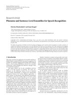
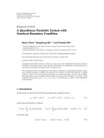
Figure 2: Reinterpretation of network-coding by modulation.
then transmitted. The receiver just works in the reverse way
to recover its information bits. Due to the linearity of both
channel coding and NC, their order can be exchanged [16].
In this paper, the NC operation is done after channel coding.
Although the NC is performed in the bit level, it can
be reinterpreted as a function of constellation mapping.
This is explained by an example shown in Figure 2 using
the typical QPSK constellation with gray codes. Assume R
relays a1 a0 (“01”) from M2 to M1 , and b1 b0 (“11”) from M1
to M2 , respectively. When relaying these bits, R combines
them together as “10” by XOR and transmits (S2 )QPSK .
M1 already knows b1 b0 (“11”). Exploiting this as the a
priori information, for all possible bits of a1 a0 , the NC
bits and corresponding signals can be computed locally at
M1 . These signals, when interpreted as the points for a1 a0 ,
construct a new QPSK constellation (SA0 SA1 SA2 SA3 )QPSK .
This constellation has the same size as (S0 S1 S2 S3 )QPSK but
with a different layout due to NC. In this way, the NC
function actually provides a mapping between constellations.
Instead of a fixed constellation in conventional modulations,
such a mapping depends on the a priori information and
changes for each symbol. The reinterpretation of NC can be
summarized as follows:
(i) R transmits F(P1,c , P2,c , . . . , Pn,c ) where Pi,c is the
channel-coded packet of the ith flow, and F involves
NC (XOR in conventional NC) and modulation.
(ii) At the receiver side, F −1 (api ) (api = ⊕ j = i P j,c
/
in conventional NC) provides the constellation for
demodulating Pi,c , where api is the a priori information at the ith receiver.
In conventional NC schemes, the constellations for
different flows have the same size and min-distance, and the
latter is the main factor that decides the rate. This forces the
relay node to transmit the XORed packet with the minimal
rate of all links so that all nodes can correctly recover the
XORed packet.
The above constellation mapping can be extended to support simultaneous use of modulations with different levels
(size and min-distance). Specifically, we use constellationcompatible modulations and nest the low level constellation
inside the high level constellation. For example, a subset
of four 16 QAM constellation points can be used as the
QPSK constellation so that over the broadcast channel QPSK
is used for one link while 16 QAM is used for the other
link in the two-way relay scenario. In other words, among
the links supporting different modulations, the highest
modulation level is always used as the container. Other low
level modulations use a subset of the high level constellation
as their constellations.
4. Full Rate Network Coding Protocol
In this section, we present the full rate network-coding
(FRNC) protocol. First the basic idea is explained with a
simple example. Then the idea is generalized. How to nest
constellations, how to find the actual constellation under
the NC operation, how to transmit at the relay, and how to
receive at the nodes are successively described in detail.
4.1. An Example Revealing the Basic Idea. With the two-node
(n = 2) scenario in Figure 1, we show how to use different
rates over different links in the network-coded transmission.
Assume that (i) links between R and M1 /M2 support rates
with c1 = 1/2, m1 = 2 (QPSK), c2 = 1/2, m2 = 4 (16 QAM),
respectively. On average, R can forward r1 = c1 · m1 = 1
bit/symbol to M1 and r2 = c2 · m2 = 2 bit/symbol to M2 . (ii)
The slot length is N = 2 symbols. Then 2 bits to M1 or 4 bits
to M2 can be transmitted in a single slot. (iii) The two bits
from R to M1 are P1,u = “10” and 4 bits from R to M2 are P2,u
= “1101”.
The transmit procedure is shown in Figure 3. At R, P1,u
and P2,u are channel-coded to P1,c = “1101” and P2,c =
“11100010”. The modulations for the two messages are QPSK
and 16 QAM, respectively. To transmit the two messages
together via NC, the QPSK constellation for P1,c is nested
in the 16 QAM constellation used for P2,c . The nesting is
realized by postcoding. In this example, by repetition codes
with rate = 1/2, P1,c is encoded to P1 = “11110011”, with the
4
EURASIP Journal on Wireless Communications and Networking
Table 1: Constellation conversion from 16 QAM to QPSK
(a3 a2 a1 a0 represents the a priori info, b1 b0 are the info bits to be
received).
a priori info a3 a2 a1 a0
QPSK constellation
(a3 a2 a1 a0 ⊕ b1 b1 b0 b0 )
0000
(S0 , S3 , S12 , S15 )16 QAM
0001
(S1 , S2 , S13 , S14 )16 QAM
0010
(S2 , S1 , S14 , S13 )16 QAM
0011
(S3 , S0 , S15 , S12 )16 QAM
0100
(S4 , S7 , S8 , S11 )16 QAM
0101
(S5 , S6 , S9 , S10 )16 QAM
0110
(S6 , S5 , S10 , S9 )16 QAM
0111
(S7 , S4 , S11 , S8 )16 QAM
1000
(S8 , S11 , S4 , S7 )16 QAM
1001
(S9 , S10 , S5 , S6 )16 QAM
1010
(S10 , S9 , S6 , S5 )16 QAM
1011
(S11 , S8 , S7 , S4 )16 QAM
1100
(S12 , S15 , S0 , S3 )16 QAM
1101
(S13 , S14 , S1 , S2 )16 QAM
1110
(S14 , S13 , S2 , S1 )16 QAM
1111
(S15 , S12 , S3 , S0 )16 QAM
same length as P2 = P2,c = “11100010”. The XORed sum of P1
and P2 is PΣ = “00010001”. Then PΣ is modulated with the
16 QAM constellation (using gray codes) shown in Figure 4,
and R transmits xΣ = (S1 S1 )16 QAM .
The receive procedure is shown in Figure 5. At the ith
node, the signal received from R is si (t). For simplicity, noise
and channel fading are ignored. In the same way as the relay
performs channel coding and post-coding, P1 = “11110011”
is calculated from P1,u at M2 , and P2 = “11100010” is
calculated from P2,u at M1 , and are used as the a priori
information in the network decoding stage.
Since s2 (t) has the same modulation level as the one
supported by the quality of link M2 R, decoding at M2 is the
same as usual. At first, PΣ = “00010001” is demodulated from
s2 . With P1 = “11110011” as the a priori information, P2,c
= P2 = “11100010” is obtained and then P2,u = “1101” is
channel decoded. s1 (t) has a higher modulation level than
the one supported by the quality of link M1 R. Therefore,
the decoding at M1 is a little more complex. The QPSK
constellation to be used at M1 depends on the a priori
information and has to be constructed from the 16 QAM
constellation. With repetition codes used in the post-coding
stage in this example, two bits b1 b0 carried in a QPSK symbol
are post-coded to b3 b2 b1 b0 = b1 b1 b0 b0 , corresponding to a
16-QAM symbol. With a3 a2 a1 a0 as the a priori information,
varying b1 b0 , the possible NC bits a3 a2 a1 a0 ⊕ b3 b2 b1 b0 and
the corresponding signals can be computed. Table 1 shows
the derived QPSK constellations for demodulating b1 b0 , with
the four a priori bits a3 a2 a1 a0 as an index.
At M1 , with P2 = “11100010” known a priori, for the first
symbol in xΣ , a3 a2 a1 a0 = “1110”, (S1 )16 QAM is to be demodulated with the QPSK constellation (S14 , S13 , S2 , S1 )16 QAM
Table 2: A comparison of the broadcast channel among three
schemes, for the scenario shown in Figure 1.
scheme
DF
NC (min rate)
FRNC (full rate)
rate
(r1 /2) + (r2 /2)
min (r1 , r2 ) · 2
r1 + r2
# transmitted bits
3
4
6
(refer to Table 1); for the second symbol in xΣ , a3 a2 a1 a0
= “0010”, (S1 )16 QAM is to be demodulated with the QPSK
constellation (S2 , S1 , S14 , S13 )16 QAM . Here, xΣ = (S1 S1 )16 QAM
logically corresponds to (S3 S1 )QPSK . It is demodulated to
P1,c = “1101” and converted to P1,u = “10” after channel
decoding. In this way network decoding is realized by the
constellation conversion.
A simple comparison on the broadcast channel, among
decode-and-forward (DF), bit level NC with minimal rate,
and FRNC, is summarized in Table 2. With DF, R uses one
symbol for each node and thus transmits 3 bits in total. With
NC, R transmits (min(ri ) · 2) · 2 = 4 bits. With FRNC, R
transmits ( ri ) · 2 = 6 bits using two symbols.
Although superposition coding handles links with different qualities as well, the proposed FRNC scheme is quite
distinct from it. Constellation nesting fully exploits the
power on each link by using the a priori information in
times of decoding. As a comparison, superposition coding
does not exploit the a priori information for decoding the
desired signal. Instead, the total power is divided into two
parts, most power for the base layer signal and little power for
the secondary layer signal, which results in significant power
loss in transmitting the secondary layer signal.
In the following sections, we extend the above idea to
more general cases and study the related post-coding scheme
and the decoding method.
4.2. Nesting Constellations. We first consider how to nest N1 QAM (we focus on the constellations in the form of grid,
extension to other forms of constellations is also possible.)
in N2 -QAM (N2 > N1 , Nk = (nk )2 = 2mk , k = 1, 2). A
simple way is to choose a subset of N2 -QAM constellation
points as the N1 -QAM constellation. We construct the N1 QAM constellation by dividing N2 -QAM into subsets. Let the
min-distance of N2 -QAM be d2 . The points of N1 -QAM with
a distance d1 = n2 /n1 · d2 to their neighbors are grouped into
the same subset. In this way, the N2 -QAM constellation is
divided into (n2 /n1 )2 subsets, each of which having the same
size N1 .
Choosing points for (non-QAM) BPSK requires one
more step: after choosing a subset for QPSK from the QAM
constellation, select two diagonal points from the QPSK
constellation for BPSK.
A single point of the N1 -point constellation can only
carry m1 information bits. But after nesting it inside the
N2 -constellation, its bit vector is extended to m2 bits. There
should be a bit-mapping. The only subset, which contains the
all-zero bit-vector, is used for bit mapping from m1 to m2 .
Figure 4 shows an example of dividing 16 QAM to find
QPSK constellations, where N2 = 16, m2 = 4, N1 = 4,
EURASIP Journal on Wireless Communications and Networking
5
Info bits
to M1
Info bits
to Mn
Get Nrn bits
Get Nr1 bits
Pn,u = 1101
P1,u = 10
CH-COD
CH-COD
P1,c = 1101
(QPSK)
Pn,c = 11100010
(16 QAM)
···
POST-COD
POST-COD
Pn = 11100010
⊕
P1 = 11110011
(16 QAM)
P∑ = P1
⊕
···
⊕
Pn = 00010001
MOD
x∑ = (S1 S1 )16 QAM
Figure 3: Coding and modulation at the relay node.
00xx
(−0.948)
S2 : 0010
01xx
(−0.316)
S6 : 0110
11xx
(0.316)
S14 : 1110
Table 3: Some bit mapping methods.
10xx
(0.948)
S10 : 1010
xx10
(0.948)
S3 : 0011
S7 : 0111
S15 : 1111
S11 : 1011
xx11
(0.316)
S1 : 0001
S5 : 0101
S13 : 1101
S9 : 1001
xx01
(−0.316)
S0 : 0000
S4 : 0100
S12 : 1100
S8 : 1000
xx00
(−0.948)
Figure 4: Nesting QPSK constellation in 16 QAM constellation.
m1 = 2. The 16 QAM constellation is divided into four
subsets: CS1 = (S0 , S3 , S12 , S15 ), CS2 = (S1 , S2 , S13 , S14 ), CS3 =
(S4 , S7 , S8 , S11 ), CS4 = (S5 , S6 , S9 , S10 ). CS = CS1 ∪ CS2 ∪ CS3 ∪
CS4 is the constellation for 16 QAM. QPSK may use any CSi
as its constellation point, although with a different layout
under NC.
Table 3 shows some bit mapping methods, where the N1
m1 -bit vectors are one-to-one mapped to N1 m2 -bit vectors
in the subset containing the all-zero vector. The left column
represents the nesting method, the second column is the
original bits to be transmitted with low level constellation,
and the right column shows the bit vectors in the nested
constellation. With the bit mapping, the bits of low-level
constellations are modulated to the subsets of high-level
Nesting Method
BPSK in QPSK
BPSK in 16 QAM
QPSK in 16 QAM
QPSK in 64 QAM
16 QAM in 64 QAM
Bits in low-level
constellation
0, 1
0, 1
00, 01
10, 11
00, 01
10, 11
0000, 0001
0010, 0011
0100, 0101
0110, 0111
1000, 1001
1010, 1011
1100, 1101
1110, 1111
Bits for sub-set in
container
constellation
00, 11
0000, 1111
0000, 0011
1100, 1111
000000, 000110
110000, 110110
000000, 000011
000101, 000110
011000, 011011
011101, 011110
101000, 101011
101101, 101110
110000, 110011
110101, 110110
modulation, and the function of post-coding in Figure 3 is
realized.
The constellation nesting may have SNR loss since the
min-distance of the nested constellation may be a little
less than that of the standard one. For example, with
normalized energy, the min-distance of two 16-QAM points
equals 0.6325. When nesting QPSK inside 16 QAM, the mindistance equals 0.6325 · 2 = 1.265, which is 0.97 dB less
than 1.414, the min-distance of normal QPSK constellation.
Table 4 shows the SNR loss, where the horizontal and vertical
labels stand for original constellations and container constellations, respectively. Although nesting QPSK in 16 QAM has
6
EURASIP Journal on Wireless Communications and Networking
P1,u = 10
For
M1
Pn,u = 1101
a priori
info
P 2 , . . . , Pn
CH-DEC
P1 , . . . , Pn−1
⊕
CH-DEC
⊕
Pn,c = 11100010
P1,c = 1101 ⊕
⊕
P 2 · · · Pn
DEMOD = 11100010
NC-DEC
QPSK
constellation
P1
⊕
For
Mn
···
⊕
Pn−1
= 11110011
P∑ = 00010001
NC-DEC
s1 (t)
a priori
info
DEMOD
x∑ = (S1 S1 )16 QAM
sn (t)
Figure 5: Recover information bits at the nodes.
Table 4: Potential SNR loss in constellation conversion.
QPSK
16 QAM
64 QAM
256 QAM
BPSK
0
−0.97 dB
−1.18 dB
−1.23 dB
QPSK
16 QAM
64 QAM
Table 5: SNR threshold for rate adaptation (for a message
consisting of 4800 symbols).
SNR (dB)
−0.97 dB
−1.18 dB
−0.26 dB
≥7.0
−0.21 dB
−1.23 dB
−0.05 dB
≥7.6
≥10.4
SNR loss of about 0.97 dB, nesting other constellations has
little SNR loss (0.05 dB for 64 QAM in 256 QAM) or no SNR
loss (0 dB for BPSK in QPSK) at all. The SNR loss is taken
into account when choosing rate (modulation and coding)
according to SNR.
≥12.8
≥17.0
≥21.0
≥23.4
≥26.8
≥28.0
4.3. Actual Constellation under Network Coding. The next
important issue is to find the actual constellation layout
under NC. We explain this with Figure 4 as an example. It can
be easily verified that the division has the following property:
∀P1 ∈ CS1 , ∀ap1 ∈ CS, if ap1 ∈ CSi ,
then P1 ⊕ ap1 ∈ CSi .
(1)
Equation (1) shows that, for a point ap1 in the high level constellation (ap1 ∈ CS), if ap1 is in the subset CSi , it maps CS1
to CSi by the NC operation. The actual constellation layout of
CSi for demodulating P1 is determined by P1 ⊕ ap1 , with api
known a priori at the receiver. Although a constellation under
NC changes with the a priori information, the min-distance
for N1 -QAM, under all the a priori information, remains the
same: d1 = n2 /n1 · d2 .
As for the example in Figure 1, using the third row
of Table 3, two bits b1 b0 are post-coded to b3 b2 b1 b0 . With
a3 a2 a1 a0 ⊕ b3 b2 b1 b0 being received and api = a3 a2 a1 a0
known a priori at M1 , the QPSK constellation for demodulating b1 b0 is looked up in Table 1 by using a3 a2 a1 a0 as an index.
For example, when a3 a2 a1 a0 = “1110”, (S14 , S13 , S2 , S1 )16 QAM
is equivalent to (S0 , S1 , S2 , S3 )QPSK . Since the derived QPSK
constellation depends on the a priori information, it changes
for each symbol. Recovery of other constellations can be
done in a similar way.
Modulation and coding
BPSK (1/2)
BPSK (3/4)
QPSK (1/2)
QPSK (3/4)
16 QAM (1/2)
16 QAM (3/4)
64 QAM (2/3)
64 QAM (3/4)
256 QAM (2/3)
256 QAM (3/4)
Bit/Sym
0.50
0.75
1.00
1.50
2.00
3.00
4.00
4.50
5.33
6.00
4.4. Encoding/Modulation at the Relay. Figure 3 shows the
transmit procedure at relay R. For each flow fi , according to
the SNR of its relay link, R finds the transmit rate ri from
an empirical SNR-rate table shown in Table 5. SNR loss due
to constellation nesting is considered in this process: the rate
corresponding to SNR is lowered if SNR loss makes this rate
improper.
Assume, without loss of generality, that rates, r1 , r2 ,
. . . , rn , over links from R to M1 , M2 , . . . , Mn , are in the
increasing order, that is, r1 ≤ r2 · · · ≤ rn . Each ri = ci · mi
corresponds to a coding rate ci and a modulation level mi .
mi , i = 1, 2, . . . , n, are also in the increasing order.
Transmission at R is done by the following steps.
(i) Every time R transmits a fixed number of symbols, N.
For each flow fi , the number of information bits that
can be transmitted is N · ri . These information bits
form a frame Pi,u . On Pi,u channel coding with rate ci
is performed, which generates Pi,c . Pi,c , i = 1, 2, . . . , n,
have different length in bits.
(ii) In order to transmit Pi,c , the constellation mi should
be nested in mn . This is done by the bit mapping
(POST-COD) according to Table 3, which maps mi
to mn and encodes Pi,c to Pi .
EURASIP Journal on Wireless Communications and Networking
(iii) Pi , i = 1, . . . , n are XORed together as PΣ = ⊕i Pi .
PΣ , modulated to signal xΣ with constellation mn ,
is transmitted to all nodes with out-of-band rate
information ri , i = 1, 2, . . . , n (each node only records
the information bits on overhearing packets from
nearby nodes to the relay. With the rate information
from the relay, the node performs the same channel
coding/post coding as the relay and calculates the
coded bits as the a priori information for network
decoding.)
4.5. Demodulation/Decoding at the Receiver. Figure 5 shows
the demodulation and decoding procedure at all nodes. At
the ith node, the signal received from R is
si (t) = hi · xΣ (t) + ni (t),
(2)
where hi is the channel gain and ni (t) is zero mean additive
white Gaussian noise (AWGN).
A node Mi , supporting the used constellation (mi =
mn ), performs soft demodulation and calculates symbol loglikelihood ratio (LLR) [17] and then converts to bit LLR. The
bit LLR corresponds to XORed bits from all flows. With the
a priori information bits (api = ⊕ j = i P j ) known in advance,
/
the LLR of desired bits can be recovered and then channel
decoding is performed. The whole procedure is shown in the
right side of Figure 5.
For a receiver Mi requiring a lower constellation (mi <
mn ), at first the low-level constellation is derived by exploiting the a priori information, as described in Section 4.3.
This derivation of constellation is actually network decoding.
Then the received signal is demodulated with the derived
constellation and later channel decoded to recover the bits,
as shown in the left side of Figure 5.
7
coding scheme, (iv) NC + SC, the iPack scheme in [13], (v)
FRNC, and (vi) FRNC + SC. In the analysis, we assume (i)
2
each channel has zero mean AWGN noise with variance σn ;
(ii) channel gain of the link Mi -R is hi ; (iii) each symbol
has normalized energy and the SNR over each link is γi =
2
|hi |2 /σn , (iv) the packet length is infinite.
5.1. Capacity without Fading. With FRNC, the capacity of
the broadcast channel reaches the sum rates of the two
links (here, we ignore SNR loss in constellation nesting
for simplicity. the SNR loss is taken into account in the
simulation evaluation),
cFRNC γ1 , γ2 = log2 1 + γ1 + log2 1 + γ2 .
(3)
The capacity of DF is half of that of FRNC,
cDF =
cFRNC
.
2
(4)
The capacity of NC is
cNC γ1 , γ2 = 2 · log2 1 + min γ1 , γ2 .
(5)
Next we calculate the throughput of NC + SC, SC,
FRNC + SC, where SC is involved. Assume, without loss of
generality, that γ2 ≥ γ1 . Part (0 ≤ α ≤ 1) of the power
is used to transmit the base layer signal xΣ (the NC coded
message in NC + SC, the plain message in pure SC, the FRNC
coded message in FRNC + SC), and the remaining power
(1 − α) is used to transmit the secondary signal x2 to M2 .
The transmitted signal is
√
√
x(t) = 1 − α · x2 + α · xΣ .
(6)
At Mi , SNR of the received base layer signal (xΣ ) is
4.6. Discussion: Constellation Size Limit. FRNC requires that
constellation size should be large enough so that high rate
can be used at high SNR. In practical systems, there is
a constraint on the constellation size which restricts the
maximal rate. The maximum of constellation size, referred
to as the constellation size limit hereafter, confines the
performance of FRNC. In such cases, FRNC can be used
together with superposition coding (SC) to fully exploit the
transmit power. NC is already used together with SC in [13],
where the fine scheduling is used to combine links with
almost the same gain and apply NC to them. For links with
quite different gains, SC is applied. But such a scheduling
heavily depends on the actual topology. As a comparison, we
replace the NC in [13] with FRNC and suggest FRNC + SC,
which is analyzed in Section 5.
5. Performance Analysis of Two-Way Relay
In this section, we analyze the performance of different
schemes under the two-way relay scenario shown in Figure 1.
Six schemes are compared here. (i) DF, the decode-andforward scheme, (ii) NC, the normal bit level NC scheme
with minimal rate constraint, (iii) SC, the superposition
γi =
α · γi
α · |hi |2
=
.
2
(1 − α) · γi + 1
(1 − α) · |hi |2 + σn
(7)
Since γi is an increasing function of γi , min(γ1 , γ2 ) = γ1 and
the rate used for the NC coded message is determined by γ1 .
At M2 , after perfect interference cancellation, the SNR of the
secondary layer signal is
γ2 =
(1 − α) · |h2 |2
= (1 − α) · γ2 .
2
σn
(8)
The throughput of NC + SC under given γ1 , γ2 , and α, is
cNC + SC γ1 , γ2 , α = 2 log2 1 + γ1 + log2 1 + γ2
= 2 log2 1 + γ1 − 2 log2 1 + (1 − α) · γ1
+ log2 1 + (1 − α) · γ2 .
(9)
By differentiating cNC + SC (γ1 , γ2 , α) with respect to α, its
maximum can be obtained at α = 1−(1/γ1 −2/γ2 ). To achieve
8
EURASIP Journal on Wireless Communications and Networking
the maximal capacity, the power allocation should be done as
follows:
2γ1 > γ2 ≥ γ1 ,
1
2
−
,
γ1 γ2
α=1−
γ1 ≥ 1, γ2 ≥ 2γ1 or
1 > γ1 ≥ 0,
α = 0,
2γ1
> γ2 ≥ 2γ1
1 − γ1
1 > γ1 ≥ 0, γ2 ≥
(10)
2γ1
.
1 − γ1
= log2 1 + γ1 − log2 1 + (1 − α) · γ1
+ log2 1 + (1 − α) · γ2 .
(11)
This is a decreasing function of α and reaches its maximum
when α approaches 0. With the constellation size limit in
practical systems, over the link M2 -R, all SNR greater than
a certain threshold γmax supports the maximal rate. When
γ2 is large enough, it is sufficient to choose α so as to satisfy
(1 − α) · γ2 ≥ γmax . The rest of the power can be used for the
SC transmission over the link M1 -R.
As for FRNC + SC, the FRNC coded message replaces xΣ
in (6), and its capacity is as follows:
cFRNC + SC γ1 , γ2 , α
= log2 1 + γ1 + log2 1 + γ2 + log2 1 + γ2
= log2 1 + γ1 − log2 1 + (1 − α) · γ1 + log2 1 + γ2 .
(12)
It is interesting to see that the power allocation has no
capacity loss over the link R-M2 . The only loss compared
with FRNC is the part log2 (1+(1 − α) · γ1 ) over the R-M1 link,
which approaches 0 as α approaches 1. cFRNC+SC (γ1 , γ2 , α)
is an increasing function of α. Without constellation size
limit, α should be set to 1, and FRNC + SC degenerates to
FRNC. With the constellation size limit, devoting full power
to transmitting the FRNC coded packet is unnecessary.
Therefore, the SC coding should be used and γ2 is divided
into two parts, γ2 and γ2 . The optimal power allocation
policy is as follows:
γ2 ≤ γmax
γmax
γ2 + 1
·
,
otherwise
γmax + 1
γ2
γmax
2
α=1−
,
γ2 ≥ γmax + 2 · γmax .
γ2
10
5
0.2
DF
NC
SC
cSC γ1 , γ2 , α = log2 1 + γ1 + log2 1 + γ2
α=
15
0
The capacity of the pure SC is as follows:
α = 1,
Throughput (Mbps)
α = 1,
20
(13)
The power allocation can be explained as follows: (i) when
γ2 is small enough (γ2 ≤ γmax ), all power (α = 1) should be
used for FRNC since its rate is not saturated yet. (ii) As γ2
gets greater than γmax , α should be set to satisfy γ2 = γmax .
0.4
0.6
Normalized dist
0.8
NC + SC
FRNC
FRNC + SC
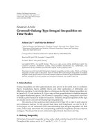
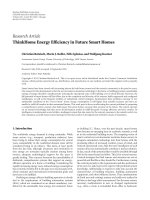
Figure 6: Throughput achieved by different schemes on the broadcast channel-effect of relay position for two way relay (theoretical
calculation, no constellation size limit).
The maximal rate is used over link M2 -R for FRNC, and the
extra power is used for the SC transmission over the link M2 R. (iii) If γ2 is very large, both the FRNC and SC transmission
reach the maximal rate over the link M2 -R, and α is chosen
to satisfy (1 − α) · γ2 ≥ γmax for the SC transmission. The
rest power is used in improving the FRNC rate over the link
M1 -R.
5.2. Capacity with Fading. Next we consider the effect of
fading and assume each channel experiences block Rayleigh
fading. γi follows the exponential distribution: fγi (γi ) =
1/γi · e−γi /γi , and the joint distribution is f (γ1 , γ2 ) =
fγ1 (γ1 ) · fγ2 (γ2 ). The average throughput can be calculated
by numerical integration.
With a two-way relay scenario similar to the one shown in
Figure 1, we study how the position of the relay node affects
the system performance. Adjusting the position of R between
M1 and M2 changes the normalized distance dM1 R /dM1 M2 .
Average SNR (γi ) of links M1 R and M2 R is calculated from
the normalized distance dM1 R /dM1 M2 according to the tworay model [18] with the path loss exponent (equaling 3 in
the simulation). When R lies in the middle of M1 and M2 ,
the average SNR of both relay links equals 20 dB. α is set to
the optimal value for schemes employing SC.
Figure 6 shows the average throughput of different
schemes, where there is no limit on constellation size. The
curve of FRNC + SC overlaps with that of FRNC. Both
outperform other schemes. As analyzed before, SC in NC +
SC only works under certain conditions. When the relay is
near the middle point, the difference in link quality is not
very large. NC + SC degenerates to NC, as is clear when the
distance equals 0.5. Without constellation size limit, the best
link is always chosen in SC, and the two-way communication
becomes unidirectional. The performance of NC is greatly
affected by the min-rate, especially when the relay is away
from the middle point and the difference in link quality
becomes large. Due to the effect of fading, two links with
EURASIP Journal on Wireless Communications and Networking
9
80
Throughput (Mbps)
Throughput (Mbps)
80
60
40
20
0
0.2
0.4
0.6
Normalized dist
DF
NC
SC
1
CDF
0.8
0.6
0.4
0.2
DF
NC
SC
20
0.2
0.4
0.6
Normalized dist
FRNC (64 QAM)
FRNC (256 QAM)
NC + SC
FRNC
FRNC + SC
40
60
80
Throughput achieved on broadcast channel (Mbps)
40
0
0.8
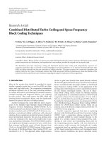
Figure 7: Throughput achieved by different schemes on the broadcast channel-effect of relay position for two way relay (simulation
results, largest constellation is 256 QAM).
0
20
60
100
NC + SC
FRNC
FRNC + SC
Figure 8: Cumulative density function of throughput achieved on
the broadcast channel (normalized distance = 0.3 in Figure 7).
the same average SNR have different instantaneous SNR.
Therefore, FRNC/FRNC + SC outperform NC and NC + SC
even when the normalized distance equals 0.5.
6. Numerical Results
In this section, we evaluate the proposed FRNC and FRNC
+ SC schemes using Monte-Carlo simulations. Each slot
consists of 4800 symbols. Messages are coded by a 4-state
recursive systematic convolutional (RSC) code with the
generator matrix (1, 5/7). Modulation and coding schemes
shown in Table 5 are used. Altogether, 10 different transmit
rates can be supported. The number of information bits
in a message varies from 2400 bits to 28800 bits. Messages
are transmitted from R to nodes via different schemes and
decoded accordingly. In the evaluation, we focus on the
0.8
FRNC + SC (64 QAM)
FRNC + SC (256 QAM)
Figure 9: Throughput achieved by different schemes on the
broadcast channel-effect of relay position for two way relay.
broadcast channel, and compare FRNC, FRNC + SC against
DF, NC [3], NC with opportunistic scheduling (NCSched)
[9], SC, and NC + SC [13]. SNR loss in FRNC is taken
into account when choosing rates for transmissions. It
is assumed that each link experiences independent block
Rayleigh fading. Modulation constellations are adopted from
IEEE 802.11a and the related parameters (symbol period,
number of subcarrier) are used in calculating throughput
[19].
With the two-way relay scenario shown in Figure 1 and
the same setting as in Section 5.2, we compare the actual
throughput achieved by different schemes, with the practical
constellation size limit. Figure 7 shows the total throughput
of different schemes on the broadcast channel with respect
to the normalized distance, where the largest constellation is
256 QAM. Generally speaking, Figure 7 shows similar trend
as Figure 6. But with the limit in constellation size, some
differences do occur: (i) FRNC + SC outperforms FRNC,
(ii) at a small distance, FRNC and NC + SC have similar
performances, and (iii) the difference between FRNC +
SC and NC + SC gets larger than that in Figure 6. By
the optimal allocation of power between FRNC and SC,
the best performance is achieved in FRNC + SC under
all distances. When the distance equals 0.30, FRNC + SC
reaches the largest throughput gain, 25.8%, against NC +
SC. At this distance, FRNC + SC achieves a much larger
gain, 74.2%, against NC. The cumulative density function
of the throughput at this distance is shown in Figure 8. The
superiority of FRNC and FRNC + SC over other schemes is
very clear.
Figure 9 shows the effect of constellation size limit. When
the largest constellation is constrained to 64 QAM instead of
256 QAM, the performance of both FRNC + SC and FRNC is
degraded. But the performance of FRNC + SC is less affected,
where the extra-power is used in SC transmission than being
wasted in FRNC.
Next the effect of the number of nodes, n, is evaluated.
Average SNR of all relay links is fixed at 20 dB. In such
10
EURASIP Journal on Wireless Communications and Networking
References
Throughput (Mbps)
200
150
100
50
0
2
3
DF
NC
4
Number of nodes
5
6
NCSched
FRNC
Figure 10: Throughput achieved by different schemes on the
broadcast channel, effect of the number of nodes. (simulation
results, largest constellation is 256 QAM).
scenarios, SC can hardly be used. Therefore, only the
schemes without using SC are compared. Figure 10 shows
the throughput on the broadcast channel. DF transmits in
a TDMA manner. Therefore, it cannot benefit from the
increase in nodes and its throughput is almost a constant
value. On the other hand, NC, NCSched and FRNC all
benefit from the increase in flows more or less. Due to the
different capability in handling rate mismatch, the slopes
of three curves differ greatly. FRNC always has the highest
throughput because the rate mismatch problem is completely
solved and full rate is achieved.
7. Conclusions
Recently, network coding is widely studied for improving
the relay efficiency in wireless networks. Its performance,
however, is greatly limited by factors such as rate mismatch.
In this paper, we reinterpreted network coding as a mapping
between modulation constellations and extended this mapping to enable simultaneous use of different modulations in
network-coded transmissions. In this way, the highest rate
over each link can be used and the sum rate can be achieved
over the broadcast channel. As a result, the rate mismatch
problem is completely solved. The only shortcoming of the
proposed scheme is its SNR loss in nesting constellations.
This little SNR loss is acceptable if the throughput gain is
taken into account. We will further study the effect of the
direct link and the potential errors at relay node.
Acknowledgment
This research was performed under research contract of
“Research and Development for Reliability Improvement by
The Dynamic Utilization of Heterogeneous Radio Systems”,
for the Ministry of Internal Affairs and Communications,
Japan.
[1] F. H. P. Fitzek and M. D. Katz, Cooperation in Wireless
Networks: Principles and Applications, Springer, New York, NY,
USA, 1st edition, 2006.
[2] R. Ahlswede, N. Cai, S. Y. R. Li, and R. W. Yeung, “Network
information flow,” IEEE Transactions on Information Theory,
vol. 46, no. 4, pp. 1204–1216, 2000.
[3] P. Larsson, N. Johansson, and K. E. Sunell, “Coded bidirectional relaying,” in Proceedings of the IEEE 63rd Vehicular
Technology Conference (VTC ’06), vol. 2, pp. 851–855, July
2006.
[4] P. Popovski and H. Yomo, “Bi-directional amplification of
throughput in a wireless multi-hop network,” in Proceedings
of the IEEE 63rd Vehicular Technology Conference (VTC ’06),
vol. 2, pp. 588–593, July 2006.
[5] S. Zhang, S. C. Liew, and P. P. Lam, “Hot topic: physicallayer network coding,” in Proceedings of the 12th Annual
International Conference on Mobile Computing and Networking
(MOBICOM ’06), pp. 358–365, September 2006.
[6] S. Katti, S. Gollakota, and D. Katabi, “Embracing wireless
interference: analog network coding,” in Proceedings of the
ACM : Conference on Computer Communications (SIGCOMM
’07), pp. 397–408, August 2007.
[7] C. Hausl and J. Hagenauer, “Iterative network and channel
decoding for the two-way relay channel,” in Proceedings of the
IEEE International Conference on Communications (ICC ’06),
vol. 4, pp. 1568–1573, July 2006.
[8] S. Tang, J. Cheng, C. Sun, R. Miura, and S. Obana, “Joint
channel and network decoding for XOR-based relay in multiaccess channel,” IEICE Transactions on Communications, vol.
E92-B, no. 11, pp. 3470–3477, 2009.
[9] H. Yomo and P. Popovski, “Opportunistic scheduling for
wireless network coding,” IEEE Transactions on Wireless Communications, vol. 8, no. 6, Article ID 5089949, pp. 2766–2770,
2009.
[10] P. Larsson, “A multiplicative and constant modulus signal
based network coding method applied to CB-Relaying,” in
Proceedings of the IEEE 67th Vehicular Technology Conference
(VTC ’08), pp. 61–65, May 2008.
[11] T. Koike-Akino, P. Popovski, and V. Tarokh, “Denoising
maps and constellations for wireless network coding in twoway relaying systems,” in Proceedings of the IEEE Global
Telecommunications Conference (GLOBECOM ’08), pp. 3790–
3794, December 2008.
[12] G. Zeitler, R. Koetter, G. Bauch, and J. Widmer, “On quantizer
design for soft values in the multiple-access relay channel,” in
Proceedings of the IEEE International Conference on Communications (ICC ’09), June 2009.
[13] R. Alimi, LI. Li, R. Ramje, H. Viswanathan, and Y. R.
Yang, “IPack: in-network packet mixing for high throughput
wireless mesh networks,” in Proceedings of the 27th IEEE Communications Society Conference on Computer Communications
(INFOCOM ’08), pp. 66–70, April 2008.
[14] M. H. M. Costa, “Writing on dirty paper,” IEEE Transactions
on Information Theory, vol. IT-29, no. 3, pp. 439–441, 1983.
[15] S. Katti, H. Rahul, W. Hu, D. Katabi, M. M´ dard, and
e
J. Crowcroft, “XORs in the air: practical wireless network
coding,” in Proceedings of the Conference on Computer Communications (SIGCOMM ’06), pp. 243–254, 2006.
[16] L. Xiao, T. E. Fuja, J. Kliewer, and D. J. Costello Jr., “Nested
codes with multiple interpretations,” in Proceedings of the 40th
Annual IEEE Conference on Information Sciences and Systems
(CISS ’06), pp. 851–856, 2007.
EURASIP Journal on Wireless Communications and Networking
[17] J. Hagenauer, L. Papke, E. Offer, and L. Papke, “Iterative
decoding of binary block and convolutional codes,” IEEE
Transactions on Information Theory, vol. 42, no. 2, pp. 429–
445, 1996.
[18] A. Goldsmith, Wireless Communications, Cambridge University Press, New York, NY, USA, 2005.
[19] IEEE Computer Society LAN MAN Standards Committee,
“LAN Medium Access Protocol (MAC) and Physical Layer
(PHY) Specification,” IEEE Std 802.11-2007, IEEE, 2007.
11