Báo cáo hóa học: " Research Article Intercell Radio Resource Management through Network Coordination for IMT-Advanced Systems Young-June Choi,1 Narayan Prasad,2 and Sampath " doc
Bạn đang xem bản rút gọn của tài liệu. Xem và tải ngay bản đầy đủ của tài liệu tại đây (1.06 MB, 13 trang )
Hindawi Publishing Corporation
EURASIP Journal on Wireless Communications and Networking
Volume 2010, Article ID 531347, 13 pages
doi:10.1155/2010/531347
Research Article
Intercell Radio Resource Management through
Network Coordination for IMT-Advanced Systems
Yo u n g - June C h o i ,
1
Narayan Prasad,
2
and Sampath Rangarajan
2
1
School of Information and Computer Engineering, Ajou University, Suwon 443-749, Republic of Korea
2
NEC Laboratories America, Princeton, NJ 08540, USA
Correspondence should be addressed to Young-June Choi,
Received 12 January 2010; Accepted 8 July 2010
Academic Editor: Mohammad Shikh-Bahaei
Copyright © 2010 Young-June Choi et al. This is an open access article distributed under the Creative Commons Attribution
License, which permits unrestricted use, distribution, and reproduction in any medium, provided the original work is properly
cited.
In IMT-Advanced systems, a cross-layer approach coupling network coordination and radio resource managements enables
mitigation of intercell interference and throughput improvement of cell-edge users. To facilitate coordination among base stations,
we propose a new radio-resource management framework where cell-edge users and cell-interior users are separately managed by
two different radio-resource managers. In the proposed framework, we address the issue of how to classify a user as cell-edge user
or cell-interior user, and how much radio resource the cell-edge users may occupy. We present a solution where a user switches the
user type so as to maximize overall network throughput subject to the condition that their own throughput does not decrease upon
switching. We verify our solution using analysis and simulation experiments where two or three BSs are coordinated to support
fractional frequency reuse or macrodiversity and demonstrate that our solution can guarantee superior cell-edge performance and
achieve a high network throughput.
1. Introduction
Recent developments in the area of wireless communica-
tions have witnessed a remarkable proliferation of wireless
technologies. While 3G and Be yond 3G cellular systems are
still being deployed, the IMT-advanced standards have set
a goal for an evolutionary growth towards 4G wireless net-
works. The potential candidate technologies for 4G networks
include 802.16m (WiMAX) and LTE-Advanced (3GPP).
These next-generation systems have adopted orthogonal
frequency division multiple access (OFDMA) as the air-
interface technology. In OFDMA systems, as neighboring
cells can reuse the same frequency, intercell interference is an
important problem that needs to be solved. Due to intercell
interference, cell-edge users may suffer low data rates (or
high error rates) even when the most robust modulation and
coding techniques are used.
To enhance the performance of cell-edge users in
OFDMA systems, frequency reuse techniques between neigh-
boring cells, have been developed. A simple technique is
to exploit a large frequency reuse factor such as 3. With
a reuse factor of one, all cells use all frequencies in which
case the intercell interference would be the highest. but cell
throughput is greatly reduced because each cell now can use
only 1/3 of the total available frequencies (channels). An
enhanced reuse technique is to use two reuse factors simulta-
neously; for example, cell-edge users are supported by a reuse
factor of 3 while the others use a reuse factor of 1 [1]. These
methods, however, limit flexibility in terms of radio-resource
utilization and cell deployment. For flexibility, dynamic
channel allocation has been widely examined (see [2, 3]
and references therein). In [2], dynamic channel allocation
is realized at both a radio network controller (RNC) and
at a BS which assign channels at the super-frame level and
frame-level, respectively. Dynamic channel allocation is also
referred to as dynamic fractional frequency reuse (FFR) [4],
and it is known that FFR can enhance cell-edge throughput
by about 15% [5] but at the expense of a reduced average cell
throughput.
Another technique to enhance cell-edge user perfor-
mance is macrodiversity. With macro-diversity, multiple BSs
can serve a user, thus making the link condition of cell-
edge users more reliable and robust [6]. Such a technique
has already been adopted in the IEEE 802.16 family of
2 EURASIP Journal on Wireless Communications and Networking
standards but the current macro-diversity schemes limit the
signaling formats (or space-time codes) that can be employed
by the coordinated BSs. An emerging technique that is
still in its infancy but has nevertheless generated enough
interest, is that of network MIMO. The concept of network
MIMO (a.k.a. multi-BS MIMO) to perform joint MIMO
transmission and reception between multiple coordinated
BSs and multiple users over the same radio resources [7,
8]. Network MIMO can be further divided into closed-
loop network MIMO, where coordinated BSs have access
to and exploit fast changing channel state information to
serve multiple users, or open loop network MIMO where
only average channel quality information is used to serve
the users. Note that open-loop network MIMO subsumes
macro-diversity schemes as special cases. In this paper we
present our solution to classify users by assuming a simple
macro-diversity scheme but our techniques can be readily
extended to other more general open-loop network MIMO
schemes.
Both dynamic FFR and macro-diversity require coordi-
nated RRM between neighboring BSs within the network.
We use RRM to refer to both radio resource management
and radio resource managers. If dynamic FFR is deployed
in the system, designated neighboring BSs of a cell to
which a certain cell-edge user is attached should avoid
concurrent transmission over the same set of channels. If
macro-diversity is used, one or more neighboring BSs should
serve a certain cell-edge user at the same time; this means
concurrent transmissions over the same set of channels from
multiple BSs to the same user is required. To handle such
requirements, the system needs network-level coordination
of radio resources through a cross-layer approach between
the network level and the radio level. In this paper, we
consider two different backhaul network architecture options
(hierarchical and flat) and develop a framework for network-
assisted RRM within these architectures so as to maximize
network throughput and enhance edge-user throughput.
In a conventional cellular architecture, network-level
coordination is easier to achieve as radio resources are
managed by an upper-level entity such as an RNC. For
example, as seen in [2], techniques such as dynamic FFR
and macro-diversity can be managed more easily at an
RNC since they required coordination among multiple BSs.
However, there are other techniques such as channel-aware
opportunistic scheduling [9–11] and closed-loop MIMO
operations that require real-time channel feedback from
users [12]. Wireless channel characteristics, specifically for
mobile users, fluctuate due to channel fading, and thus it
is required that channel feedback be delivered within one
slot/frame (5 msec in WiMAX systems and 1.67 msec in
cdma2000 EV-DO/HDR systems) duration [11]. In this case,
if RRM is implemented at a central entity, the two-hop
delivery of feedback information from a mobile station to the
upper-level entity through the BS may make this information
outdated and not usable.
In HDR and HSDPA systems [13, 14], where opportunis-
tic scheduling based on channel feedback plays a key role
in enhancing cell throughput; user and channel scheduling
is performed at the BSs. These systems do not implement
either dynamic FFR or macro-diversity both of which require
network-level coordination and are at odds with implement-
ing RRM functions at the BSs. In upcoming 4G systems
where techniques such as dynamic FFR and macro-diversity
are expected to be deployed together with conventional
techniques such as opportunistic scheduling and closed-loop
MIMO, it becomes imperative that a framework for RRM be
developed to enable such coexistence.
In this paper, we propose a two-level RRM framework.
We advocate the coexistence of two RRM entities, an upper-
level RRM and a lower-level RRM, within the backhaul archi-
tecture that connects the BSs. We separate users attached to
a BS into two groups; one group consists of users who are
classified as cell-edge users and the other consists of users
who are classified as cell-interior users. The RRM functions
for cell-edge users are handled by the upper-level RRM
whereas those for cell-interior users are handled by the lower-
level RRM. In a hierarchical backhaul architecture, we expect
the upper-level RRM to be deployed at the RNC whereas in
a flat backhaul architecture, each BS will deploy both the
upper and lower-level RRMs. In the latter case, the upper-
level RRM deployed within a BS will coordinate the RRM of
an attached cell-edge user with upper-level RRMs deployed
at neighboring BSs.
The classification of cell-edge and cell-interior users are
not based purely on geographic location as in conventional
frequency reuse techniques. We classify users as cell-edge
or cell-interior users with the goal of maximizing network
throughput subject to the condition that the user throughput
does not decrease upon switching; for example, a user at the
edge of a cell may still get classified as a cell-interior user if
such classification leads to higher network throughput with
no attendant loss in the user throughput or conversely if
such classification increases the user throughput without a
loss in the network throughput, this can happen due to the
multiuser diversity gain which is obtained when channel-
dependent scheduling is employed to serve cell interior
users. Furthermore, we also show that as compared to a
switching scheme which only aims to maximize the network
throughput, our classification scheme results in a better cell-
edge performance without a loss in network throughput.
Within the proposed framework, we address three main
problems: (1) initial user classification, (2) strategy to switch
users from one class to another subsequently, and (3) radio-
resource reservation in neighboring cells for users who are
classified as cell-edge users. We develop solutions for these
problems in situations where dynamic FFR and macro-
diversity mechanisms are available to cell-edge users. As
discussed earlier, these mechanisms require radio resources
from multiple neighboring cells.
The remainder of this paper is organized as follows.
In Section 2,weprovideabriefoverviewofthecurrent
framework for RRM support within a conventional 3G
cellular network architecture, which is hierarchical, as well as
a Beyond 3G system such as 802.16e (WiMAX) which is flat.
In Section 3, we describe the proposed two-level framework
for RRM and show its applicability within both a hierarchical
architecture and a flat architecture; 4G systems are expected
to implement the latter. The framework uses an upper-level
EURASIP Journal on Wireless Communications and Networking 3
ASN
GW1
ASN
GW2
RRC RRC
R4
R6 R6 R6
RRA
RRA
RRA
BS1
BS2
BS3
(a)
ASN
GW1
ASN
GW2
RRC
relay
RRC
relay
R4
R6 R6 R6
RRC
RRC
RRC
RRA
RRA
RRA
BS1
BS2
BS3
(b)
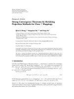
Figure 1: Access networks in WiMAX systems: (a) profile A, (b)
profile C.
RRM and a lower-level RRM to handle cell-edge and cell-
interior users, respectively. In Section 4, we introduce metrics
for describing a mechanism for classifying users as cell-edge
and cell-interior users, and explain initial user classification.
In Section 5, we provide algorithms for switching a user
between these two classes. In Section 7, simulation results
demonstrate that our classification algorithms improve cell-
edge performance. Section 8 provides conclusions from our
work.
2. Current RRM Framework
Traditionally, 2.5G and 3G cellular networks have employed
a hierarchical backhaul structure. Recently, Beyond 3G and
4G systems such as 802.16e and 802.16m (WiMAX) have
been evolving more towards a flat architecture. The WiMAX
standard has defined three different profiles for an access
service network (ASN) which is the backhaul network that
connects multiple BSs to an ASN gateway [15]. In Profile A,
which is now defunct, most radio resources are managed by
the ASN gateway as in traditional cellular networks and thus
has a hierarchical structure. In Profile B, the functionalities
of a BS and an ASN gateway are colocated on the same
platform/solution, which makes the architecture flat. Profile
C also defines a flat architecture where all the RRM functions
are performed at the BS.
Figure 1 presents the WiMAX ASN models for Profiles
A and C. In both cases, the interface (named R6) between
an ASN gateway and a BS is explicitly defined. In both these
profiles, a BS implements a RRA (radio resource agent), the
difference being where the RRC (radio resource controller)
is located. A RRA collects information on radio resources
and supervises the MAC and PHY functions including power
control. A RRC collects radio resource information from
RRAs and performs RRM. In Profile A, the RRC is located
at the ASN gateway whereas in Profile C, it is co-located with
the RRA at the BS; Profile C does support a RRC relay at the
ASN gateways to relay RRM messages that allows for inter-
profile RRM signaling between ASNs that are of type Profile
A, B, or C.
In the next section, we will use the WiMAX ASN archi-
tecture for Profiles A and C to motivate our two-level
RRM framework for a hierarchical architecture and a flat
architecture, respectively.
3. Proposed RRM Framework
3.1. Hierarchical Architecture. For a hierarchical backhaul
network architecture we propose that upper-level RRM that
manages cell-edge users be implemented at the ASN gateway
and lower-level RRM that manages cell-interior users be
implemented at the BSs. In this way, RRM functionality
is distributed between the ASN gateway and the BSs. The
motivation for this is as follows. As we discussed in an earlier
section, mechanisms such as fractional FFR and macro-
diversity require network-level coordination and an ASN
gateway is the appropriate place to manage users which are
cell-edge users and would benefit from these techniques.
Similarly, cell-interior users are most benefited by mech-
anisms such as channel-aware scheduling and closed-loop
MIMO both of which require real-time channel feedback
information which are available at the BS; thus, lower-level
RRM is best located at the BSs. Of course, our proposal
requires that cell-edge and cell-interior users be classified
appropriately, and this classification procedure is discussed
in the next sections.
Since the cell-interior users are controlled by BSs, ASN
gateways can relay data to/from those users without perform-
ing any RRM function. The cell-edge users are controlled
by ASN gateways and in this case the BSs can relay data
to/from those users without performing any RRM function.
In addition to RRM functions for the appropriate set of users,
common functions for all users at Layer 1 and Layer 2 are
performed at the BSs and Layer 3 functions are performed at
the ASN gateway.
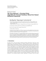
Figure 2 presents our proposal implemented within a
WiMAX system. In addition to the RRC (found in a Profile
A ASN-gateway), we also require an RRC relay at the
ASN gateway (similar to one found in a Profile C ASN-
gateway). The RRC at the ASN-gateway implements the
upper-level RRM functionality and controls the RRA at
the BS to manage cell-edge users. The RRC-relay allows
4 EURASIP Journal on Wireless Communications and Networking
RRC RRC
ASN
GW1
ASN
GW2
RRC
relay
RRC
relay
R4 R4 R4
R6 R6 R6 R6 R6 R6
RRC
RRC
RRC
RRA
RRA
RRA
BS1
BS2
BS3
Figure 2: The proposed access network applied to WiMAX systems.
communication between two RRCs that are each located
at the BSs. These RRCs at the BS implement the lower-
level RRM and communicate with the local RRA to manage
the cell-interior users. Note that RRCs in ASN gateways
communicate directly with each other to manage cell-edge
users who are the most likely to move across different ASN
gateways.
Now that we have discussed our two-level RRM frame-
work with respect to WiMAX architectures, we will hence-
forth use the terms upper RRC and lower RRC to denote
a generic upper-level RRM and a lower-level RRM, respec-
tively.
3.2. Flat Architecture. A two-level RRM framework can be
implemented within a flat backhaul network architecture as
well. Because there is no central coordinator to coordinate
the BSs (such as an ASN gateway), each BS handles both its
cell-edge users and cell-interior users; that is, an upper RRC
and a lower RRC coexist at each BS. Each cell-edge user will
have a serving BS to which it is attached that plays the role
of a coordinator; these users are managed in a decentralized
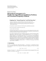
manner. Figure 3 illustrates implementation for upper and
lower RRCs within a flat architecture. Using a negotiation
protocol, a BS can designate a resource zone which is reserved
for the cell-edge users that it coordinates with its neighboring
BSs. This resource-zone specifies the different radio resources
within the cell controlled by this BS that are a priori reserved
to be used only by cell-edge users. When a cell-interior user
changes classification to a cell-edge user, the serving BS will
request reservation of radio resources for this user to the
neighboring BSs. If the neighboring BSs are able to allocate
enough resources, the user will be reclassified. The overall
operation will be the same as in the hierarchical architecture,
except the upper RRCs at neighboring BSs have to coordinate
with one another to handle cell-edge users.
Therefore, we develop an algorithm of deciding whether
auserwillbeservedbyanupperRRCoralowerRRC,which
is applicable regardless of network architecture.
3.3. Radio Resource Management. In the proposed frame-
work, both cell-edge and cell-interior users share radio
resources. This sharing can be enabled through a simple
mechanism where cell-edge users use radio resources first
and the cell-interior users use the residual radio resources.
This mechanism can be implemented, for example in
Cell-interior user Cell-edge user Cell-edge user Cell-interior user
Classification Classification
MAC and PHY processing
MAC and PHY processing
Lower
RRC
Upper
RRC
Upper
RRC
Lower
RRC
BS2BS1 Incoming packets
Figure 3: Downlink transmission in our flat architecture.
FCH and MAP
(Cell X)
PUSC
(Cell X)
PUSC
(Cell Y)
FUSC
(Cell X)
Optional FUSC
AMC
PUSC
Optional PUSC
Preamble
AMC
Downlink subframe UL subframe
Upper RRC Lower RRC
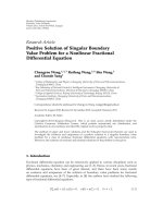
Figure 4: OFDMA frame with multiple zones in IEEE 802.16e
systems. In our proposed architecture, PUSC and FUSC are
assigned to upper RRC and lower RRC, respectively, over downlink
and subcarriers are orthogonally allocated to cell X and cell Y.
the WiMAX standards, using existing frame structure. In
a WiMAX (802.16e, 802.16m) system, the upper RRC can
write the downlink and uplink maps by allocating subcarriers
to cell-edge users first, and then the lower RRC can write the
residual map for cell-interior users. This is implementable
by the concept of multiple zones. IEEE 802.16 systems
define multiple zones where each zone is able to support
PUSC (partial usage of subcarriers), FUSC (full usage of
subcarriers), and AMC (adaptive modulation and coding)
modes, as shown in Figure 4. These zones can now be used
by upper RRC and lower RRC to assign radio resources to
cell-edge and cell-interior users, respectively. For example,
the PUSC mode can be used orthogonally by cell-edge users
whereas the FUSC or AMC mode can be used by cell-interior
users.
One concern is that an upper RRC could monopolize
radio resources available at a certain BS, thus starving its
cell-interior users. To avoid this, we could restrict the total
amount of zone/resource (e.g., number of subcarriers) that
an upper RRC can occupy. More dynamically, radio resources
can be adjusted according to a negotiation protocol between
upper and lower RRCs, and it is also feasible to design an
interactive RRM algorithm between both entities. The upper
RRC may take into account the amount of data to be served
at the lower RRC, or vice versa. Detailed protocols for such
negotiation are beyond the scope of this paper.
In the next sections, we first discuss a classification
algorithm for grouping users into cell-edge and cell-interior
EURASIP Journal on Wireless Communications and Networking 5
users. Following that, we develop an algorithm to dynam-
ically determine when a user should be reclassified. To
implement the initial classification algorithm, classifiers that
allocate a user to either an upper RRC or a lower RRC
have to be located at the ASN gateways or at the BSs in
the hierarchical architecture or flat architecture, respectively.
These classifiers determine the classification of new users as
well as the reclassification of existing users.
4. Initial User Classification and Metrics
In this section, we introduce metrics for classifying a user
as a cell-edge user to be assigned to an upper RRC and also
describe the initial classification of a new user.
4.1. Computation of User Capacities. We w oul d li ke to
determine the capacity a user can achieve when it belongs
to the lower RRC (cell-interior user group) or an upper RRC
(cell-edge user group). For simplicity, we suppose that a user
is able to measure their average signal-to-interference-plus-
noise ratio (SINR) as well as the average signal strengths
from one dominant neighboring BS and their serving BS,
respectively. In the following, we only deal with the case
where a cell-edge user is served by at most two BSs, since it
is easy to extend the analysis to the case where three or more
BSs can serve the user.
4.1.1. Capacity of Cell-Interior Users. Consider a specific
lower RRC user in cell 1 and assume that it is served only
by BS 1 without any cooperation by neighboring BSs. Let C
1
denote the resulting downlink capacity per unit resource and
let S
1
denote the average received signal strength from BS 1
at the user of interest. Further, let the dominant interfering
neighboring BS be indexed by 2 with I
2
denoting the average
received signal strength from BS 2 at the user of interest.
Next, let I
o
be the average interference to the user (which is
in cell 1) generated by neighboring BSs other than BS 2 and
let N be thermal noise variance. Then, the average received
SINR of the user is given by S
1
/(I
2
+ I
o
+ N). C
1
is a function
of this average SINR, and can be computed as
C
1
= log
1+
S
1
I
2
+ I
o
+ N
.
(1)
Letting γ
1
= S
1
/(I
o
+ N)andγ
2
= I
2
/(I
o
+ N), we can rewrite
C
1
as
C
1
= log
1+
S
1
γ
2
(
I
o
+ N
)
+ I
o
+ N
=
log
1+
γ
1
γ
2
+1
.
(2)
Note that the average SINR here is a function of the distance-
dependent path-loss and possibly large-scale shadow fading
but not of the small scale fading which changes on a much
finer time scale and is assumed to be averaged out.
4.1.2. Capac ity of Cell-Edge Users. Now consider two cases
where the cell-edge users are supported by, (a) fractional
frequency reuse, and (b) macro-diversity. In each case, no
opportunistic scheduling is employed and the users are
assigned rates based on their average SINRs.
(a) Dynamic FFR—in this case, to mitigate the interfer-
ence from a dominant neighboring cell at a particular
cell-edge user, the two BSs (serving BS as well as the
dominant interfering BS) are coordinated such that
the dominant neighboring BS will not use a certain
quantity of resources that is allocated to the cell-
edge user. As interference from the neighboring BS
is eliminated, the user can achieve a better capacity.
In particular, in the above example, I
2
is removed so
the user’s capacity achieved by the cooperation of BSs
1and2viaFFR,denotedbyC
1,2
, is expressed as
C
1,2
= log
1+
S
1
I
o
+ N
=
log
1+γ
1
.
(3)
(b) Macro-diversity—we consider Alamouti’s space-
time coding [16] for supporting downlink macro-
diversity. That is, the serving BS and the dominant
neighboring BS transmit two signals y
1
and y
2
at the
same time over the same frequency band, followed
by
−y
∗
2
and y
∗
1
. The transmissions from the two BSs
can be coherently combined using a simple receiver
[16]. Then, if the user is served by an upper RRC for
macro-diversity, their capacity will be given by
C
1,2
= log
1+
S
1
+ I
2
I
o
+ N
=
log
1+γ
1
+ γ
2
,
(4)
Obviously, C
1,2
in the two cases is higher than C
1
given
in (1),butsomeamountofresourcefromBS2needstobe
additionally provisioned for this user. It is possible to obtain
orthogonal space-time codes for three transmit antennas,
which in our case correspond to the antennas at the three
neighboring BSs. From [17], it can be inferred that the
resulting capacity is given by
C
1,2,3
(
k
)
=
3
4
· log
1+
S
1
+ I
2
+ I
3
I
o
+ N
. (5)
where I
2
and I
3
are the received signal strengths from two
neighboring BSs, and I
o
is the interference from neighboring
BSs other than those two BSs.
4.2. Computation of Throughput. The throughput of a cell-
interior user i in cell x is denoted by T
x
(i) and it can
be expanded as T
x
(i) = α(i)C
x
(i), where C
x
(i)denotes
the average capacity of the interior user i in cell x. α(i)
denotes the average ratio of resource allocated to user i
(e.g., the average ratio of slots or quantity of resource in
the frequency and time domains). Similarly, the throughput
of a cell-edge user i managed by the cooperation of BS x
and BS y is denoted by T
x,y
(i) and it can be expanded as
T
x,y
(i) = α(i)C
x,y
(i), where the average capacity C
x,y
(i)can
be computed as in (3)or(4) depending on whether FFR or
macro-diversity is employed. Note that each cell expends a
fraction of its available resources to serve the cell-edge users.
6 EURASIP Journal on Wireless Communications and Networking
The assignment of α’s relies on a scheduling policy
employed at the BSs. We do note that while user k is
managed by the lower RRC, α(k) may be adjusted by the
scheduling policy used or by the reclassification of other
users. On the other hand, the ratio α for a cell-edge user
is determined when the user is admitted into the network
as a cell-edge user or when the user is switched from the
lower RRC to the upper RRC. This computation will be
illustrated in the sequel. However, we assume α(k)tobea
constant value while user k is being managed by the upper
RRC. This simplifying assumption is made because resource
rearrangement for such users entails complex calculation
involving all the combinations of pairs of neighboring BSs.
To summarize, α(k) changes in the following cases.
(i) α(k) can decrease, if user k is managed by the lower
RRC and a new user requiring the cell resource
arrives.
(ii) α(k) can increase, if user k is managed by the lower
RRC and some resource is freed due to the departure
of an existing user who occupied the cell resource.
(iii) α(k) can increase or decrease, if user k switches the
serving RRC from a lower RRC to an upper RRC, or
vice versa.
(iv) Besides, α(k) is forced to change by a hand-off that
occurs regardless of the classification of the user.
Let β
x
be the ratio of resource in cell x allocated for cell-
edge users. β
x
can then be expressed as
β
x
=
y∈V
x
i∈U
x,y
α
(
i
)
,
(6)
where U
x,y
is the set of cell-edge users which are managed
by the cooperation of BSs x and y,andV
x
is the set of BSs
which cooperate with BS x (i.e., its neighboring BSs). BS x
will use the remaining resource 1
− β
x
for its cell-interior
users. We further assume that β
x
≤ β
max
in order to avoid
monopolization of the resources by the upper RRC.
4.3. Initial User Classification. A new user is admitted to the
system as a cell-edge or a cell-interior user. We consider
a simple scheme that guarantees a minimum throughput
T
min
(i) given by user i’s QoS requirement
T
x
(
i
)
≥ T
min
(
i
)
; T
x,y
j
≥
T
min
j
, ∀x, y, i, j.
(7)
The capacity of a new user n, C
x
(n), upon admission as a cell-
interior user in cell x is first estimated. Similarly, the capacity
C
x,y
(n) of the user upon admission as a cell-edge user served
by BSs x and y is also computed using (3)or(4). Then, the
user can be admitted as a cell-interior user by BS x only if its
minimum throughput requirement can be met, that is, only
if
i∈L
x
T
min
(
i
)
C
x
(
i
)
+
T
min
(
n
)
C
x
(
n
)
≤ 1 − β
x
− δ,
(8)
where L
x
is the set of cell-interior users in cell x and δ is
a margin for absorbing the change of some users’ average
capacities or accepting hand-off users; for our discussion, δ
is considered to be a design parameter. If user n is admissible
in BS x as a cell-interior user, a ratio α(n) is determined
according to the scheduling policy adopted by BS x.Once
α(n) is determined, the classifier (or admission controller)
checks if there exists an α
(n) acceptable by BSs x and y
for some y
∈ V
x
(using our upward RRC switch algorithm
in Section 5)whichcanleadtobettersystemanduser
throughputs. If such an α
(n) exists, the user is admitted as
a cell-edge user which is served by BSs x and y; otherwise
it is admitted as a cell-interior user which is served by
BS x.
Notice that in (8), we have implicitly assumed that the
throughput of an existing interior user i in cell x does not
change upon addition of a new user. However, when channel
dependent scheduling is employed, users may achieve a
greater throughput due to a larger multiuser diversity gain.
Thus, (8) is a conservative condition for admitting a new
user. In general, for channel dependent scheduling, the
increase in throughput with the addition of a new user or the
decrease in throughput with the deletion of another interior
user, is small when the number of interior users is sufficiently
large (10 or more verified in simulations). Henceforth, in
the case of channel dependent scheduling, we will assume
asufficiently large population of interior users in each cell
and ignore this change in the average capacity of an interior
user.
5. Strategy for User Reclassification
We now derive the condition for reclassifying users and
switching them from upper RRC to lower RRC or vice versa.
Users that do not satisfy these conditions will, by default,
not be reclassified. The objective behind reclassifying users
is to maximize the sum throughput over all the users in
the network covered by an ASN gateway (or a set of BSs
deployed for cooperation) subject to a minimum throughput
guarantee for each user. In particular, each user is allocated
to either a lower RRC or an upper RRC to meet the following
objective:
max
⎡
⎣
x∈N
i∈L
x
T
x
(
i
)
+
x,y∈N
j∈U
x,y
T
x,y
j
⎤
⎦
T
x
(
i
)
≥ T
min
(
i
)
; T
x,y
j
≥
T
min
j
, ∀x, y, i, j,
(9)
where N is the set of BSs within the domain. Further,
this reclassification is also subject to the condition that the
switching (reclassified) user’s throughput must not decrease.
We are now ready to propose our reclassification strategy
in which a user is allowed to switch only if both its own
throughput as well as the system throughput do not decrease
and at-least one of them strictly increases.
5.1. Upward RRC Switch. We first consider an upward RRC
switch algorithm, when user k tries to switch their RRC from
a lower RRC to an upper RRC. Assume that the user is being
served by cell 1 and the current ratio α for the user is α(k).
EURASIP Journal on Wireless Communications and Networking 7
Suppose that user k’s ratio changes to α
(k) after the RRC
switch, when he is supposed to be managed by BSs 1 and 2.
User k will accept the RRC change when their throughput
becomes higher by changing the RRC, so the first condition
for reclassification is
α
(
k
)
C
1,2
(
k
)
− α
(
k
)
C
1
(
k
)
≥ 0.
(10)
Since α
(k)C
1,2
(k) ≥ α(k)C
1
(k) ≥ T
min
(k), the condition in
(10) will ensure that the minimum throughput requirement
will also be satisfied postswitching.
Next, we consider the impact of switching on system
throughput which is more involved. In particular, there are
three factors that must be accounted for.
(i) The Throughput Loss in Cell 2. Notice that user k
postswitching will take an additional resource α
(k)from
BS 2 which could have been used for other users in that
cell if it had not been used for dynamic FFR or macro-
diversity. However, it is very hard to precisely estimate this
throughput loss since it depends on the cell 2’s scheduling
rule. Consequently, we use a simple way to quantify this loss
as α
(k) · C
2
,whereC
2
is the average per-user capacity of cell
2’s interior users. Note that with our assumption of infinitely
backlogged traffic, cell-interior users of any BS will always
fully utilize the available resources.
(ii) The Throughput Change in Cell 1. The throughput of
the current serving cell (cell 1) can change due to switching
in the following manner. First, if α
(k) <α(k), the residual
part α(k)
− α
(k) will be distributed among cell 1’s interior
users and together they will achieve an average throughput
gain of (α(k)
− α
(k)) · C
1
,whereC
1
is the average per-
user capacity of cell 1’s interior users (excluding user k).
Otherwise, that is, if α
(k) >α(k), cell 1’s interior users will
lose an average throughput of (α
(k) − α(k)) · C
1
. In either
case, the net throughput change in cell 1 is expressed by
(α(k)
− α
(k)) · C
1
.
(iii) System Constraints. We must ensure that the switch-
ing operation does not violate the minimum throughput
requirement of any user or the maximum limit on the
resource ratio reserved for cell-edge users in any cell.
Specifically, if either β
1
+ α
(k)orβ
2
+ α
(k)isgreater
than β
max
, or the additional resource α
(k) taken from BS
2orα
(k) − α(k) taken from BS 1 (when α
(k) >α(k))
jeopardizes the minimum allocation for users in L
2
or L
1
−
{
k}, user k cannot be allowed to use α
(k) by the upper
RRC.
Thus, the first two conditions dictate that a postswitching
ratio α
(k) chosen to maximize the network-side throughput
in (9), should satisfy
α
(
k
)
C
1,2
(
k
)
− C
1
− C
2
−
α
(
k
)
C
1
(
k
)
− C
1
≥
0. (11)
On the other hand, the system constraints impose that α
(k)
should also be constrained to satisfy
α
(
k
)
≤ min
⎡
⎣
β
max
− β
1
, β
max
− β
2
,
1
− β
1
−
i∈L
1
−{k}
T
min
(
i
)
C
1
(
i
)
,1
− β
2
−
i∈L
2
T
min
(
i
)
C
2
(
i
)
⎤
⎦
.
(12)
Thus, the optimal ratio α
(k) can be determined by solving
the following optimization problem:
max α
(
k
)
C
1,2
(
k
)
− C
1
− C
2
−
α
(
k
)
C
1
(
k
)
− C
1
subject to
(
10
)
,
(
11
)
,and
(
12
)
.
(13)
The solution for the above objective is given by the
following proposition which is proved in Appendix A.
Proposition 1. The condition of changing a use r k’s RRC from
a lower RRC to an upper RRC with the cooperation of BSs 1
and 2 is summarized as follows:
(i) If C
1,2
(k) − C
1
− C
2
< 0 and C
1
(k) − C
1
< 0, then
sw itching is allowed only if
C
1
· C
1,2
(
k
)
−
C
1
+ C
2
·
C
1
(
k
)
≥ 0 (14)
and if the postswitching ratio α(k)C
1
(k)/C
1,2
(k) meets
the condition (12). The optimal α
(k), when these two
conditions are met, is given by
α
(
k
)
=
α
(
k
)
C
1
(
k
)
C
1,2
(
k
)
.
(15)
(ii) If C
1,2
(k)−C
1
− C
2
= 0 and C
1
(k)−C
1
< 0, α
(k) can
be chosen arbitrarily subject to (10) and (12).
(iii) If C
1,2
(k) − C
1
− C
2
> 0 and C
1
(k) − C
1
≤ 0, α
(k)
should be the maximal available value subject to (10)
and (12).
The case of C
1,2
(k) − C
1
− C
2
> 0andC
1
(k) − C
1
> 0will
be separately mentioned at the end of this subsection.
5.2. Downward RRC Switch. Next, we describe a downward
RRC switch algorithm, when user k managed by the upper
RRC through cooperation between BSs 1 and 2, tries to
switch their RRC to a lower RRC managed by cell 1. Also,
let α(k)andα
(k) be the resource ratios before and after
the switch, respectively. In order to determine the user’s
throughput postswitching for a given α
(k), the system can
use a capacity C
1
(k) which is computed using the average
SINR reported by user k had he been an interior user in
cell 1.
As in the case of upward RRC switch, user k will accept
the RRC switch when their throughput becomes higher by
8 EURASIP Journal on Wireless Communications and Networking
changing the RRC. Consequently, the first condition for the
downward RRC switch is given by
α
(
k
)
C
1
(
k
)
− α
(
k
)
C
1,2
(
k
)
≥ 0.
(16)
Next, the impact of the downward RRC switch on the system
throughput depends on the following factors.
(i) The Throughput Gain in Cell 2. The reclassification of
user k will release a ratio α(k)ofresourceinBS2whichcan
be distributed to the cell-interior users in BS 2. Thus, the
average sum throughput gain by interior users in cell 2 can
be quantified as α(k)
· C
2
.
(ii) The Throughput Change in Cell 1. Notice that if α
(k) <
α(k), the residual part α(k)
− α
(k) can be distributed to
cell 1’s interior users who will together achieve an average
throughput gain of (α(k)
− α
(k)) · C
1
. Otherwise, that is,
if α
(k) >α(k), they will lose an average throughput of
(α
(k) − α(k)) · C
1
.
(iii) System Constraints. In the case α
(k) >α(k), the
additional resource α
(k) − α(k) taken from BS 1 should not
jeopardize the minimum throughput requirement of any of
its interior users in L
1
.
Therefore, a postswitching ratio α
(k) is acceptable only if
it leads to an increase in system throughput, that is, it satisfies
α
(
k
)
C
1
(
k
)
− C
1
−
α
(
k
)
C
1,2
(
k
)
− C
1
− C
2
≥
0, (17)
and also respects the system constraints, that is,
α
(
k
)
≤ 1 − β
1
−
i∈L
1
T
min
(
i
)
C
x
(
i
)
.
(18)
Thus, the optimal ratio α
(k) can be determined by
solving the following optimization problem:
max α
(
k
)
C
1
(
k
)
− C
1
−
α
(
k
)
C
1,2
(
k
)
− C
1
− C
2
subject to
(
16
)
,
(
17
)
,and
(
18
)
.
(19)
The solution to the above problem is given by the
following proposition. The proof is omitted because it is
similar to that of the previous proposition corresponding to
the upward RRC switch.
Proposition 2. The conditions for reclassifying a user k and
changing their RRC from an upper RRC to a lower RRC is
summarized as follows.
(i) If C
1
(k) − C
1
< 0 and C
1,2
(k) − C
1
− C
2
< 0, then
sw itching is allowed only if
C
1
+ C
2
·
C
1
(
k
)
− C
1
· C
1,2
(
k
)
> 0, (20)
and if the postswitching ratio α(k)C
1,2
(k)/C
1
(k) meets
the condition (18). The optimal α
(k), when these two
conditions are met, is given by
α
(
k
)
=
α
(
k
)
C
1,2
(
k
)
C
1
(
k
)
.
(21)
(ii) If C
1
(k)−C
1
= 0 and C
1,2
(k)−C
1
− C
2
< 0, α
(k) can
be chosen arbitrarily subject to (16) and (18).
(iii) If C
1
(k) − C
1
> 0 and C
1,2
(k) − C
1
− C
2
≤ 0, α
(k)
should be the maximal possible value subject to (16)
and (18).
Remark 1. ThecaseofC
1
(k) − C
1
> 0andC
1,2
(k) − C
1
−
C
2
> 0 can be considered in both upward and downward
switchings, where α
(k) should be the maximal possible value
subject to other constraints. Suppose that user k in cell 1
is served by a lower RRC and satisfies C
1
(k) − C
1
> 0
and C
1,2
(k) − C
1
− C
2
> 0. Then, if upward switching is
permitted, the user will seek a maximal α
(k) subject to the
other conditions required for the upward RRC switch. Upon
switching, the user will then try to switch to a lower RRC,
again seeking a maximal α
(k) subject to the other conditions
required for the downward RRC switch. It can be verified
that an upward (third) switch will be not possible and the
same observation holds if the user were originally served by
the upper RRC. Thus, users satisfying C
1
(k) − C
1
> 0and
C
1,2
(k) − C
1
− C
2
> 0 may switch at most twice, and in our
simulation, such users are observed to mainly remain in the
lower RRC.
Remark 2. We now justify the extra condition we imposed
that a user’s throughput must not decrease upon switching,
instead of just requiring an increase in system throughput
for switching, where the latter will be referred to as relaxed
sw itching in the sequel. This additional constraint ensures
better cell-edge performance by protecting cell edge users
against loss in throughput. Consider the upward switch of a
user in cell 1 and assume that an upward switch is possible
in relaxed upward switching but not in our switching. In
this case, with upward relaxed switching, the system can
decide to reclassify an interior user with a lower average
capacity as a cell-edge user and allocate a resource ratio
just enough to meet its minimum throughput. Moreover,
the increase in system throughput in this case is due to an
increase in the sum throughput of cell 1’s other interior users.
A similar observation holds for the downward switch case.
Thus, the additional constraint prevents the system from
using switching to boost system throughput by starving edge
users.
5.3. Simplified Solutions. We now develop simplified solu-
tions for both the RRC switch algorithms when the capacity
of an interior user can be computed using (1). We make the
assumption that in order to be eligible for switching a user
must satisfy C
1
(k) < C
1
as well as C
1,2
(k) < C
1
+ C
2
.Note
that this assumption is reasonable since the average capacity
of a user k at the edge of cell 1 will be smaller than the average
per-user capacity of the cell-interior users and is validated in
our simulation. As a consequence, only the first cases in both
Propositions 1 and 2 are now possible and we address them
below.
5.3.1. Fractional Frequency Reuse. Suppose that fractional
frequency reuse is employed to support the cell-edge users.
EURASIP Journal on Wireless Communications and Networking 9
Now consider the upward RRC switch. Using the capacity
expressiongivenin(3), the condition in (14)canbe
expressed as
C
1
log
1+γ
1
−
C
1
+ C
2
log
1+
γ
1
γ
2
+1
≥
0. (22)
The above expression in turn can be compactly written as
1+γ
1
1+γ
2
1+λ
≥
1+γ
1
+ γ
2
1+λ
,
(23)
where λ
= C
2
/C
1
. Similarly, it can be shown that the
corresponding condition for the downward RRC switch is
given by (23) but where the inequality is reversed.
5.3.2. Macrodiversity. Next, when macro-diversity is
employed to support the cell-edge users, using the capacity
expressiongivenin(4), the condition (14) in the upward
RRC switch can be expressed as
C
1
log
1+γ
1
+ γ
2
−
C
1
+ C
2
log
1+
γ
1
γ
2
+1
≥
0.
(24)
This can be further rewritten as
1+γ
2
1+λ
≥
1+γ
1
+ γ
2
λ
.
(25)
The corresponding condition for the downward RRC switch
is given by (25) but where the inequality is reversed.
Therefore, in order to decide the RRC switch using the
simplified conditions, each user can report γ
1
and γ
2
to the
classifier, and the classifier should be able to determine λ.
The role of γ
1
, γ
2
,andλ is highlighted in the following
proposition.
Proposition 3. An upward RRC switch requires an increasing
value of γ
2
as λ increases, given an arbitrarily fixed γ
1
.
Conversely, a downward RRC switch requires a decreasing
value of γ
1
as λ increases, given an arbitrarily fixed γ
2
.
The proof is given in Appendix B.
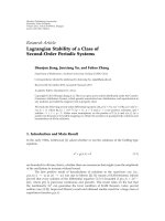
Figure 5 depicts the boundary conditions of switching a
RRC as a function of γ
1
and γ
2
as given by (23)and(25)for
fractional frequency reuse and macro-diversity, respectively.
As stated in Proposition 3,agreaterγ
2
is needed for an
upward switch when λ is higher.
Thus far, we have assumed that the average capacity of
the interior users in a neighboring cell is available. When
this information is unavailable in the network, or each user
(instead of an classifier or an admission controller) indepen-
dently wants to decide the RRC switch without network-
level information, we can obtain approximate conditions
assuming λ
= 1(i.e.,C
1
= C
2
). Then, the conditions of (14)
and (20) are simply expressed by
C
1,2
(
k
)
− 2C
1
(
k
)
≥ 0, C
1,2
(
k
)
− 2C
1
(
k
)
< 0.
(26)
Specifically, in the case of macro-diversity, the boundary
condition in (25)isgivenby
γ
2
=
1+4γ
1
1/2
− 1
2
,
(27)
−15
−10
−5
0
5
10
15
−15 −10 −50 51015
γ
1
(dB)
γ
2
(dB)
λ = 0.5
λ
= 1
λ
= 2
MD
FFR
Lower-level RRM
Lower-level RRM
Upper-level RRM
Figure 5: Boundary conditions of switching a RRC.
which provides an insight for designing H Add Threshold
and H
Delete Threshold for macrodiversity hand-off procedure
defined in the IEEE 802.16e standard [18]. The IEEE 802.16e
standard introduces a macro diversity hand-off procedure
where a mobile user is able to transmit or receive unicast
messages and traffic from multiple BSs at the same time
interval. According to [18], when the long-term SINR of
a serving BS is less than H
Delete Threshold, the mobile
station shall send MOB
MSHO-REQ to require dropping
this serving BS from the diversity set, and when the long-
term SINR of a neighboring BS is higher than H
Add
Threshold, the mobile station shall send MOB
MSHO-REQ
to require adding this neighbor BS to the diversity set.
6. Implementation Issue
The overhead of RRC switch is the exchange of signaling
messages for switch request and response between two
RRCs. If the algorithms are triggered more frequently,
the classification will probably be more accurate, but the
overhead will be higher. The overhead is related to how
frequently C
1
(k), C
1,2
(k), C
1
,andC
2
in (14)change.
One factor that affects a user’s capacity, that is, C
1
(k)and
C
1,2
(k)aswellasC
1
and C
2
, is user mobility, because the
capacity of fast-moving users may vary in a small-time scale.
If they are able to compute γ
1
and γ
2
viaalong-termaverage,
they will not suffer from frequent RRC switch. An alternative
is to make fast-moving users always be managed by the upper
RRC regardless of whether they are classified as cell-interior
or cell-edge users.
Meanwhile, a factor that affects
C
1
or C
2
is addition or
deletion of a user in the cell, which may trigger switching of
other users. This is explained by simultaneous switching. In
case more than two users trigger switching simultaneously,
the conditions of a permissible switching is also derived.
10 EURASIP Journal on Wireless Communications and Networking
Table 1: Parameters for simulation [19].
Channel bandwidth 5 MHz No. of subchannels 8
Carrier frequency 2.3 GHz TX power at BSs 43 dBm
Cell radius 1 Km Path loss exp. 4
Shadowing var. 8 dB Max. Doppler vel. 3 Km/hr
Number of users 30 T
min
(i) 150 Kbps
Simulation time 60 seconds No. of simulations 1000
We refer to the set of all users for which reclassification is
permissible as the permissible set. We can adopt a sequential
approach where the user from the permissible set which
offers the highest throughput gain upon switching is selected
and reclassified. The permissible set is then recomputed
before switching the next selected user. In each step, the
procedure is the same as the reclassification algorithm stated
earlier. This approach will converge to a state for which the
permissible set is empty, because at each step, the system
throughput strictly increases upon switching.
7. Simulation Results
We evaluated the performance in an OFDMA-based wire-
less network by simulation experiments, emulating mobile
WiMAX systems with parameters listed in Table 1.Wecon-
sider a single omnidirectional antenna at each transmitter
and each receiver. In our simulator, users are uniformly
distributed in a hexagonal cell and BSs of 6 first-tier and 12
second-tier neighboring cells generate intercell interference
to those users. Our channel model follows path loss with
an exponent of 4, Gaussian shadowing with zero mean and
variance of 8 dB, and Rayleigh fading. We use the Jakes’
model [20] to generate frequency-selective Rayleigh fading
followed by the Doppler effect with the maximum velocity
of 3 Km/hr. To serve cell-interior users, BSs either adopt
a round-robin (RR) scheduling algorithm or a multichan-
nel proportional fair (PF) scheduling algorithm [21] that
guarantees minimum throughput (150 Kbps for all users in
our setting) [10]. It is assumed that the channel coefficients
are perfectly known at the BS and the data rate is then
determined by the Shannon capacity. In our simulation, each
user measures the two strongest γ’s from their neighboring
BSs, and the serving BS is able to coordinate with one or
two of those neighboring BSs. The cell performance was
computed during the simulation time of 60 seconds, after
each user’s RRC had been completely determined according
to our algorithm.
Our simulation results show that users are appropriately
classified into cell-edge and cell-interior types by our algo-
rithms. We confirmed that (i) the first cases in Propositions
1 and 2 are generally observed, (ii) FFR and macro-diversity
(MD) increase cell-edge throughput by up to 15% when
λ
= 1 without a loss in system throughput, and (iii) more
users switch to the cell-edge type when the neighboring cell
is lightly loaded.
Figure 6 plots the ratio of edge users in the cell. The cell-
edge users are now divided into the users coordinated by
0
0.03
0.06
0.09
0.12
0.50.75 1 1.25 1.5
λ
Ratio of cell-edge users
PF + FFR-2
PF + FFR-3
PF + MD-2
PF + MD-3
Figure 6: The ratio of cell-edge users for FFR-2, FFR-3, MD-2, and
MD-3.
−3
−2
−1
0
1
2
3
4
5
6
7
8
−3 −2 −1012345678
γ
1
(dB)
γ
2
(dB)
Lower-level RRM (BS2)
Upper-level RRM
(macro diversity)
Lower-level RRM (BS1)
Figure 7: Distribution of cell-edge users’ γ
1
and γ
2
when macro-
diversity is used and
C
1
= C
2
.
two BSs (FFR-2 and MD-2) and users coordinated by three
BSs (FFR-3 and MD-3). Here, PF scheduling for cell-interior
users is only plotted, because RR scheduling has the same
tendency. In any cases, users can take advantage of FFR-2 or
MD-2 more than FFR-3 or MD-3. Interestingly, the ratio of
users supported by MD-3 is very small unlike MD-2, which
means that macro-diversity by three BSs is not so beneficial
in enhancing the throughput of cell-edge users.
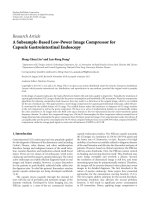
Figure 7 shows the distribution of cell-edge users’ γ
1
and
γ
2
in the case of Figure 5, when macro-diversity by at most
two BSs is employed and
C
1
= C
2
. The black area represents
γ
1
and γ
2
of those users by simulation results and two lines
represent the threshold given by (14). In this experiment,
the other cases except the first one in Propositions 1 and
2 are rarely observed; for instance, the ratio of such cases
EURASIP Journal on Wireless Communications and Networking 11
−1000
−500
0
500
1000
−1000 −500 0 500 1000
X (m)
Y (m)
Figure 8: An example: the region of cell-edge users in a cell.
Proposed (PF + FFR)
Proposed (PF + MD)
Relaxed (PF + MD)
Fixed (PF + MD, 7dB)
Fixed (PF + MD, 3dB)
Cell-edge
System
Throughput (Mbps)
012345
Figure 9: Comparison of cell-edge users’ average throughput and
system throughput in various mechanisms.
is only 0.5% among all users at λ = 0.2 and it approaches
zero as λ increases above 0.2. Therefore, as expected, the first
cases can be regarded as the simplified solution in general.
Furthermore, Figure 8 shows the possible location of cell-
edge users in a hexagonal cell, when a user type is classified
according to (26).
The average cell-edge throughput and system throughput
(i.e., cell throughput in this simulation) are presented in
Figure 9 when λ
= 1. Both “PF + FFR” and “PF + MD”
represent the cases where cell-interior users are supported
by the PF scheduling and cell-edge users are supported by
FFR or MD. The proposed algorithm shows better cell-edge
throughput, compared to the relaxed switching (“Relaxed”)
mentioned in Remark 2. Also, our algorithm is compared to
a simple mechanism (represented by “Fixed”) where RRC
−40 −30 −20 −100 102030
Proposed (PF + FFR)
Proposed (PF + MD)
Relaxed (PF + MD)
Improvement (%)
Fixed (PF + MD, 3 dB)
Fixed (PF + MD, 7 dB)
−27.3%
−35.3%
4.2%
14.3%
13%
Figure 10: Throughput improvement of upper-managed users
compared to the case with no upper RRC.
3.6
3.8
4
4.2
4.4
4.6
0.50.75 1 1.25 1.51.75 2
λ
Throughput (Mbps)
PF + MD
PF + FFR
RR + MD
RR + FFR
Figure 11: Throughput comparison between MD and FFD as a
function of λ.
switch is determined by a fixed threshold, γ
1
− γ
2
(3 dB or
7dB).Here,γ
2
is given by the neighboring BS that interferes
most dominantly.
In the case of Figure 9, we obtained throughput improve-
ment of cell-edge users, as shown in Figure 10.Compared
to the case of no upper RRC, the proposed one improves
cell-edge throughput by 13.0% and 14.3% for FFR and
MD, respectively, without a loss in system throughput,
while the relaxed case improves it only by 4.2%. But the
“Fixed” algorithm degrades those users’ throughput. In
summary, the proposed algorithm achieves the best cell-
edge throughput without losing system throughput. We omit
“PF + FFR” for the fixed and relaxed switching because
it results in a slightly inferior cell-edge performance to
“PF + MD”.
12 EURASIP Journal on Wireless Communications and Networking
0
0.1
0.2
0.3
0.4
0.5
0.6
0.50.75 1 1.25 1.5
λ
β
PF + FFR
PF + MD
RR + FFR
RR + MD
Figure 12: β versus λ.
Figure 11 shows the throughput comparison between
FFR and MD as a function of λ, when λ is averaged over
six neighboring cells. Throughput improvement decreases as
λ increases, because less users are allowed to switch to the
upper RRC. When PF is used for cell-interior users, there
is little difference between FFR and MD. In contrast, when
RR scheduling is employed for cell-interior users (see “RR +
FFR” and “RR + MD”), it is shown that MD is better than
FFR in improving the overall throughput.
The effect of λ is demonstrated in Figure 12 that plots
β as a function of λ.Here,β also includes the fraction of
resource allocated to cell-edge users who are located in six
neighboring cells. As discussed in Proposition 3, users are less
likely to switch to the upper RRC as λ increases. To obtain
this result, we imposed no upper limit on β (i.e., β
max
= 1).
When RR scheduling is employed for cell-interior users, they
do not take advantage of opportunistic scheduling, and thus
it drives more users to switch to the upper RRC. Therefore,
β in case of RR scheduling is much greater than that of PF
scheduling.
8. Conclusion
We have proposed a new RRM framework for wide-
area wireless data networks that manages radio resources
of cell-interior and cell-edge users separately. We believe
that our framework can be employed with many recent
approaches that require network coordination to improve
cell-edge throughput, including fractional frequency reuse,
macro-diversity, and various other forms of network MIMO
techniques applicable to cell-edge users, although we focused
on fractional frequency reuse and macro-diversity in this
work. The work presented in this paper has been limited
to downlink data transmission; RRM schemes for uplink in
conjunction with downlink would be one avenue for future
work.
Appendices
A. Proof of Proposition 1
In the case of (i), the RRC switch is possible if an α
(k) exists
such that
α
(
k
)
C
1
(
k
)
C
1,2
(
k
)
≤ α
(
k
)
≤ α
(
k
)
C
1
− C
1
(
k
)
C
1
+ C
2
− C
1,2
(
k
)
,
(A.1)
which is obtained from (10)and(11). The upper bound must
be greater than the lower bound, which results in (14). The
objective is maximized by the minimal value; that is, α
(k) =
α(k)C
1
(k)/C
1,2
(k). The proofs of the other cases are omitted
because they follow along similar lines.
B.ProofofProposition3
For brevity, we only prove the case of upward switching. In
the case of fractional frequency reuse, (23)isequivalentto
λ<
log
1+γ
1
log
1+γ
1
/
γ
2
+1
−
1 f
γ
2
(B.2)
In the case of macro-diversity, (25)canberewrittenas
λ<
1
1 − log
1+γ
2
/ log
1+γ
1
+ γ
2
− 1 g
γ
2
.
(B.3)
It is easily proved that for a fixed γ
1
, f (γ
2
)andg(γ
2
)are
monotonically increasing functions of γ
2
. Therefore, as the
average capacity of a neighboring cell 2 increases (i.e., as λ
increases), an increasing value of γ
2
is required.
Acknowledgment
Part of this paper was presented in the Proceedings of
QSHINE 2009. This research was partly supported by the
MKE (the Ministry of Knowledge Economy), Korea, under
the ITRC (Information Technology Research Center) sup-
port program supervised by the NIPA (National IT Industry
Promotion Agency) (NIPA-2009-C1090-0902-0003).
References
[1] T P. Chu and S. S. Rappaport, “Overlapping coverage with
reuse partitioning in cellular communication systems,” IEEE
Transactions on Vehicular Technology, vol. 46, no. 1, pp. 41–54,
1997.
[2] G. Li and H. Liu, “Downlink radio resource allocation for
multi-cell OFDMA system,” IEEE Transactions on Wireless
Communications, vol. 5, no. 12, pp. 3451–3459, 2006.
[3] S E. Elayoubi, O. Ben Haddada, and B. Fouresti
´
e, “Perfor-
mance evaluation of frequency planning schemes in OFDMA-
based networks,” IEEE Transactions on Wireless Communica-
tions, vol. 7, no. 5, pp. 1623–1633, 2008.
[4] Qualcomm R1-050896, “Description and simulations of inter-
ference management technique for OFDMA based E-UTRA
downlink evaluation,” 3GPP TSG-RAN WG1 #42, August
2005.
[5] S. Kim, J. Kim, D. Lim, B. C. Ihm, and H. Cho, “Interference
mitigation using FFR and multi-cell MIMO in downlink,”
IEEE C802.16m-08/783r1, July 2008.
EURASIP Journal on Wireless Communications and Networking 13
[6] R. C. Bernhardt, “Macroscopic diversity in frequency reuse
radio systems,” IEEE Journal on Selected Areas in Communi-
cations, vol. 5, no. 5, pp. 862–870, 1987.
[7] M. K. Karakayali, G. J. Foschini, and R. A. Valenzuela, “Net-
work coordination for spectrally efficient communications in
cellular systems,” IEEE Wireless Communications, vol. 13, no.
4, pp. 56–61, 2006.
[8] G. J. Foschini, K. Karakayali, and R. A. Valenzuela, “Coor-
dinating multiple antenna cellular networks to achieve enor-
mous spectral efficiency,” IEE Proceedings, vol. 153, no. 4, pp.
548–555, 2006.
[9]X.Liu,E.K.P.Chong,andN.B.Shroff, “Opportunistic
transmission scheduling with resource-sharing constraints
in wireless networks,” IEEE Journal on Selected Areas in
Communications, vol. 19, no. 10, pp. 2053–2064, 2001.
[10] M. Andrews, L. Qian, and A. Stolyar, “Optimal utility
based multi-user throughput allocation subject to throughput
constraints,” in Proceedings of the Annual Joint Conference of
the IEEE Computer and Communications Societies (INFOCOM
’05), vol. 4, pp. 2415–2424, Miami, Fla, USA, March 2005.
[11] A. Jalali, R. Padovani, and R. Pankaj, “Data throughput
of CDMA-HDR a high efficiency-high data rate personal
communication wireless system,” in Proceedings of the IEEE
Vehicular Technology Conference (VTC ’00), vol. 3, pp. 1854–
1858, Tokyo, Japan, May 2000.
[12] T. Yoo, N. Jindal, and A. Goldsmith, “Multi-antenna downlink
channels with limited feedback and user selection,” IEEE
Journal on Selected Areas in Communications,vol.25,no.7,pp.
1478–1491, 2007.
[13] 3GPP2 C.S0024-B v2.0, “cdma2000 High Rate Packet Data Air
Interface Specification,” April 2007.
[14] 3GPP TR 25.858 V5.0.0, “High Speed Downlink Packet Access:
Physical Layer Aspects(Release5),” March 2002.
[15] WiMAX Forum, “WiMAX Forum Network Architecture,” ver.
1.2, January 2008.
[16] S. M. Alamouti, “A simple transmit diversity technique for
wireless communications,” IEEE Journal on Selected Areas in
Communications, vol. 16, no. 8, pp. 1451–1458, 1998.
[17] V. Tarokh, H. Jafarkhani, and A. R. Calderbank, “Space-time
block codes from orthogonal designs,” IEEE Transactions on
Information Theory, vol. 45, no. 5, pp. 1456–1467, 1999.
[18] IEEE 802.16e-2005, “Part 16: Air Interface for Fixed and
Mobile Broadband Wireless Access Systems Amendment,”
February 2006.
[19] WiMAX forum, “Mobile WiMAX—Part I: A Technical
Overview and Performance Evaluation,” August 2006.
[20] W. C. Jakes, MicrowaveMobileCommunications, John Wiley &
Sons, New York, NY, USA, 1975.
[21] H. Kim and Y. Han, “A proportional fair scheduling for
multicarrier transmission systems,” IEEE Communications
Letters, vol. 9, no. 3, pp. 210–212, 2005.