Báo cáo hóa học: " Research Article Energy-Efficient Reservation-Based Medium Access Control Protocol for Wireless Sensor Networks" doc
Bạn đang xem bản rút gọn của tài liệu. Xem và tải ngay bản đầy đủ của tài liệu tại đây (2.42 MB, 22 trang )
Hindawi Publishing Corporation
EURASIP Journal on Wireless Communications and Networking
Volume 2010, Article ID 878412, 22 pages
doi:10.1155/2010/878412
Research Article
Energy-Efficient Reservation-Based Medium Access Control
Protocol for Wireless Sensor Networks
Mikko Kohvakka, Jukka Suhonen, Timo D. H
¨
am
¨
al
¨
ainen, and Marko H
¨
annik
¨
ainen
Department of Computer Systems, Tampere University of Technology, 33720 Tampere, Finland
Correspondence should be addressed to Jukka Suhonen, jukka.suhonen@tut.fi
Received 13 April 2010; Accepted 16 August 2010
Academic Editor: Sudip Misra
Copyright © 2010 Mikko Kohvakka et al. This is an open access article distributed under the Creative Commons Attribution
License, w hich permits unrestricted use, distribution, and reproduction i n any medium, provided the original work is properly
cited.
In Wireless Sensor Networks (WSNs), a robust and energy-efficient Medium Access Control (MAC) protocol is required for high
energy efficiency in harsh operating conditions, where node and link failures are common. This paper presents the design of
a novel MAC protocol for low-power WSNs. The developed MAC protocol minimizes the energy overhead of idle time and
collisions by strict frame synchronization and slot reservation. It combines a dynamic bandwidth adjustment mechanism, multi-
cluster-tree network topology, and a network channel allowing rapid and low-energy neighbor discoveries. The protocol achieves
high scalability by employing frequency and time division between clusters. Performance analysis shows that the MAC protocol
outperforms current state-of-the-art protocols in energy efficiency, and the energy overhead compared to an ideal MAC protocol
is only 2.85% to 27.1%. The high energy efficiency is achieved in both leaf and router nodes. The models and the feasibility of the
protocol were verified by simulations and with a full-scale prototype implementation.
1. Introduction
Wireless Sensor Network (WSN) is an emerging technology,
which combines distributed sensing and computing with
wireless communication. WSN may consist of thousands of
self-configuring and self-healing nodes, which automatically
form a multihop network topology [1, 2]. Data is routed to
one or more sink nodes, which may operate as user interfaces
or gateways to other networks. WSNs have a vast number
of potential applications [3], for example monitoring of
remote or hostile geographical regions, tracking of animals
and objects, and surveillance [1, 4–7].
This paper focuses on very low-energy WSNs, where
small, cheap, and even disposable nodes should operate
up to years with small batteries, while actively perform ing
measurements. To reach the energy, cost, and size budget,
WSN nodes operate with very limited communication and
computation resources. Although the advances in Radio
Frequency (RF) circuits have been remarkable in recent
years, a radio transceiver is still the most power-consuming
component of a WSN node. The power consumption of
current radios is nearly the same in the transmission and
reception modes. Low power consumption is achieved only
in the sleep mode, in which the ra dio circuitry is completely
switched off. To be able to reach the energy budget, radio
should be activated only when transmitting or receiving a
packet that is vital for the node operation.
This paper focuses on a Medium Access Control (MAC)
protocol design for presenting a solution for the energy
consumption challenge. The MAC protocol manages radio
transmissions and receptions on a shared wireless medium.
Thus, MAC has a very high effect on network performance
and energy consumption. The design objectives of low-
energy WSN MAC protocols differ completely from the
MAC protocols of traditional wireless computer networks,
such as IEEE 802.11 wireless LAN, as presented in Table 1.
While the latter pursue to maximize achieved throughput,
low-energy WSN MAC protocols are aiming to maximize
energy-efficiency. Other key design objectives are adaptivity
for maintaining the robust and energy-efficient operation in
a dynamic environment, where the network size, topology,
and radio propagation conditions vary, and scalability for
providing high energy efficiency and performance inde-
pendently on a network size and density. WSN MAC
2 EURASIP Journal on Wireless Communications and Networking
Table 1: Opposite MAC requirements for wireless computer
networks and low-energy WSNs.
Criticality for MAC protocols
Requirement
Wireless
computer
networks
Low-energy
WSNs
Energy efficiency
Lowest Highest
Adaptivity
Low High
Scalability
Moderate High
Fairness
Moderate Moderate
Latency
High Low
Throughput
Highest Lowest
protocol should also ensure fairness, such that sinks receive
information from all sources equally. In addition, a protocol
should provide adequate throughput and latency for a given
application. Sufficient throughput for WSN applications may
be around few kbits/s [8], while a source-to-sink latency may
be even tens of seconds. Yet, one of the most important
design requirements is practical feasibility, as the available
computation and memory resources are very constrained.
To be able to reach adequate energy efficiency, a low-
energy MAC protocol must minimize the following [5]:
(i) unnecessary listening of a Radio Frequency (RF)
channel (idle listening),
(ii) frame collisions,
(iii) overhearing of frames intended to other nodes, and
(iv) network signaling trafficoverhead.
In practice, the highest energy efficiency is achieved,
when a source and a destination node are activated and tuned
on a correct RF channel simultaneously for a frame exchange,
while other nodes remain in sleep mode. This is very difficult
in large and resource constrained WSNs having dynamically
changing network topology.
In this paper, we present a survey of existing low-energy
MAC protocols and standards for WSNs. It is shown that the
existing MAC protocols lack the performance to adequately
fulfill the energy efficiency and adaptivity requirements of
low-energy WSNs. T his motivates the design of a new low-
energy MAC protocol called TUTWSN MAC. First, the
energy overhead in existing MAC protocols is modeled and
analyzed, and then a new protocol is designed by eliminating
the most essential causes of the overhead in each radio
transaction. The key principles for maximizing the energy
efficiency are a collision-free slot reservation-based channel
access, and a strict synchronization of transmissions and
receptions. For further improving the energy efficiency, a
dynamic bandwidth adjustment mechanism, and a multi-
cluster-tree network topology are designed. The performance
of the designed protocol is verified and compared to existing
protocols and standards by performance modeling and
energy analysis. Finally, the performance and feasibility of
the design is validated by simulations and experimental
measurements in real WSN implementations.
This paper is organized as follows. Section 2 presents the
essential low-power MAC protocols proposed for WSNs. The
energy overhead in wireless channel access is analyzed in
Section 3. Section 4 presents the design and implementation
of TUTWSN MAC. The performance of TUTWSN MAC is
analyzed and compared with related proposals in Section 5.
Performance simulations are presented in Section 6.Experi-
mental power consumption measurements are carried out in
Section 7. Finally, the paper is concluded in Section 8.
2. Related Research
MAC protocols have been typically categorized into con-
tention and contention-free protocols. In contention proto-
cols, nodes compete for a shared channel, while trying to
avoid frame collisions, for example by using car rier sens-
ing [9], and Request-To-Send-(RTS-) Clear-To-Send (CTS)
handshaking [10, 11]. Examples of contention protocols are
Carrier Sense Multiple Access (CSMA) [9] and MACA [10].
In contention-free protocols, nodes get unique time slots,
frequency channels, or spreading codes for transmissions
eliminating collisions. This simplifies the individual trans-
missions, but the required bandwidth must be reserved prior
to data transmissions increasing signaling traffic. Examples
of contention-free protocols are Time Division Multiple
Access (TDMA) [12], Frequency Division Multiple Access
(FDMA) [13], and Code Division Multiple Access (CDMA)
[14].
The contention protocols are more flexible than
contention-free protocols, as the bandwidth is divided
among nodes on-demand basis. However, contention proto-
cols suffer from collisions and high idle listening. Still, while
the contention-free protocols theoretically optimize the
channel usage, adjusting the correct amount of reservations
is challenging and generally possible only for static networks.
Even then, monitored events may generate traffic bursts,
thus causing temporarily high bandwidth usage that cannot
be served with rigid reservations. Therefore, in this paper,
we concentrate on MAC protocols that support dynamic
operation and variable trafficloads.
Due to the fundamental limitations of current low-power
transceivers, the energy efficiency of the conventional MAC
approaches is not adequate for the lowest energy WSN
applications as such. Further energy saving is achieved by
duty cycling: time is divided into a short active period and
a long sleep period, which are repeated consecutively. These
low duty-cycle protocols can be divided into two categories:
unsynchronized and synchronized protocols, according to
the synchronization of data exchanges.
2.1. Unsynchronized Low Duty-Cycle MAC Protocols. Unsyn-
chronized low duty-cycle MAC protocols are based on a Low
Power Listening (LPL) mechanism, where nodes poll channel
asynchronously to test for possible traffic. Transmissions are
preceded with a preamble that is longer than the channel-
polling interval. Hence, the preamble part acts like a wakeup
signal. If a busy channel is detected, nodes begin to listen
to the channel until a data packet is received or a time-
out occurs. Berkeley Media Access Control (B-MAC) [15]
EURASIP Journal on Wireless Communications and Networking 3
is a simple LPL protocol, which utilizes CSMA for collision
avoidance. The energy efficiency of B-MAC is significantly
limited by the transmission and reception energ y costs
caused by the long preamble. In addition, the overhearing
of frames intended to other nodes and the idle listening
caused by the frequent channel sampling reduces its energy
efficiency.
Zebra-MAC (Z-MAC) [16]operatesaboveB-MACbut
utilizes TDMA for managing congestion. As a principle, each
node owns a slot during which a smaller CSMA contention
window is used compared to other nodes. Thus, the slot
owner always has the best possibility to access the channel.
Consequently, other nodes can steal the slot, if the slot owner
does not have d ata to transmit. Under low contention, Z-
MAC behaves like CSMA and under high contention more
like TDMA. The utilization of slots improves the fairness
and throughput of B-MAC. Yet, the improvement on energy-
efficiency is only limited.
There are numerous variations of B-MAC targeting at
the reduction of the preamble energy. SpeckMAC-Backoff
(SpeckMAC-B) [17] replaces the long preamble with numer-
ous short wakeup packets containing a destination address
and an exact time to the actual data transmission. Thus,
nodes may return to sleep mode after receiving one wakeup
packet. SpeckMAC-Data (SpeckMAC-D) [17] replaces the
long preamble with consecutive data packets reducing the
required channel reception time. In X-MAC [18],asender
transmits multiple short preambles with the address of the
intended receiver. Upon receiving a short preamble, the
desired destination node sends an ACK between the short
preambles. Other nodes can enter early a sleep mode for
reducing overhearing. After receiving the ACK, the source
node begins the transmission of a data frame. Disadvantages
of these protocols are the transmission cost of a preamble and
idle listening caused by CSMA mechanism, channel polling,
overhearing and radio startup transients.
Therearetwoprotocols,whichreducepreambleenergy
by combining LPL with synchronization. Wireless Sensor
MAC (WiseMAC) [19] utilizes ALOHA for transmissions.
A network consists of an access point and numerous sensor
nodes in a star topology. The access point learns the
sampling schedules of each sensor node and starts preamble
transmission just prior to the channel sampling moment
of a desired destination node. Major disadvantages of the
protocol are very limited coverage and connectivity of the
network due to the star topology. Scheduled Channel Polling
MAC (SCP-MAC) [20] is a synchronized variation of B-
MAC, which operates in a peer-to-peer network by synchro-
nizing the channel polling schedules of all neighbors. Hence,
only a short preamble is required to reach all neighbors.
The energy consumption of preambles is reduced over one
order of magnitude compared to B-MAC. Synchronization
is performed by transmitting periodically synchronization
(SYNC) packets containing the schedule information, or
piggybacking the information in data packets. SCP-MAC
is currently the most energy-efficient unsynchronized low
duty-cycle protocol. Still, idle listening in contention win-
dows, collisions, channel polling, frequent radio startup
transients, and overhearing reduces its energy efficiency.
Unsynchronized protocols are relatively simple and
robust, and require small amount of memory compared to
synchronized protocols. Frequent channel polling increases
radio startup transients causing wasted energy. A general
drawback is rather high overhearing, since each node must
receive at least the beginning of each frame transmitted
within radio range. Thus, they suit best for relatively
simple WSNs utilizing very low data rates. Unsynchronized
protocols tolerate dynamics in networks, but their energy-
efficiency is limited by the channel sampling and collision
avoidance mechanism.
2.2. Synchronized Low Duty-Cycle MAC Protocols. Synchro-
nized low duty-cycle MAC protocols utilize scheduling to
ensure that listeners and transmitters have a regular, short
active per iod in which to rendezvous. Due to a synchronized
operation, nodes know the exact moments of active periods
in advance, which eliminate the need of long preambles. As
a global synchronization is very difficult in large networks
[21], active periods occur typically asynchronously. Nodes
signal their schedules by transmitting periodically SYCN
frames. By receiving the SYNC frames, nodes maintain
local synchronization with one or more neighboring nodes.
Synchronization is typically obtained by a network scan,
during which a node listens to an RF channel until SYNC
frames from neighbors are received.
A Sensor-MAC (S-MAC) [22] is one of the first synchro-
nized low duty-cycle MAC proposals. The protocol utilizes
a fixed active period length and an adjustable, network
specific wakeup period. Neighboring nodes may coordinate
their active per iods to occur simultaneously to form virtual
clusters. An active period is divided into SYNC, RTS, and
CTS phases. In SYNC phase, a node receives SYNC frames
from its neighbors. In RTS phase, the neighboring nodes
transmit RTS frames, from which a node selects a desired
source node, and transmits a CTS frame. The CTS phase is
followed by frame exchanges with the selected node until the
end of the wakeup period. All frames are transmitted using
CSMA. The energy nefficiency of S-MAC is reduced by long
SYNC and RTS phases, and fixed active period length causing
idle listening. In addition, the fixed duty cycle causes poor
adaptation to changing traffic conditions. A Timeout-MAC
(T-MAC) [23] protocol is a variation of the S-MAC, which
utilizes a short listening w indow after the CTS phase. Node
is in active period as long as activity occurs. Thus, the length
of the active period is adjusted according to traffic. Still, the
energy efficiency is limited by the idle listening in SYNC and
RTS phases.
The IEEE 802.15.4 Low-Rate Wireless Personal Area
Network [24] is a multipurpose standard specifying PHY
layer and MAC sublayer. The ZigBee Alliance [25] builds
on this foundation by providing the network layer and the
framework for the application layer. IEEE 802.15.4 provides
a synchronized low duty-cycle operation by optional beacon-
ing mode, inactive period, and cluster-tree network topology.
A network is formed around a PAN coordinator that is the
central manager. Cluster heads (coordinators) transmit a
SYNC frame (beacon) at the beginning of their active p eriods
(superframes). Then, they listen to the channel for incoming
4 EURASIP Journal on Wireless Communications and Networking
data until the end of the superframe in a Contention Access
Period (CAP). Each node maintains synchronization with a
parent coordinator by receiving its beacons and transmitting
data in CAP on-demand basis. Leaf nodes (devices) do not
transmit beacons or route data resulting in very low energy
consumption.
Data exchanges in CAP are performed using a slotted
variation of CSMA. Energy consumption is reduced by
spending backoff times in a sleep mode. The number of
collisions is minimized by performing carrier sensing twice.
IEEE 802.15.4 supports also a Contention-Free Period (CFP)
consisting of dedicated time slots for individual nodes. Yet,
CFP slots can be only used for direct communication with
a PAN coordinator. The cluster-tree type IEEE 802.15.4
network can provide comparably good energy efficiency in
static and sparse networks. A major disadvantage is that
coordinators must be active entire CAP causing significant
idle listening. Since node addressing and routing schemes
are based on a highly static tree network structure, achieved
performance degrades rapidly in a dynamic network [26]. In
addition, the hidden node problem reduces performance in
dense networks, since any handshaking prior to a transmis-
sion is not used.
Several variations of TDMA are also proposed for low-
energy WSN. At the best, they can provide energy-efficient,
fair, and collision-free channel access. Low-Energy Adaptive
Clustering Hierarchy (LEACH) [27] protocol uses TDMA
with clustered network topology. LEACH utilizes a single
base station, w ith which all cluster heads employ only direct
communications. Intercluster interferences are managed by
CDMA. In large networks, the energy efficiency of cluster
heads is limited due to the direct communication with
a base station. However, cluster members operate quite
energy efficiently. For increasing network lifetime, LEACH
proposes to compress data in cluster heads and to rotate
of cluster heads. A drawback is that LEACH does not
support dynamically changing network size. In addition, the
assumption that all nodes can reach the base station with
the maximum transmission power level strictly limits the
coverage area and operation environment. These problems
are addressed in Power Aware Clustered TDMA (PACT) [28]
protocol. PACT is a variation of LEACH, which performs
data relaying between clusters by intercluster gateway nodes,
similar to [29]. Disadvantages of PACT are relatively high
control traffic overhead and idle listening in larger networks.
Relatively complex data slot scheduling algorithm perfor ms
well in static networks, but lacks support for dynamic
network.
Self-Organizing Medium Access Control for Sensor
Networks (SMACS) [30] protocol assigns a locally unique
contention-free slot for each link. Neighbor discovery is
performed at semiregular inter vals by broadcasting invi-
tation messages on a common signaling channel. Then,
the channel is received for possible responses and other
invitation messages. According to invitation messages, each
pair of nodes mutually agrees a periodic time and frequency
slot for data exchanges. A major disadvantage is the energy
consumption of a neighbor discovery requiring a long-term
radio reception. This severely limits energy efficiency and
adaptivity in dynamic networks, where link lifetimes are
short.
Traffic-Adaptive Medium Access (TRAMA) [31]isa
scalable TDMA protocol designed for multihop networks.
By using a distributed algorithm, only one transmitter
per two-hop neighborhood is selected allowing collision-
free data reception and peer-to-peer connectivity. TRAMA
can command a set of neighbors to receive a given data
frame providing efficient unicast, multicast, and broadcast
transmissions. Nodes that are not selected to transmit or
receive at a particular time slot go to a sleep mode. Neighbor
information is updated during periodic and relatively long-
term random access periods. TRAMA can provide collision-
free medium access in a static network. Energy efficiency is
reduced by signaling traffic overhead and the random access
period requiring a long-term radio reception. Hence, the
energy efficiency and performance decrease significantly in
dynamic networks.
In current synchronized low duty-cycle protocols, the
major advantage is that a sender knows a receiver’s wakeup
time a priori and thus tr ansmits efficiently. In dynamic
networks, synchronized links are short-lived and new neigh-
bors need to be searched frequently, w hich increases energy
consumption. In contention protocols, a major disadvantage
is the energy cost of receiving an entire active period [15].
Contention-free protocols suffer from a poor performance
in dynamic network topology. However, synchronized pro-
tocols typically have better energy efficiency than unsynchro-
nized approaches in stationary networks.
Due to the energy efficiency, our work utilizes the
synchronized low duty-cycle approach. In contrast to the
above schemes, our work can minimize the idle listening
of all nodes in a multihop network, and provide energy-
efficient operation in dynamic networks. We will present
energy-efficient solutions for channel access mechanism,
dynamic bandwidth management, network topology, and
RF channel utilization. The presented protocol uses hybrid
approach in channel access. A contention-free method
prevents collisions and minimizes idle listening, while a
contention-based method supports varying trafficloads.
Thus, although the protocol design itself is TDMA-based, it
supports network dynamics and is therefore compared to the
related contention-based protocols.
3. Energy Overhead in Channel Access
MAC protocol can be divided into channel access and
networking mechanisms. The channel access mechanism
defines radio utilization for maintaining synchronization
and exchanging frames between nodes. The networking
mechanisms perform network self-configuration and neigh-
bor discovery operations.
Until now, low-energy channel access mechanisms have
reduced energy consumption by focusing on the minimiza-
tion of long-term idle listening, overhearing, and the active
period length. Only a small research effort has been made
to the minimization of the energy overhead in each radio
operation. For finding out the most essential causes of energy
overhead, a simple energy analysis of a CSMA channel access
EURASIP Journal on Wireless Communications and Networking 5
is presented. CSMA can be considered a typical channel
access mechanism in WSNs, and it is used for example in
IEEE 802.15.4 [24], S-MAC [22], T-MAC [23], SCP-MAC
[20], and X-MAC [18]. To be able to focus purely on the data
exchange between two nodes, an analyzed network contains
only a source and a destination node.
At the beginning of a channel access period, a destination
node activates its receiver and begins receiving the channel
for possible incoming frames. The transition time from the
low-energy state to the reception state is denoted as t
ST
.
Prior to a data frame transmission, the source node waits a
random backoff time t
BOT
, activates its receiver, and performs
a carrier sensing t
CCA
. For improving energy efficiency, a
blind backoff is assumed, where a source spends t
BOT
in sleep
mode. If the channel is idle, the source turns the receiver off,
activates its transmitter, and transmits a data frame t
DA T A
.
The energy of inactivating the radio is negligible and it can
be ignored. When the data frame has been received, the
destination node turns off the receiver, checks the correctness
of the data t
AW
, activates a transmitter, and transmits ACK.
Since the wait time t
AW
prior to the reception of ACK is
not predetermined, and depends on the frame content and
data processing performance, the source node needs to be in
reception mode entire t
AW
.
The consumed energy is divided into an effective energy
comprising data and ACK exchange energies, and overhead
energy consisting of radio startup, backoff,andACKwait
energies. Next, models for these energies are determined.
The presented frame exchange procedure consists of
three transmitter startup and two receiver startup transients
(t
ST
) during which power consumption equals to a transmit-
ting power (P
TX
) and a receiving power (P
RX
), respectively.
Hence, the total startup energy (E
ST
)ofaframeexchangeis
E
ST
= t
ST
(
2P
TX
+3P
RX
)
. (1)
Although the source node may sleep during the backoff
delay, the destination node needs to be in reception mode. An
average idle listening time consists of a half of a contention
window length (t
CW
) and a carrier sensing time (t
CCA
).
Hence, the backoff energy consumption (E
BO
)is
E
BO
=
t
CW
2
+ t
CCA
P
RX
. (2)
ACK wait energy consumption (E
AW
) caused by an
average ACK wait delay (t
AW
)is
E
AW
= t
AW
P
RX
. (3)
The data exchange energy (E
DA T A
) consists purely of the
transmission and reception energies of a data frame (L
DA T A
).
As radio data rate is R, E
DA T A
is
E
DA T A
=
L
DA T A
R
(
P
TX
+ P
RX
)
. (4)
Similarly, the ACK exchange energy is
E
ACK
=
L
ACK
R
(
P
TX
+ P
RX
)
. (5)
Since the energy characteristics of low-power transceivers
are diverse, we determine energy consumptions for two
different types of generally used commercial off-the-shelf
transceivers: a high data-rate (HR) Nordic Semiconductor
nRF2401A [32] transceiver having 1 M bps data rate, and
a low data-rate (LR) Chipcon CC1000 [33]transceiver
having 76.8 kbps data rate. The utilized parameter values
are presented in Table 2. The analysis focuses on short
(<128 Bytes) frame lengths, since they results the highest
energy efficiency at high (>1
× 10
−4
) Bit Error Rate (BER)
conditions [34, 35]. High BER is typical for WSNs due
to difficult operation environment and narrow band radios
[35].
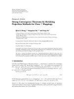
The resulted energies as the function of data frame size
are presented in Figure 1. Generally, the HR transceiver has
nearly one order of magnitude low er effective energy con-
sumption compared to the LR radio. The energy overhead
is nearly equal for both radio types. The energy overhead
is caused mostly by the backoff mechanism and carrier
sensing causing idle listening. The mechanism also necessi-
tates frequent operation mode changes causing significant
startup transient energy consumption. The results clearly
indicate that energy overhead is dominating the energy
consumption of the HR radio. For the LR radio, the energy
overhead is also significant. In practice, busy channel situa-
tions and collisions make the energy overhead even higher
[36].
4. TUTWSN MAC Design and Implementation
In this section, the design of TUTWSN MAC proto-
col is presented, including channel access and network-
ing mechanisms. The main objective for the channel
access mechanism is the minimization of overhead energy,
and thus the maximization of energy efficiency. A spe-
cial focus is on the minimization of collisions, which
increases energy-efficiency and reliability. The main objec-
tives for networking mechanism are low network signal-
ing overhead and high tolerance against unreliable radio
links and node mobility. An important objective for the
entire MAC protocol has been compatibility with a sim-
ple and low-power hardware allowing low-cost imple-
mentation. Neighbor discovery mechanisms are presented
only briefly, since they have been published earlier in
[37, 38].
4.1. TUTWSN Channel Access. The designed TUTWSN
channel access mechanism pursues to maximize energy
efficiency by minimizing idle listening, unnecessary startup
transients, overhearing, control frame overhead, and colli-
sions. These are minimized by two ways.
(i) Predetermined frame exchange moments: nodes
maintain accurate local synchronization and
exchange frames exactly at predetermined moments.
(ii) Reservation based channel access: nodes avoid colli-
sions and the energy overhead of contention mech-
anism by reserving their transmission moments in
advance.
6 EURASIP Journal on Wireless Communications and Networking
1
10
100
1000
0
16
32
48
64
80 96
112
128
Data frame size (Bytes)
Energy (μJ)
Effective
Back-off
Start-up
ACK wait
HR (nRF2401A)
(a)
1
10
100
1000
0 163248648096112128
Data frame size (Bytes)
Energy (μJ)
Effective
Back-off
Start-up
ACK wait
LR (CC1000)
(b)
Figure 1: The effective and overhead energies of nRF2401A (HR)
and CC1000 (LR) platforms.
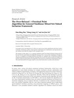
Channel access is based on superfr ames that are repeated
at regular intervals (access cycle) as shown in Figure 2.
A node may act as a cluster head and maintain its own
superframe and/or par ticipate to other superframes as a
member node. The rest of the time, nodes can sleep and
conserve energy. For eliminating collisions, superframes have
locally unique schedules such that they do not overlap
with each other. The superframe interlacing mechanism is
presented in the following sections.
At the beginning of each superframe, a cluster head trans-
mits a beacon. The beacon contains crucial information for
the channel access, networking, and routing. For the channel
TX
RX
TX
RX
Node A
Time
Time
t
A
Uplink boundary Downlink boundary
Idle time
Idle time
Super-
frame
TX
RX
Node B
Time
t
S
Time
Contention
slots
Contention-free
slots
Super-
frame
Beacon
Access cycle
Figure 2: TUTWSN access cycle and superframe.
access, two fields are the most essential: time to the next
superframe, which is used for maintaining synchronization,
and reserved slot allocation table, which is used for granting
transmission rights for associated neighbors.
The beacon is followed by a brief ALOHA-based con-
tention period and a significantly longer contention-free
period. Both channel access periods are further divided
into communication slots that are large enough for a data
transmission with a maximum duration of t
A
,apacket
processing time t
S
during which radio may be on sleep
state, and an acknowledgment. A communication slot is
referred to as uplink when a member transmits and the
cluster head acknowledges, while a downlink slot denotes
that the cluster head transmits. The use of contention-free
slots is preferred, while contention slots are used for control
frames allowing network association and slot reservations. A
node uses contention-based channel access only when it has
queued data for transmission and has not been assigned with
an uplink slot. This oper ation is detailed in Figure 3.
To ensure reliability all data transmission except broad-
casts are acknowledged. The a cknowledgment is transmitted
in the same communication slot with the data frame. While
a WSN protocol might save energy by relying on redundancy
and omitting acknowledgments, taking such approach would
limit the applicability of the protocol. To decrease overhead
due to high redundancy, a higher layer data aggregation
protocol is assumed.
Since the cluster head cannot predict which con-
tention slots will be used, unnecessary reception of slots is
unavoidable causing idle listening. This is common for all
contention-based mechanisms. The reduction of the number
of contention slots reduces the idle listening of cluster
heads, but increases the probability of collisions reducing
network energy efficiency and performance [39, 40]. In the
designed contention mechanism, the energy consumption
is minimized by three ways. First, the reception is always
terminated as soon as an unused contention slot is detected,
or at last when t
A
has expired. Second, the utilization of
EURASIP Journal on Wireless Communications and Networking 7
Success?
Receive
beacon
Finish
ALOHA
Uplink
slots?
Queued
packets?
Success?
More
slots?
Wait until
next reserved slot
TX/RX data
Yes
No
Yes
No
No
Yes
No
Yes
No
Yes
Downlink
slots?
Yes
No
Figure 3: Operation of member node during a superframe.
contention slots is minimized by piggybacking bandwidth
adjustment signaling in data frames. Third, the number of
contention slots is dynamically adjusted according load [41].
The designed contention-free mechanism is inherently
energy efficient, since the utilized reserved slots in each
superframe are determined in advance using bandwidth
adjustment signaling and the slot allocation table. The idle
listening is nearly eliminated, since only utilized slots are
received. A minor idle listening is caused by the inaccuracy
of time synchronization and occasional link failures causing
reception failures in the contention-free slots. Since the
beacon at the beginning of each superframe performs
synchronization, the clock drift is negligible at the slot
boundaries.
4.2. Contention-Based Channel Access. The TUTWSN design
allows contention-based slot access with CSMA/CA princi-
ple. However, our design uses ALOHA-based approach to
avoid the need for carrier sensing. Thus, the protocol can be
implemented with a very simple and low-cost hardware.
The operation on contention-based channel access is
presented in Figure 4. A cluster head indicates the number
of ALOHA slots S
A
in its cluster beacon. This way, a cluster
head can dynamically change the number of slots if slot
usage is high, for example, due to mobility. Next, a node
attempts transmission at a random slot. Only one attempt
per access cycle is allowed. If the transmission fails, a node
assumes collision and increases its ALOHA backoff co unter
(B)uptoB
max
.Then,anodewaitsrandomB
wait
access cycles
before the next transmission attempt. When a transmission
succeeds, node resets its backoff counter (B) thus allowing
ALOHA
Transmit data at
random(1,S
A
) slot
B
= min(B +1,B
max
)
B
wait
= random(0, B
max
)
B
wait
= B
wait
− 1
Success
Fail/skip
TX
succeeds?
B
= 0
Yes
No
B
wait
> 0
No
Yes
Figure 4: Contention-based channel access with ALOHA-based
algorithm.
a contention-based transmission attempted on the next
access cycle.
The number of ALOHA slots (S
A
) and the maximum
backoff value (B
max
)haveatradeoff between energy effi-
ciency, reliability, and channel access latency. Assuming that
ALOHA transmission fails only due to collisions, the trans-
mission success probability during CAP can be expressed as
P
{tx succeeds}=
1 −
1
S
A
N
,(6)
where N is the number of contending nodes. As the design
prefers the use of reserved slots to contention-based slots,
N is usually close to zero. The use of backoff essentially
increases the number of slots (or conversely, reduces the
number of contending nodes per access cycle), thus reducing
collisions. For energy-efficient operation, even one CAP
slot would be enough with sufficiently large B
max
. Finding
optimal parameter values are outside the scope of this paper.
To simplify the analysis in the remainder of this paper, we
use two CAP slots and set B
max
= 1 meaning that a node
can attempt transmission on every access cycle. Assuming
2 CAP slots and 16 reserved slots, the CAP overhead is less
than 12%.
4.3. Contention-Free Channel Access. The contention-free
slot allocation mechanism has a significant effect on the
efficiency of the reserved slot usage. In practice, a cluster
head does not know when a member node has data to
send and therefore cannot optimally assign slots. When too
few reservations are granted, a node must use unreliable
contention-based channel access to transmit its data, while
too many reservations waste capacity and energy.
Next, we identify and examine three contention-free
slot allocation methods: fixed, dynamic, and on-demand
8 EURASIP Journal on Wireless Communications and Networking
Conten-
tion
Contention-free
Beacon
Utilized slot
Slot indication
On-demand reservation:Fixed/dynamic reservation:
Conten-
tion
Contention-free
Figure 5: Fixed, dynamic, and on-demand allocation methods.
allocation. The operation of the methods is presented in
Figure 5.
In the fixed allocation method, a node is granted with
a predetermined amount of reserved slots. A cluster head
indicates the exact slot times in its cluster beacon. The typical
approach, for example, in IEEE 802.15.4, grants the same
amount of reservations for each access cycle. This wastes
capacity when a device does not have data to send on each
access cycle. We propose that the fixed allocations are granted
over a certain time referred to as a reservation period, for
example, 20 slots per a minute. A cluster head distributes
the reservations evenly among the access cycles within the
reservation period. Thus, if node has requested only a few
slots, a slot is not necessarily granted on each access cycle.
A node postpones the forwarding of nondelay critical data
until a slot is granted. This way, the granted slots are fully
utilized, assuming that the reserved capacity matches the
average traffic.
The dynamic allocation method avoids the need for
determining average traffic. Instead, the allocations are
adjusted to match the traffic load of a node, thus reacting to
the changes in traffic l oad. A member node could record its
own traffic and then explicitly request a matching amount
of fixed reservations. However, to reduce communication
overhead in TUTWSN MAC, a cluster head keeps the
record of traffic received f rom its member nodes and adjusts
dynamic reservations accordingly.
In the on-demand allocation method, a node sends an
initial packet on a contention slot. If the node has more
packets in its buffers, it sets a reservation flag piggybacked
on the data packet. Then, a cluster head allocates another
contention-free slot during the same active period. The slot
is indicated to the node in the acknowledgment frame. To
get more slots during an access cycle, the request is repeated
on the granted slots. The problem with the on-demand
allocation method is the use of contention slots, which may
cause collisions. To reduce the collision probability, a node
may wait for a certain time while buffering data frames.
Thewaitinghasatradeoff between latency and reliability,
as waiting decreases the collision-prone contention-based
channel access.
To optimize energy-efficiency of the channel access,
the proposed contention-free slot allocation scheme for
TUTWSN MAC uses a combination of the allocation
methods. A member node is granted with fixed allo-
cations to guarantee certain bandwidth. The amount of
fixed reservations is a deployment specific parameter and
canbezeroinlightlyloadednetworkstoavoidunused
slots. The dynamic allocation method provides additional
capacity on top of the guaranteed bandw idth, thus allowing
nodes to adjust to the traffic conditions. The fixed and
dynamic slot allocations are augmented with the on-demand
allocations, thus providing a method to handle traffic
bursts.
4.4. Network Topology Formation. To reduce the energy
consumption of frame transmissions in large networks,
multihop data routing between nodes is utilized [42, 43].
Frames are routed from a source to a destination along a
chain of low-energy hops. Each node along the chain receives
data from a neighbor (child) one hop closer to the source,
maintains synchronization with a next-hop node (parent)
by periodically receiving its beacons, and transmits data
according to time slot assignments.
The selection of network topology between flat and
clustered affects significantly network energy consumption
and bandwidth utilization [21, 41 , 44]. In the flat topol-
ogy, all nodes participate in data routing and consume
nearly equally power and network bandwidth. In the
clustered topology, a network is formed as interconnected
star networks. The master of each star is a cluster head,
while other nodes are leaf nodes. Cluster heads utilize a
majority of energy and bandwidth by managing super-
frames and exchanging data with other clusters. Leaf nodes
synchronize themselves with a superframe schedule and
transmit data on demand without the need of their own
superframes, which reduces the bandwidth utilization of a
network.
The designed network topology is based on the clustered
topology. Each cluster consists of a cluster head (headnode),
leaf nodes (subnodes), and associated headnodes (child
headnodes) from neighboring clusters. The operation of
a child headnode in a next hop cluster is similar with
a subnode, which receives beacons and transmits data
according to time slot assignments.
The utilization of a clustered topolog y is rationalized by
a simple analysis, which considers the energy consumptions
of clustered and flat topologies using the TUTWSN channel
access mechanism. The analysis assumes that the energy
consumptions of frame transmissions (E
TX
) and receptions
(E
RX
) are equal for all frame types, which is realistic for
the TUTWSN channel access utilizing a low-power radio.
Moreover, the density of cluster heads in the clustered
topology is assumed adequate for maintaining optimal hop
lengths. Therefore, the number of required data and ACK
frame exchanges for flat and clustered topologies is equal, as
the entire network is considered.
A router node is defined as any node in the flat
topology, and a cluster head in the clustered topology. The
energy overhead of the router node (E
OR
) consists of the
transmissions and receptions of beacons, and the reception
of S
A
contention slots. For one access cycle, the energy
overhead is
E
OR
= E
TX
+
(
S
A
+1
)
E
RX
. (7)
EURASIP Journal on Wireless Communications and Networking 9
The energy overhead of a leaf node (E
OL
) using
TUTWSN channel access is caused by the reception of
beacons. Hence, for one access cycle, E
OL
equals to E
RX
.
In the flat topology, all nodes have equal energy overhead,
which equals to E
OR
. In the clustered topology, where each
cluster consists of n
S
leaf nodes, the average energy overhead
per a node (E
OC
)is
E
OC
=
E
TX
+
(
S
A
+1+n
S
)
E
RX
n
S
+1
. (8)
If n
S
= 0, then E
OC
= E
OR
. This is clear, since all
nodes are cluster heads and the network is similar with the
flat topology. As n
S
increases, E
OC
decreases, and when n
S
→∞, then E
OC
→ E
RX
, which equals to E
OL
. Hence, the
clustered topology has always lower energy overhead than
the flat topology, assuming that the network has at least one
leaf node. The energy efficiency of clustering is even more
obvious, when cluster heads aggregate received data reducing
the amount of forwarded data [44].
Network connectivity between clusters can be formed
as a cluster-mesh or a cluster-tree topology. In the cluster-
mesh topology, each cluster head maintains connectivity
with all neighboring cluster heads resulting robust network,
but higher energy consumption. In the cluster-tree topology,
each cluster head maintains connectivit y with one cluster
head only, which is one hop closer to a sink locating at the
root of the tree. This improves energy efficiency, but reduces
the tolerance against link failures due to low connectivity.
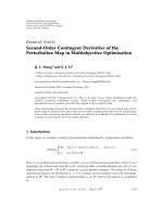
To combine the strengths of cluster-tree and cluster-
mesh topologies, we present a multi-cluster-tree topology.
The multi-cluster-tree topology consists of multiple super-
positioned cluster-tree networks. An example multi-cluster-
tree topology is illustrated in Figure 6, where arrows indicate
the directions of uplink routing paths. Each subnode and
headnode maintains synchronization with several (k)neigh-
bors by receiving their beacons. This allows the adjustment
of connectivity for both subnodes and headnodes allowing a
tradeoff between network robustness and energy consump-
tion. Compared to the cluster-tree topology that supports
only one route to a single sink the multi-cluster-tree allows
the utilization of multiple sinks, multiple routes, and load
balancing between headnodes. The value of k is uniform
for entire network and it is selected before a deployment
according to expected network dynamics. According to
measurements with TUTWSN nodes, an optimal value for
k is between 2 and 4.
4.5. Superframe Interlacing. For guaranteeing contention-
free channel access in a multihop network, the overlapping of
superframes in two-hop neighborhood (interference range)
is eliminated by interlacing. Typically, interlacing is imple-
mented by time div ision, for example in IEEE 802.15.4 [24],
DMAC [45], SRSA [46], and TRAMA [31]. The time division
limits network density especially when the superframe length
is relatively long compared to the access cycle length. In
the designed superframe interlacing mechanism, scalability
is improved by time and frequency division. For reasoning
this, a short analysis of the maximum scalability is presented.
Subnode
Headnode
Sink
Cluster-tree 1
Cluster-tree 2
Figure 6: Multi-cluster-tree network topology (k = 2).
The maximum number (α) of nodes in an interference
area can be determined by the access cycle length (T
AC
), the
superframe length, the average number of subnodes in each
cluster, and the number of utilized noninterfering frequency
channels (n
CH
)as
α
=
T
AC
n
CH
(
1+n
S
)
2
(
1+S
A
+ S
R
)(
t
A
+ t
S
)
+ t
guard
,(9)
where S
A
and S
R
are the maximum number of contention
and contention-free slots, t
guard
is a short guard time between
consecutive superframes. α is maximized by maximizing T
AC
,
n
CH
,andn
S
, and by minimizing t
A
and t
S
.Itcanbeclearly
seen in the equation that by utilizing a high data-rate radio
operating at a wide frequency band provides the highest
scalability.
In the current 2.4 GHz TUTWSN implementation,
T
AC
= 4 seconds, n
CH
= 20, n
S
= 8, S
A
= 4, S
R
= 8, t
A
+ t
S
=
10 ms, and t
guard
= 100 ms. Thus, α equals to 2000 nodes per
an interference area. If only one channel is used (n
CH
= 1), α
would be reduced to 100 nodes per an interference area.
In the designed superframe interlacing mechanism, each
headnode selects semirandomly a time slot and a frequency
channel (superslot) for its superframe among the free slots
detected by a network scan. The simple randomization min-
imizes the energy overhead of signaling traffic. The superslot
is selected at a node startup and if interferences are detected
by increased link er ror rate [41]. The energy consumption
of network scans is reduced by using a network signaling
channel [37] and by proactively signaling neighborhood
information [38].
5. Performance Analysis of
TUTWSN and Related Proposals
This chapter presents p erformance models for analyzing
the power consumptions of the most essential low-power
10 EURASIP Journal on Wireless Communications and Networking
channel access mechanisms and comparing them against
the designed TUTWSN MAC. The focus is on data and
ACK frame exchanges and on the maintenance of link
synchronization by a beacon or SYNC frame exchange.
The performance of TUTWSN MAC is compared against
the following MAC protocols: T-MAC [23]andB-MAC[15],
which are well-known synchronized and unsynchronized
low dut y-cycle protocols, X-MAC [18]andSCP-MAC[20],
which are two interesting proposals for unsynchronized
protocols, and IEEE 802.15.4 [24], which is standardized
technology for WSNs. For comparison, an ideal MAC
protocol is defined and modeled.
The following performance models are based on the
analysis of Yoon presented in [47]. For this paper, the
set of models has been extended by IEEE 802.15.4 and
TUTWSN MAC protocols. In addition, the effects of startup
transitions, contention windows, and crystal tolerance have
been modeled more accurately. In addition, the models and
their presentation have been simplified and clarified.
The performance models are derived using the following
assumptions:
(i) each sensor node measures one sensor sample and
forwards it to a next-hop node during one data
generation interval;
(ii) each data frame is followed by an ACK for fair
comparison;
(iii) there are no transmission errors nor collisions;
(iv) there is no contention, and carrier sense attempts
produceanidleresult;
(v) the power consumption of idle listening equals to the
reception mode power;
(vi) the active time of MCU equals to the active time of
radio.
Therefore, the performance models can focus on the
power consumption of the channel access mechanisms, while
the effects of data processing, contention, and control frame
exchanges are eliminated. For contention-based protocols,
obtained results are slightly better than in practice with
contention. As TUTWSN MAC utilizes contention-free
mechanism for data and ACK exchanges, the obtained results
for TUTWSN are realistic.
5.1. Utilized Parameters. For determining the channel access
models, all essential parameters describing the characteristics
of a sensor node platform, application, and network topology
are identified. The sensor node platform is defined by the
following parameters:
ε: crystal tolerance of a wake up timer,
P
Y
: the power consumed for Y,whereY ∈{RX (receive),
S (sleep), TX (transmit)
},
R: the data rate of a r adio, and
t
ST
: radio startup transient duration (crystal running).
Application and network topology are defined by the
following parameters:
L
X
: the length of frame X,whereX ∈{ACK,B(beacon
or SYNC), CTS, DA TA, P (preamble), RTS
},
n: the number of direct neighbors for a given node,
n
DL
: the number of descendent nodes of a given node
in the routing tree, that is, the number of data
frames the node needs to forward during one data
generation interval,
n(i): the number of nodes whose transmissions can be
received by node i, and
T
DA T A
: data generation interval in each node.
In addition, there are protocol implementation specific
parameters. Generally utilized parameters of that kind are:
t
CCA
: the time for a clear channel assessment or carrier
sensing,
t
CW
: contention window length in CSMA,
t
sleep
: sleep period length,
T
AC
: access cycle length or channel polling interval, and
T
SYNC
: transmission interval of SYNC or beacon frames.
5.2. Modeled Network Topology. The modeled network topol-
ogy describes the performance of a single link. Its parameters
can be adjusted to model an arbitrary multihop topology,
where each link can have different parameters. The limitation
of the topology is that data is forwarded only to one hop
node, which applies to networks having one data consumer
(sink). Energy consumptions are analyzed for a router node
(A), and a leaf node (B) presented in Figure 7.Bothnodes
have eight neighbors (n), which may cause overhearing and
interferences for the channel access. Data generation interval
(T
DA T A
) is equal for each node, and it varies from 1 second
to 1000 seconds. Arrows in the figure indicate data routing
directions. The traffic load is accumulated in routers, since
they transmit their ow n data and the multihop routed data
from n
DL
nodes. For example, the router node A routes data
from three nodes (n
DL
={B, D, E}), while the router node
C routes data from four nodes (n
DL
={A, B, D, E}). This
increases the power consumption of these routers, but also
the overhearing and interferences among other nodes in their
transmission range.
Average power consumptions (P) for each protocol are
calculated by transmission (t
TX
) and reception (t
RX
)duty
cycles, and their power consumptions as
P
= t
TX
P
TX
+ t
RX
P
RX
+
(
1 − t
TX
− t
RX
)
P
S
. (10)
The duty cycle is determined by dividing the duration
of an activity by the interval of the activity resulting in
a percentage value of the activity. Data exchanges are
normalized by T
DA T A
during which all nodes in the network
generate exactly one data frame. Similarly, the transmission
and reception activity for maintaining synchronization is
normalized by T
SYNC
.
EURASIP Journal on Wireless Communications and Networking 11
A
B
C
D
E
Figure 7: Network topology for channel access comparison.
ACK
s
Time
Time
TX
RX
TX
RX
Source
Target
s
s
s
t
ST
Data
Figure 8: The activity of radio in Ideal-MAC.
5.3. Ideal-MAC. First, an ideal MAC (Ideal-MAC) protocol
[47] is defined. All nodes can exchange data and ACK frames
without the need of any synchronization or contention
mechanism. Nodes can sleep all the time between frame
exchanges. Hence, the Ideal-MAC does not cause any idle
listening or control frame overhead.
The required activity for exchanging one data frame is
presented in Figure 8. Although MAC is ideal and practically
impossible to implement, a sensor node platform is realistic
and each data transmission and reception is preceded by a
radio startup transient (t
ST
). Thus, t
TX
and t
RX
for a leaf node
are
t
TX
=
t
ST
+
L
DATA
R
1
T
DATA
,
t
RX
=
t
ST
+
L
ACK
R
1
T
DATA
.
(11)
Therouternodereceivesdataframesfromn
DL
leaf nodes,
transmits them ACKs, forwards the received and own data
frames to a parent and receives ACKs.
Thus, t
TX
and t
RX
for the router are
t
TX
=
t
ST
+
L
DA T A
R
n
DL
+1
T
DA T A
+
t
ST
+
L
ACK
R
n
DL
T
DA T A
. (12)
t
RX
=
t
ST
+
L
DA T A
R
n
DL
T
DA T A
+
t
ST
+
L
ACK
R
n
DL
+1
T
DA T A
,
(13)
5.4. Unsynchronized Low Duty-Cycle Protocols. Next, models
for unsynchronized low duty-cycle protocols are defined.
The unsynchronized low duty-cycle protocols allow the
transmission of data frames on-demand basis wi thout the
need to wait for an active period. Yet, the nodes must poll
the channel frequently for detecting the transmissions from
other nodes.
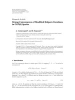
5.4.1. B-MAC. B-MAC [15] uses the LPL scheme, where
nodes sleep (t
sleep
), wake up ( t
ST
) and poll channel (t
CCA
)
periodically at T
AC
intervals. The frame exchanges of B-MAC
are presented in Figure 9.
The normalized channel polling time (t
POLL
)is
t
POLL
=
t
ST
+ t
CCA
T
AC
. (14)
Each transmission is preceded by a carrier sensing (t
CCA
)
and a preamble transmission lasting T
AC
.Thus,t
TX
for a leaf
node is
t
TX
=
t
ST
+ T
AC
+
L
DA T A
R
1
T
DA T A
. (15)
In B-MAC, all data in a radio range is received. As a
leaf node has n neighbors, and a router in a range forwards
n
DL
data fr ames from leaf nodes, totally n + n
DL
data frames
are received during T
DA T A
. Since channel is polled randomly,
average preamble reception time is a half of T
AC
.Thus,t
RX
for the leaf node is
t
RX
= t
POLL
+
T
AC
2
− t
CCA
+
L
DA T A
R
n + n
DL
T
DA T A
+
t
ST
+
L
ACK
R
1
T
DA T A
.
(16)
The operation of the router node is similar to the leaf
node, except the amount of exchanged data. The normalized
transmission and reception times for the B-MAC router are
t
TX
=
t
ST
+ T
AC
+
L
DA T A
R
n
DL
+1
T
DA T A
+
t
ST
+
L
ACK
R
n
DL
T
DA T A
,
t
RX
= t
POLL
+
T
AC
2
− t
CCA
+
L
DA T A
R
n + n
DL
+1
T
DA T A
+
t
ST
+
L
ACK
R
n
DL
+1
T
DA T A
.
(17)
The power consumption reaches its unique minimum at an
optimal polling interval (T
∗
AC
) obtained by setting ∂(t
TX
P
TX
+
t
RX
P
RX
)/∂T
AC
= 0. Performance results are calculated using
the optimal polling interval of the router, which is
T
∗
AC
=
T
DA T A
(
t
ST
+ t
CCA
)
(
n
DL
+1
)
P
TX
/P
RX
+
(
n + n
R
+1
)
/2
. (18)
5.4.2. SCP-MAC. SCP-MAC [20] replaces the long preamble
with a short wake-up tone by waking up the senders and the
receiver at the same time.
12 EURASIP Journal on Wireless Communications and Networking
Time
Time
TX
RX
TX
RX
Source
Target
t
CCA
t
CCA
t
sleep
Preample
T
AC
T
AC
T
AC
/2
s
s
s
s
s
s
s
t
ST
ACK
Data
Figure 9: The activity of radio in B-MAC.
Data
Time
Time
TX
RX
TX
RX
Source
Target
t
sleep
T
AC
/2
P
t
p
2t
p
+ t
al
P
s
s
s
s
P
s
s
s
s
s
s
s
s
s
ACK
ACK
t
al
s
T
AC
t
ST
Figure 10: The activity of radio in X-MAC.
The best-case situation is considered, where all syn-
chronization signaling is piggybacked with data frames.
Thus, the synchronization does not cause control frame
exchanges. SCP-MAC utilizes similar channel polling than
B-MAC, and t
POLL
equals to (13). The duration of the wake-
up tone (t
TONE
) i s determined according to the clock drift
(ε), the rate of frame receptions containing synchronization
information, and the minimum tone duration (t
CCA
)to
detect a transmission. Thus, t
TONE
is
t
TONE
=
4T
DA T A
ε
n + n
DL
+ t
CCA
.
(19)
A data frame transmission consists of the wake-up
tone, and the frame transmission. SCP-MAC utilizes two
contention windows (CW1 and CW2) with the maximum
length of t
CW
/2. Thus, an average backoff time in each
contention window is t
CW
/4 during which the source node
is asleep.
After a startup transient, the destination node receives
on average halves of the wake-up tone and the second
contention window. Data frames are piggybacked with
synchronization data (SB). Thus, t
TX
and t
RX
of the SCP-
MAC leaf node are
t
TX
=
2t
ST
+ t
TONE
+
L
SB
+ L
DA T A
R
1
T
DA T A
,
t
RX
= t
POLL
+
3t
ST
+2t
CCA
+
L
ACK
2
1
T
DA T A
+
3t
ST
+
t
TONE
2
+
t
CW
4
+ t
CCA
+
L
SB
+ L
DA T A
R
×
n + n
DL
T
DA T A
.
(20)
The SCP-MAC router transmits n
DL
+ 1 data frames to a
next hop node, and ACKs to the leaf nodes. Thus, t
TX
and t
RX
of the SCP-MAC router node are
t
TX
=
2t
ST
+ t
TONE
+
L
SB
+ L
DA T A
R
n
DL
+1
T
DA T A
+
t
ST
+
L
ACK
R
n
DL
T
DA T A
,
t
RX
= t
POLL
+
3t
ST
+2t
CCA
+
t
ACK
R
n
DL
+1
T
DA T A
+
3t
ST
+
t
TONE
2
+
t
CW
4
+
L
SB
+ L
DA T A
R
n + n
DL
+1
T
DA T A
.
(21)
For achieving the best energy efficiency, a node should
only poll the channel when there is a transmission from
a neighbor. Performance results are calculated using the
optimal polling interval of the router, which is
T
∗
AC
=
T
DA T A
n
DL
+1
. (22)
5.4.3. X-MAC. In X-MAC [18], each data frame transmis-
sion is preceded by the strobed preamble, as presented in
Figure 10. The minimum channel polling time to receive at
least one entire preamble (P) equals to the lengths of two
preambles (t
p
) and one ACK (t
al
). The normalized channel-
polling time in X-MAC is
t
POLL
=
2t
p
+ t
al
T
AC
, (23)
EURASIP Journal on Wireless Communications and Networking 13
where
t
p
= t
ST
+
L
P
R
,
t
al
= t
ST
+
L
ACK
R
.
(24)
Assuming uniform distribution of wake-up moments,
the average length of the strobed preamble is a half of
the wake up period (T
AC
), during which T
AC
/(2(t
p
+t
al
))
preambles are transmitted. Overhearing is limited to the
channel polling time. Hence, t
TX
and t
RX
the leaf node are
t
TX
=
⎛
⎝
T
AC
2
t
p
+ t
al
t
p
+ t
ST
+
L
DA T A
R
⎞
⎠
1
T
DA T A
,
t
RX
= t
POLL
+
⎛
⎝
T
AC
2
t
p
+ t
al
+1
⎞
⎠
t
al
T
DA T A
.
(25)
As t he router node receives and f orwards data frames
from n
DL
nodes, the normalized transmission and reception
times of the X-MAC router node are
t
TX
=
⎛
⎝
T
AC
2
t
p
+ t
al
t
p
+
L
DA T A
R
⎞
⎠
n
DL
+1
T
DA T A
+
2t
al
n
DL
T
DA T A
,
t
RX
= t
POLL
+
⎛
⎝
T
AC
2
t
p
+ t
al
+1
⎞
⎠
t
al
(
n
DL
+1
)
T
DA T A
+
t
ST
+
L
DA T A
R
n
DL
T
DA T A
.
(26)
The power consumption reaches its unique minimum
at an optimal polling interval (T
∗
AC
) obtained by set-
ting ∂P/∂T
AC
= 0.
Performance results are calculated using the optimal
polling interval of the router, which is
T
∗
AC
=
2T
DA T A
t
p
+ t
al
2t
p
+ t
al
t
p
P
TX
/P
RX
+ t
al
(
n
DL
+1
)
. (27)
5.5. Synchronized Low Duty-Cycle Protocols. Next, the syn-
chronized low duty-cycle protocols are modeled. In synchro-
nized protocols data transmissions occur in active periods as
bursts. We define n
F
as the number of data transmission in
each active period. For comparability, n
F
is assumed to be
equal for all synchronized protocols. Thus, the optimal access
cycle length (T
∗
AC
) for synchronized protocols can be defined
as
T
∗
AC
=
n
F
T
DA T A
n
DL
+1
. (28)
5.5.1. T-MAC. In T-MA C [23], each node polls channel for
RTS messages at T
AC
intervals, as presented in Figure 11.
If no traffic exists, radio is turned off after a period of T
A
.
Hence, the normalized channel polling time without trafficis
t
POLL
=
t
ST
+ T
A
T
AC
,
(29)
where
T
A
= t
ST
+ t
CW
+ t
RTS
.
(30)
A data frame transmission consists of a random delay
within a Contention Window (CW) being followed by an
RTS - CTS - DATA - ACK frame exchange. L
B
bytes long
SYNC frames are transmitted at T
SYNC
intervals using a
random delay within CW. For maximum energy-efficiency,
adaptive listening and virtual clusters are assumed. Accord-
ing to received RTS frames, nodes are in sleep mode during
the transmissions intended to other nodes. Thus, t
TX
and t
RX
for the leaf node are
t
TX
=
2t
ST
+
L
RTS
+ L
DA T A
R
1
T
DA T A
+
t
ST
+
L
B
R
1
T
SYNC
,
t
RX
= t
POLL
+
2t
ST
+
t
CW
2
+
L
RTS
R
n + n
DL
T
DA T A
+
2t
ST
+
L
CTS
+ L
ACK
R
1
T
DA T A
+
t
ST
+ t
CW
−
L
B
R
1
T
SYNC
.
(31)
Therouternodereceivesdataframesfromn
DL
nodes,
transmits n
DL
+ 1 frames to a next-hop node, and transmits
and receives SYNC frames. Thus, t
TX
and t
RX
for the T-MAC
router node are
t
TX
=
2t
ST
+
L
RTS
+ L
DA T A
R
n
DL
+1
T
DA T A
+
2t
ST
+
L
CTS
+ L
ACK
R
n
DL
T
DA T A
+
t
ST
+
L
B
R
1
T
SYNC
,
t
RX
= t
POLL
+
3t
ST
+
t
CW
2
+
L
RTS
+ L
DA T A
R
n
DL
T
DA T A
+
t
ST
+
t
CW
2
+
L
RTS
R
n + n
DL
+1
T
DA T A
+
2t
ST
+
L
CTS
+ L
ACK
R
n
DL
+1
T
DA T A
+
t
ST
+ t
CW
−
L
B
R
1
T
SYNC
.
(32)
5.5.2. IEEE 802.15.4. For obtaining the best energy efficiency,
IEEE 802.15.4 [24] is analyzed in the beacon-enabled mode,
with inactive time, and employing a cluster-tree network
topology. Nodes maintain synchronization by receiving
beacon frames from a parent at the beginning of active
periods. Beacons are transmitted by cluster heads only. The
required activity of radio is presented in Figure 12.
As the beacons are tr ansmitted at T
AC
intervals, the
normalized beacon reception (polling) time is
t
POLL
=
t
ST
+2T
AC
ε +
L
B
R
1
T
AC
. (33)
14 EURASIP Journal on Wireless Communications and Networking
Data
ACK
Time
Time
TX
RX
TX
RX
Source
Target
B
CTS
RTS
t
CW
/2
t
CW
s
s
s
s
s
s
s
s
s
s
s
s
s
B
Time
s
T
A
s
s
SYNC
SYNC
T
SYNC
T
A
T
AC
s
s
1. data exchange 2.
−n. data
exchanges
s
Active
period
T
AC
s
t
ST
···
Figure 11: The activity of radio in T-MAC.
Data
TX
RX
TX
RX
Source
Target
B
t
CW
/2
s
s
s
s
s
s
s
s
t
CCA
Data
ACK
ACK
t
CW
/2
sss
s
s
s
t
CCA
2T
AC
ε
Time
Time
Time
t
CAP
T
AC
B
1. data exchange 2. data exchange
CAP
B
CAP
s
3.
−n. data
exchanges
t
ST
···
Figure 12: The activity of radio in IEEE 802.15.4.
A data frame transmission is preceded by a ran-
dom backoff delay and two Clear Channel Assessment
(CCA) operations [24]. IEEE 802.15.4 utilizes blind back-
offs, where nodes spend the backoff delay in the sleep
mode.
A data frame is followed by an ACK, which is transmitted
within a maximum waiting time of 864 μs. Assuming
the best case situation, where the hardware processes the
received frame instantly, ACK is transmitted without a
delay. Thus, t
TX
and t
RX
for the IEEE 802.15.4 leaf node
are
t
TX
=
t
ST
+
L
DA T A
R
1
T
DA T A
,
t
RX
= t
POLL
+
3t
ST
+2t
CCA
+
L
ACK
R
1
T
DA T A
.
(34)
The IEEE 802.15.4 router node (coordinator) transmit
beacons, receives entire CAP except ACK transmissions, and
forward data to a next hop node. Thus, t
TX
and t
RX
for the
IEEE 802.15.4 router node are
t
TX
=
t
ST
+
L
B
R
1
T
AC
+
t
ST
+
L
DA T A
R
n
DL
+1
T
DA T A
+
t
ST
+
L
ACK
R
n
DL
T
DA T A
,
t
RX
= t
POLL
+
t
CAP
T
AC
−
t
ST
+
L
ACK
R
n
DL
T
DA T A
+
3t
ST
+2t
CCA
+
L
ACK
R
n
DL
+1
T
DA T A
.
(35)
For achieving the maximum energy efficiency, analysis
results are determined using the minimum CAP length,
where the required frame exchanges can be performed.
The minimum CAP length is
t
CAP
=
4t
ST
+
t
CW
2
+2t
CCA
+
L
DA T A
+ L
ACK
R
n
F
. (36)
EURASIP Journal on Wireless Communications and Networking 15
5.5.3. TUTWSN MAC. For comparison, the energy con-
sumption of TUTWSN MAC is modeled. Due to the
stationary network, the following analysis considers the
basic channel access mechanism without the networking
mechanisms. Each node maintains synchronization with one
parent. Superframe contains S
A
contention slots and the
required number of contention-free slots. The activ ity of
radio in TUTWSN MAC is presented in Figure 13.
In TUTWSN MAC, the normalized channel polling time
t
POLL
is similar with IEEE 802.15.4. The leaf node (subnode)
receives the beacons and transmits data using a contention-
free slot. Thus, t
TX
is similar with IEEE 802.15.4 leaf node,
and t
RX
for the leaf node is
t
RX
= t
POLL
+
t
ST
+
L
ACK
R
1
T
DA T A
. (37)
The TUTWSN router node (headnode) receives and
transmits beacons, receives S
A
/T
AC
contention slots and
n
DL
/T
DA T A
contention-free slots, and transmits received and
own generated data to a parent in contention-free slots. Thus,
t
TX
and t
RX
for the TUTWSN router are
t
TX
=
t
ST
+
L
B
R
1
T
AC
+
t
ST
+
L
ACK
R
n
DL
T
DA T A
+
t
ST
+
L
DA T A
R
n
DL
+1
T
DA T A
,
(38)
t
RX
= t
POLL
+
t
ST
+
L
DA T A
R
S
A
T
AC
+
n
DL
T
DA T A
+
t
ST
+
L
ACK
R
n
DL
+1
T
DA T A
.
(39)
5.6. Results. By utilizing parameter values presented in
Table 2, average power consumptions are determined for the
High Rate (HR) platform utilizing Nordic Semiconductor
nRF2401A transceiver and for the Low Rate (LR) platform
utilizing TI CC1000 transceiver.
The results for the HR platform are presented in
Figure 14. According to the results, synchronized protocols
outperform clearly unsynchronized proposals in the ana-
lyzed network. For both node types, the order of power
consumptions is the same. B-MAC results in the highest
power, while TUTWSN MAC perfor ms closest to the Ideal-
MAC.
As data generation interval increases from 1 second to
1000 seconds, the power consumptions of the Ideal-MAC
leaf and router nodes are 68 μWto37μW, and 270 μWto
37 μW, respectively. The power consumption of TUTWSN
MAC leaf and router nodes are 23.4% to 6.54%, and 18.8%
to 6.60% higher than the Ideal-MAC and the same data
generation intervals. IEEE 802.15.4 performs the second best
and results in 80.4% to 6.64% and 229% to 8.14% higher
power consumption than the Ideal-MAC.
The utilization of LR platform increases power consump-
tions, as presented in Figure 15.However,TUTWSNMAC
maintains its energy efficiency resulting in the lowest power
consumption. The power consumptions of the Ideal-MAC
leaf and router nodes are 171 μWto37μW, and 945 μWto
Table 2: Utilized parameter values.
Parameter Value (HR) Value (LR)
E 20 ppm 20 ppm
L
ACK
, L
CTS
, L
RTS
, L
P
8B 8B
L
B
, L
DA T A
32 B 32 B
L
SB
(SCP-MAC) 2 B 2 B
n 88
n
F
88
n
DL
33
P
RX
60.2 mW 25.4 mW
P
S
37 μW37μW
P
TX
34.7 mW 29.9 mW
R 1 Mbps 76.8 kbps
S
A
(TUTWSN) 2 2
T
SYNC
(T-MAC) 90 seconds 90 seconds
t
CCA
128 μs 256 μs
t
CW
2ms 4ms
t
ST
195 μs 250 μs
38 μW, respectively. The power consumption of TUTWSN
MAC leaf and router nodes are 27.1% to 2.85%, and 20.2%
to 3.18% higher than the Ideal-MAC and the same data
generation intervals. IEEE 802.15.4 performs the second best
and results in 42.1% to 2.92% and 66.3% to 4.33% higher
power consumption than the Ideal-MAC.
The results indicate that the designed channel access
mechanism achieves higher energy efficiency than the most
essential existing low-power MAC protocols. Depending on
the traffic loading, radio type, and data routing capability, the
energy overhead of TUTWSN MAC is only 2.85% to 27.1%
compared to the Ideal-MAC. The high energy efficiency is
achieved in both leaf and router nodes.
6. Simulations of TUTWSN and IEEE 802.15.4
The analytical models for TUTWSN MAC and IEEE 802.15.4
were verified with Network Simulator 2 (NS2). The other
protocols were not simulated as the basic versions of their
models are validated in [47]. The simulations were based on
the HR platform as presented in Ta b le 2 with the exception
of the data rate, which was configured to 250 kbps data rate
to conform the 802.15.4 physical layer specification.
The simulation topology consisted of a sink, a router
node, and three leaf nodes. TUTWSN MAC and IEEE
802.15.4 were configured to comparable performance in
respect of delays and throughput. Both protocols used
2 s econds access cycle length. The active period length in
802.15.4 was 0.25 second, whereas TUTWSN MAC used
4 ms slot length and up to 18 reserved slots. The TUTWSN
reservations were adjusted according to the data generation
interval. For example, a node had one reservation per 10
access cycles when data interval was 20 seconds. In addition,
a node could request more reservations by setting a flag in
its data transmission. The cluster head indicated an allocated
slot in its acknowledgment frame.
16 EURASIP Journal on Wireless Communications and Networking
Data
TX
RX
TX
RX
Source
Target
B
s
s
s
s
s
s
2T
AC
ε
Time
Time
Time
T
AC
Superframe
s
s
Data
ACK
ACK
s
s
s
s
···
···
S
A
contention
slots
1.
contention-
free slot
2.
contention-
free slot
Superframe
Sleep
3.
−n.
contention-
free slots
t
ST
Figure 13: The activity of radio in TUTWSN MAC.
0.01
0.1
1
10
1 10 100 1000
Data generation interval (s)
Leaf node power (mW)
B-MAC
X-MAC
SCP-MAC
T-MAC
802.15.4
TUTWSN
Ideal-MAC
(a)
0.01
0.1
1
10
1 10 100 1000
Data generation interval (s)
Router node power (mW)
B-MAC
X-MAC
SCP-MAC
T-MAC
802.15.4
TUTWSN
Ideal-MAC
(b)
Figure 14: Power consumption comparison using the High Rate (HR) platform.
6.1. Model Verification. The difference between simulated
and modeled power consumptions as the function of data
generation interval is shown in Figure 16. To determine the
energy efficiencies of the MAC schemes, the power con-
sumptions were measured after network construction and
therefore network scans and route construction messaging
are excluded.
According to simulations, the power consumption of
TUTWSN is significantly lower than IEEE 802.15.4. As the
data generation interval ranges from 1 to 1000 seconds, the
power consumption of a leaf node is 0.12 mW–0.068 mW
in TUTWSN and 0.33 mW–0.078 mW in IEEE 802.15.4.
In a router node, the power consumption of TUTWSN is
0.55 mW–0.15 mW, which is over one order of magnitude
lower than in IEEE 802.15.4 being 7.78 mW–7.5 mW.
The difference between modeled and simulated power
consumptions in an IEEE 802.15.4 router is below 1%. In
a leaf node, the simulated power consumption is 12%–
63% higher than modeled, because the models do not
consider collisions. As several nodes compete over the
medium, collision probability and therefore retransmissions
and energy consumption increase as data generation interval
decreases.
The simulated power consumption of the TUTWSN
MAC is within 5% of the modeled values. Slig ht variation
in the simulation results is caused by the suboptimal amount
of reservations.
6.2. Slot Allocation Methods. The slot allocation methods
were tested with the configuration listed in Table 3. When
EURASIP Journal on Wireless Communications and Networking 17
0.01
0.1
1
10
1 10 100 1000
Data generation interval (s)
Leaf node power (mW)
B-MAC
X-MAC
SCP-MAC
T-MAC
802.15.4
TUTWSN
Ideal-MAC
(a)
0.01
0.1
1
10
1 10 100 1000
Data generation interval (s)
Router node power (mW)
B-MAC
X-MAC
SCP-MAC
T-MAC
802.15.4
TUTWSN
Ideal-MAC
(b)
Figure 15: Power consumption comparison using the Low Rate (LR) platform.
−2
−1
0
1
2
3
4
5
0.01
0.1
1
10
1101001000
Difference to model (%)
Simulated power (mW)
Data generation interval (s)
Leaf (mW)
Router (mW)
Leaf (%)
Router (%)
TUTWSN
(a)
−10
0
10
20
30
40
50
60
70
0.01
0.1
1
10
1 10 100 1000
Difference to model (%)
Simulated power (mW)
Data generation interval (s)
IEEE 802.15.4
Leaf (mW)
Router (mW)
Leaf (%)
Router (%)
(b)
Figure 16: Difference between simulated and modeled power consumptions in TUTWSN and IEEE 802.15.4.
fixed reservations were used, each leaf node was g ranted one
contention-free slot at every second access cycle, equaling to
64 bps bandwidth. If a node was granted with a slot, but had
nothing to send, the node yielded its reservation by sending
a control frame to the cluster head. The cluster head did
not reply to the control frame. A node used the contention-
based channel access to send data and to request on-demand
reservations if a reserved slot was not granted within two
access cycles (4 seconds). To obtain a realistic tr a fficpattern,
nodes generated Poisson distributed traffic.
18 EURASIP Journal on Wireless Communications and Networking
Table 3: Configurations used in the slot allocation method
simulations.
Configuration
Fixed
allocations
On-demand
reservations
Dynamic
reservations
On-demand
not used Yes no
On-demand + fixed
64 bps Yes no
Dynamic
not used Yes yes
0
2
4
6
8
1 10 100
Per-hop Latency (s)
Data generation interval (s)
On-demand
On-demand + fixed
Dynamic
Ideal
Figure 17: One-hop latency with different contention-free slot
allocation methods.
The simulation results of one-hop latency with the
three slot allocation methods are presented in Figure 17.
As 2 seconds access cycle length was used, the ideal average
latency per hop is 1 second. The on-demand method has
the highest l atency, since the node buffers packets for two
access cycles before sending a packet in a contention slot.
The average latency decreases on shorter data generation
intervals, as several packets can be forwarded at the same
access cycle. When the on-demand method is combined with
fixed al locations, the latency remains the same regardless of
data generation interval, since the node receives a slot on
every other access cycle. The dynamic allocation method has
nearly optimal latency, when traffic load is high. Yet, the
latency increases on low traffic loads, since the probability
that a cluster head grants a reserved slot just after the node
has new data to send decreases. The reason is that the interval
of granting data slots increases with the data generation
interval.
The contention-based slot utilization and the efficiency
of the contention-free slot u sage, measured as ratio between
utilized and wasted slots, are shown in Figures 18 and
19. The on-demand method does not waste capacity, as
reservations are requested only when needed. However, the
drawback of the method is the high contention slot usage that
can cause collisions. The contention-based channel access
is eliminated, when the on-demand allocation method is
0
10
20
30
40
50
1
10 100
Contention slot utilization (%)
Data generation interval (s)
On-demand
On-demand + fixed
Dynamic
Figure 18: Contention slot utilization with different contention-
free slot allocation methods.
0
20
40
60
80
100
1 10 100
Contention-free slot utilization (%)
Data generation interval (s)
On-demand
On-demand + fixed
Dynamic
Figure 19: Utilization of granted contention-free slots with differ-
ent contention-free slot allocation methods.
used with fixed reservations. Yet, the contention-free slot
utilization is lower, as some g ranted slots are wasted on low-
rate traffic because a node does not always have data to send.
The dynamic allocation method combines low contention
slot usage with good contention-free slot utilization.
Based on the results, the reservation-based approach of
TUTWSN MAC is feasible in WSNs. The presented slot
allocation methods can be used with both high-rate and low-
rate traffic, and they allow a tradeoff between latency, energy
efficiency, and capacity.
EURASIP Journal on Wireless Communications and Networking 19
Table 4: TUTWSN protocol stack resource utilization.
Program memory Data memory
Module Bytes % oftotal Bytes %oftotal
MAC 33.0 kB 25.1% 566 B 13.8%
Routing 13.5 kB 10.3% 318 B 7.8%
Applications 14.9 kB 11.4% 386 B 9.4%
Node management 13.5 kB 10.3% 385 B 9.4%
Device drivers 12.1 kB 9.2% 239 B 5.8%
Miscellaneous 13.0 kB 9.9% 342 B 39.6%
Free space 31.1 kB 23.8% 1859 B 14.2%
7. Experimental Measurements with TUTWSN
For verifying the practical feasibility of the TUTWSN MAC
protocol, the power consumptions of TUTWSN subnode
and headnode are experimentally measured using TUTWSN
prototype platforms. The prototype platform is presented in
Figure 20. It consists of Microchip PIC18F8722 MCU oper-
ating at 8 MHz (2 MIPS), 2.4 GHz Nordic Semiconductor
nRF24L01 transceiver, and temperature, acceleration, and
luminance sensors. The power consumption of the platform
is 35.5 mW in RX mode and 51 μW in sleep mode. The TX
power consumption is 33.9 mW (0 dBm), 27 mW (
−6dBm),
22.5 mW (
−12 dBm), or 21 mW (−18 dBm) depending on
the transmission power level. The platform is powered by two
AA batteries.
The protocol stack contains the MAC protocol a nd
an interest-based routing protocol [48]. Since the uti-
lized radio transceiver does not support Received Signal
Strength Indication (RSSI) functionality, the RF attenuation
between nodes is estimated by the successfully received
beacons transmitted at different power levels, as presented
in [49]. The mechanism doubles the number of beacon
transmissions. In addition, a separate network channel is
used for neighbor discovery. Headnodes transmit periodic
network beacons every 500 ms. Also, the network beacons
are transmitted with different power levels. Thus, a headnode
transmits 10 beacons ever y 2 second access cycle. The MAC
was configured with 20 ms slot length, 4 ALOHA slots, and
12 reserved slots.
The protocol stack with required peripheral device
drivers consumes 131 kB program memory and 2.2 kB
data memory. The remaining data memory is used for
packet buffers.ThesizeoftheMACprotocolwithnetwork
management and error control algorithms is 33.0 kB. The
program memory utilization of TUTWSN protocol stack
is summarized in Table 4. Node management includes self-
diagnostics, role, and neighbor selection procedures, while
miscellaneous category includes shared l ibrary functions.
7.1. Duty Cycle and Power Consumption. To evaluate the
energy efficiency of the prototype platform, nodes recorded
the duty cycles of MCU and radio and forwarded the
information to the sink in the data packets. The network was
small, consisting of a sink, a headnode, and three subnodes,
which enabled fully controllable topology formation. The
subnodes forwarded their traffic through the headnode.
Table 5: Measured duty cycle of MCU and radio.
Node Interval MCU Radio TX Radio RX
Subnode 2seconds 2.7% 0.024% 0.089%
Subnode 60 seconds 1.5% 0.017% 0.085%
Headnode 2 seconds 7.2% 0.33% 0.33%
Headnode 60 seconds 4.1% 0.22% 0.15%
Table 6: Modeled power consumption against measured power
derived from radio duty cycles.
Node Interval Modeled Measured
Subnode 2seconds 0.086 mW 0.091 mW
Subnode 60 seconds 0.069 mW 0.087 mW
Headnode 2 seconds 0.29 mW 0.28 mW
Headnode 60 seconds 0.17 mW 0.18 mW
MAC was configured similarly to the analysis and simula-
tions. The access cycle length was fixed to two seconds and
each access cycle contained two contention slots.
The activities measured in 2 seconds and 60 seconds data
generation intervals are listed in Table 5. The duty cycle
of radio is 0.1%–0.5%, which verifies the efficiency of the
TUTWSN channel access mechanism. The MCU duty cycle
at 2 MIPS speed is 1.4%–6.3%. Most of the MCU activity
is caused by the operating system that polls frequently the
status of running processes.
The power consumption of the prototype was calculated
based on the measured duty cycles and known static
power consumption of the nRF24L01 radio. MCU power
consumption was not considered in the calculation because
it contains other activities beside MAC (e.g., task managing).
The measured power is compared against modeled results
in Table 6. The models were modified slightly to match the
protocol implementation. First, the modeled transmission
time (t
TX
) was increased due to the additional beacon trans-
missions. Second, the beacon reception time (t
POLL
variable)
was increased due to the additional beacon receptions used
for RF attenuation estimation. On average, nodes received
1.3 cluster beacons p er access cycle. Third, a 250 μsreception
margin was added to each reception in (39). The margins are
used to compensate practical inaccuracies in synchronization
and time measurement.
7.2. Real World Performance. The practical feasibility of
the TUTWSN MAC protocol was tested in a 16 nodes
network with 10 seconds data generation interval. Results
were obtained over two days measurement period. Due to
practical reasons, the measured network was rather small.
However, indicative results of the network energy efficiency
are well obtained. To allow alternative routes and faster
recovery on a link break, each node maintained synchroniza-
tion up to two neighbors. The network topology is presented
in Figure 21. Arrows in the TUTWSN user interface indicate
current data routing paths. The network has one sink that
is shown as the largest c ircle (ID: 300), three subnodes
that are shown as the smallest circles having the lightest
20 EURASIP Journal on Wireless Communications and Networking
Table 7: Average contention and contention-free slot usages and end-to-end latencies.
Contention slot usage (%) Contention-free slot usage (%) End-to-end latency (s)
Data interval (s) 5 1 0 30 5 10 30 5 10 30
On-demand 10.6 7.08 4.45 11.8 5.22 1.87 28.0 23.7 18.1
On-demand + fixed 2.75 1.60 0.812 14.4 9.55 7.21 17.6 11.2 9.61
Dynamic 1.58 2.31 2.54 14.4 6.75 3.11 6.54 8.29 12.4
2 × AA
battery
Transceiver
nRF24L01
MCU PIC18F8722
EEPROM
Flash
RAM
ADC
I2C
I/O
Temperature
DS620
Luminance
APDS-9002
Acceleration
SCA3000
Antenna
Push button
Batteries
MCU (other side)
Voltage
converter
MAX 8880
Figure 20: TUTWSN prototype platform.
Sink
Figure 21: Measured network topology as shown by TUTWSN user
interface.
color, 12 headnodes presented as the medium sized dark
circles. The network topology changed dynamically to adapt
to varying RF propagation conditions and for balancing
energy consumption between nodes. The maximum number
of hops to the sink was 5.
In a headnode, the average MCU, TX, and RX duty
cycles were 6.4%–7.5%, 0.22%–0.26%, and 0.35%–0.64%,
respectively. In a subnode, the average MCU, TX, and RX
activities were 2.2%–2.4%, 0.020%–0.021%, and 0.18%–
0.27%, respectively. RX duty cycle was higher than in
the power consumption measurements because a node
synchronized to several neighbors and the measurement
period included network scans that were used to discover
neighbors. On average, nodes performed two network scans
per hour, each causing 700 ms channel listening time. Still,
the duty cycle was well below 1% in all nodes, verifying the
energy efficiency of the TUTWSN MAC protocol.
The network reliability was evaluated with availability
metric that denotes the probability that a sample is received
from a node within a certain time interval. Ideally, the packet
reception interval equals to the data generation interval, but
beacon misses, retransmissions, and broken links increase
60
65
70
75
80
85
90
95
100
0204060
Samples received (%)
Interval between samples (s)
Best
Average
Wors t
Figure 22: Availability of best, average, and worst case nodes in
measurement network.
the packet forwarding time and thus the time between
successive receptions. The measured availabilities in best,
average, and worst case nodes are presented in Figure 22.
Nodes reached 99% availability in 16 seconds–42 seconds
intervals indicating that the data forwarding was consistent
and the operation was reliable.
Different slot allocation methods were tested with the
practical network to verify the simulations. Table 7 shows
the average slot usages and end-to-end latencies. The
measurements confirm the simulation results. On-demand
allocation optimizes contention-free slot usage but has high
contention-slot usage and latencies. Fixed allocations allow
controllable latency but waste capacity when trafficloadis
low. Finally, dynamic allocations scale according to the traffic
and present a compromise between on-demand and fixed
allocations.
EURASIP Journal on Wireless Communications and Networking 21
8. Conclusions
This paper presented a survey, performance models, and
analysis of existing low-energy MAC protocols. It was
shown that existing MAC protocols lack the performance
to adequately fulfill the energy efficiency and adaptivit y
requirements of low-energy WSNs. This motivated the
design of a new MAC protocol c alled TUTWSN MAC. The
focushasbeenonultra-lowduty-cycleframeexchangesand
scalable network self-configuration. The performance of the
TUTWSN MAC has been proven by performance analysis
and comparison against the current state-of-the art MAC
protocols and the Ideal-MAC protocol. The analysis results
indicated that the energy efficiency of the designed MAC
protocol is better than existing protocols in various traffic
conditions, and using low and high data-rate transceivers.
According to the analysis, the energy consumption of
TUTWSN MAC is only 2.85% to 27.1% higher than the
Ideal-MAC, and the high energy efficiency is achieved in both
leaf and router nodes. Simulations verified that the power
consumption of a leaf node follows closely the analyzed
values, whereas the energy efficiency of a router node
depends on the used contention-free allocation method.
The simulations with the fixed, on-demand, and dynamic
allocation methods indicate a tradeoff between latency and
energy efficiency. The practical feasibility of the TUTWSN
MAC protocol was verified with a prototype implementation
on resource constrained MCU and measurements in a real
WSN deployment. The measured activity time of nRF24L01
radio was 0.06%–1% depending on network load, which
corresponds the power consumption of 0.01 mW–0.3 mW.
This provides the lifetime of several years with a low-power
MCU. Experiments indicated that the protocol is reliable and
energy efficient in real WSN applications.
In future work, the presented models should be extended
to allow multiple sinks. While the relative performance
between modeled protocols would not change, the exten-
sion would a llow more modeling other than tree-based
routing protocols. Future work also includes examining
new reservation policies and researching optimal switching
points between the presented policies. While several slot
allocation policies were presented, none of them were
optimal for each type of traffic. Thus, changing the policy,
for example, depending trafficloadcouldreducecontention
slot utilization and wasted reservations.
References
[1] I. F. Akyildiz, W. Su, Y. Sankarasubramaniam, and E. Cayirci,
“Wireless sensor networks: a survey,” Computer Networks, vol.
38, no. 4, pp. 393–422, 2002.
[2] D. Culler, D. Estrin, and M. Srivastava, “Guest editors’
introduction: overview of sensor networks,” Computer, vol. 37,
no. 8, pp. 41–49, 2004.
[3] M. Haenggi, “Opportunities, and challenges in wireless sensor
networks,” in Handbook of Sensor Networks: Compact Wireless
and Wired Sensing Systems,M.IlyasandI.Mahgoub,Eds.,pp.
11–14, CRC Press, Boca Raton, Fla, USA, 2004.
[4] C Y. Chong and S. P. Kumar, “Sensor networks: evolution,
opportunities, and challenges,” Proceedings of the IEEE, vol. 91,
no. 8, pp. 1247–1256, 2003.
[5] H. Karl and A. Willig, Protocols and Architectures for Wireless
Sensor Networks, John Wiley & Sons, Chichester, UK, 2005.
[6] N. Ota and P. Wright, “Trends in wireless sensor networks
for manufacturing,” International Journal of Manufacturing
Research, vol. 1, no. 1, pp. 3–17, 2006.
[7] A. Wheeler, “Commercial applications of wireless sensor
networks using ZigBee,” IEEE Communications Magazine, vol.
45, no. 4, pp. 70–77, 2007.
[8]A.WooandD.E.Culler,“Atransmissioncontrolscheme
for media access in sensor networks,” in Proceedings of the
7th Annual International Conference on Mobile Computing and
Networking, pp. 221–235, July 2001.
[9] L. Kleinrock and F. A. Tobagi, “Packet switching in radio
channels: part I-the carrier sense multiple access modes and
their throughput-delay characteristics,” IEEE Transactions on
Communications, vol. 23, no. 12, pp. 1400–1416, 1975.
[10] P. Karn, “MACA—a new channel access method for packet
radio,” in Proceedings of the 9th ARRL/CRRL Amateur Radio
Computer Networking Conference, pp. 134–140, 1990.
[11] C. L. Fullmer and J.J. Garcia-Luna-Aceves, “Solutions to hid-
den terminal problems in wireless networks,” in Proceedings of
the ACM SIGCOMM Conference on Applications, Technologies,
Architectures, and Protocols for Computer Communication, vol.
27, pp. 39–49, 1997.
[12] C. Zhu and M. Corson, “A five-phase reservation (fprp) for
mobile ad hoc networks,” in Proceedings of the 17th Annual
Joint Conference of the IEEE Computer and Communication
Societies (INFOCOM ’98) , vol. 1, pp. 322–331, 1998.
[13] R. M. Gagliardi, “Optimal channelization in FDMA com-
munications,” IEEE Transactions on Aerospace and Electronic
Systems, vol. 10, no. 6, pp. 867–870, 1974.
[14] K T. Jin and D H. Cho, “Multi-code MAC for multi-hop
wireless ad hoc networks,” in Proceedings of the 56th Vehicular
Technology Conference (VTC ’02), vol. 2, pp. 1100–1104,
September 2002.
[15] J. Polastre, J. Hill, and D. Culler, “Versatile low power media
access for wireless sensor networks,” in Proceedings of the
2nd International Conference on Embedded Networked Sensor
Systems (SenSys ’04), pp. 95–107, November 2004.
[16] I. Rhee, A. Warri er, M. Aia, and J. Min, “Z-MAC: a hybrid
MAC for wireless sensor networks,” in Proceedings of the 3rd
ACM Conference on Embedded Networked Sensor Systems,pp.
90–101, aus, May 2005.
[17] K J. Wong and D. K. Ar vind, “SpeckMAC: low-power decen-
tralised MAC protocols for low data rate transmissions in
specknets,” in Proceedings of the 2nd International Workshop
on Multi-hop Ad Hoc Networks: from Theory to Reality
(REALMAN ’06), pp. 71–78, May 2006.
[18] M.Buettner,G.V.Yee,E.Anderson,andR.Han,“X-MAC:a
short preamble MAC protocol for dut y-cycled wireless sensor
networks,” in Proceedings of the 4th International Conference
on Embedded Networked Sensor Systems (SenSys ’06), pp. 307–
320, November 2006.
[19] A. El-Hoiydi, J D. Decotignie, and J. Hernandez, “Low power
MAC protocols for infrastructure wireless sensor networks,” in
Proceedings of the 5th European Wireless Conference, pp. 563–
569, 2004.
[20] W. Ye, F. Silva, and J. Heidemann, “Ultra-low duty cycle
MAC with scheduled channel polling,” in Proceedings of the
4th International Conference on Embedded Networked Sensor
Systems (SenSys ’06), pp. 321–334, November 2006.
[21] C. R. Lin and M. Gerla, “Adaptive clustering for mobile
wireless networks,” IEEE Journal on Selected Areas in Commu-
nications, vol. 15, no. 7, pp. 1265–1275, 1997.
22 EURASIP Journal on Wireless Communications and Networking
[22] W. Ye, J. Heidemann, and D. Estrin, “Medium access control
with coordinated adaptive sleeping for wireless sensor net-
works,” IEEE/ACM Transactions on Networking,vol.12,no.3,
pp. 493–506, 2004.
[23] T. van Dam and K. Langendoen, “An adaptive energy-efficient
MAC protocol for wireless sensor networks,” in Proceedings
of the 1st International Conference on Embedded Networked
Sensor Systems (SenSys ’03), pp. 171–180, November 2003.
[24] IEEE Std 802.15.4-2003, wireless medium access control
(MAC) and physical layer (PHY) specifications for low-rate
wireless personal area networks (WPANs).
[25] ZigBee Alliance Document 053474r06; ZigBee Specification,
Version 1.0, December 2004.
[26] M. Kohvakka, M. Kuorilehto, M. M
¨
annik
¨
ainen, and T. D.
H
¨
am
¨
al
¨
ainen, “Performance analysis of IEEE 802.15.4 and
ZigBee for large-scale wireless sensor network applications,”
in Proceedings of the 3rd ACM International Workshop on Per-
formance Evaluation of Wireless Ad Hoc, Sensor, and Ubiquitous
Networks (PE-WASUN ’06), pp. 48–57, October 2006.
[27] W. B. Heinzelman, A. P. Chandr akasan, and H. Balakrishnan,
“An application-specific protocol architecture for wireless
microsensor networks,” IEEE Transactions on Wireless Com-
munications, vol. 1, no. 4, pp. 660–670, 2002.
[28] G. Pei and C. Chien, “Low power TDMA in large wireless
sensor networks,” in Proceedings of the Communications for
Network-Centric O perations: Creating the Information Force
(Milcom ’01), pp. 347–351, October 2001.
[29] D. J. Baker and A. Ephremides, “The architectural organiza-
tion of a mobile radio network via a distributed algorithm,”
IEEE Transactions on Communications, vol. 29, no. 11, pp.
1694–1701, 1981.
[30] K. Sohrabi, J. Gao, V. Ailawadhi, and G. J. Pottie, “Protocols for
self-organization of a wireless sensor network,” IEEE Personal
Communications, vol. 7, no. 5, pp. 16–27, 2000.
[31] V. Rajendran, K. Obraczka, and J. J. Garcia-Luna-Aceves,
“Energy-efficient, collision-free medium access control for
wireless sensor networks,” in Proceedings of the 1st Inter-
national Conference on Embedded Networked Sensor Systems
(SenSys ’03), pp. 181–192, November 2003.
[32] Nordic Semiconductor ASA, nRF2401A Single Chip 2.4
GHz Transceiver, Product specification, Revision 1.1, March
2006, />sheet/
Product
Specification nRF2401A 1 1.pdf.
[33] Texas Instruments Inc., Chipcon CC1000 Single Chip
Very Low Power RF Transceiver, Data sheet, 2007,
focus.ti.com/lit/ds/symlink/cc1000.pdf.
[34] Y. Sankarasubramaniam, I. F. Akyildiz, and S. W. McLaughlin,
“Energy efficiency based packet size optimization in wireless
sensor networks,” in Proceedings of the st IEEE International
Workshop on Sensor Network Platforms and Applications,pp.
1–8, 2003.
[35] J. Ammer and J. Rabaey, “Low power synchronization for
wireless sensor network modems,” in Proceedings of the IEEE
Wireless Communications and Networking Conference, vol. 2,
pp. 670–675, March 2005.
[36] B. Bougard, F. Catthoor, D. C. Daly, A. Chandrakasan,
and W. Dehaene, “Energy efficiency of the IEEE 802.15.4
standard in dense wireless microsensor networks: modeling
and improvement perspectives,” in Proceedings of the Desig n,
Automation and Test in Europe, (DATE ’05), vol. 1, pp. 196–
201, March 2005.
[37] M. Kohvakka, J. Suhonen, M. Kuorilehto, M. H
¨
annik
¨
ainen,
and D. H
¨
am
¨
al
¨
ainen, “Network signaling channel for improv-
ing zigBee performance in dynamic cluster-tree networks,”
EURASIP Journal on Wireless Communications and Network-
ing, vol. 2008, Article ID 456535, 15 pages, 2008.
[38] M. Kohvakka, J. Suhonen, M. Kuorilehto, V. Kaseva, M.
H
¨
annik
¨
ainen, and T. D. H
¨
am
¨
al
¨
ainen, “Energy-efficient neigh-
bor discovery protocol for mobile wireless sensor networks,”
Ad Hoc Networks, vol. 7, no. 1, pp. 24–41, 2009.
[39] A. Sakata, T. Yamazato, H. Okada, and M. Katayama,
“Throughput comparison of CSMA and CDMA slotted
ALOHA in inter-vehicle communication,” in Proceedings of the
7th International Conference on Intelligent Transport Systems
Telecommunications (ITST ’07), pp. 52–57, June 2007.
[40] Y. Jin and Q. J. Liu, “Throughput analysis of spread slotted
ALOHA systems using multiuser receivers,” in Proceedings
of the Military Communications Conference, pp. 237–242,
October 2002.
[41] M. Kohvakka, “TUTWSN MAC protocol,” in Ultra-Low
Energy Wireless Sensor Networks in Practice: Theory, Realization
and De ployment, M. Kuorilehto, M. Kohvakka, J. Suhonen, P.
H
¨
am
¨
al
¨
ainen, M. H
¨
annik
¨
ainen, and T. D. H
¨
am
¨
al
¨
ainen, Eds.,
pp. 145–182, John Wiley & Sons, Chichester, UK, 2007.
[42] J. Kuruvila, A. Nayak, and I. Stojmenovic, “Hop count optimal
position-based packet routing algorithms for ad hoc wireless
networks with a realistic physical layer,” IEEE Journal on
Selected Areas in Communications, vol. 23, no. 6, pp. 1267–
1275, 2005.
[43] Q. Gao, K. J. Blow, D. J. Holding, I. W. Marshall, and X. H.
Peng, “Radio range adjustment for energy efficient wireless
sensor networks,” Ad Hoc Networks, vol. 4, no. 1, pp. 75–82,
2006.
[44] N. Vlajic and D. Xia, “Wireless sensor networks: to cluster
or not to cluster?” in Proceedings of the 2006 International
Symposium on a World of Wireless, Mobile and Multimedia
Networks (WoWMoM ’06), pp. 258–266, June 2006.
[45] G. Lu, B. Krishnamachari, and C. S. Raghavendra, “An
adaptive energy-efficient and low-latency M AC for data gath-
ering in wireless sensor networks,” in Proceedings of the 18th
International Parallel and Distributed Processing Symposium
(IPDPS ’04), pp. 224–231, April 2004.
[46] T. Wu and S. Biswas, “A self-reorganizing slot allocation
protocol for multi-cluster sensor networks,” in Proceedings of
the 4th International Symposium on Information Processing in
Sensor Networks (IPSN ’05), pp. 309–316, April 2005.
[47] S. Yoon, Power management in wireless sensor networks,Ph.D.
thesis, North Carolina State University, Raleigh, NC, USA,
January 2007.
[48] J. Suhonen, M. Kuorilehto, M. H
¨
annik
¨
ainen, and T. D.
H
¨
am
¨
al
¨
ainen, “Cost-aware dynamic routing protocol for wire-
less sensor networks—design and prototype experiments,” in
Proceedings of the 17th IEEE International Symposium on Per-
sonal, Indoor and Mobile Radio Communications (PIMRC ’06),
pp. 1–5, September 2006.
[49] M. Kohvakka, J. Suhonen, M. H
¨
annik
¨
ainen, and T. D.
H
¨
am
¨
al
¨
ainen, “Transmission power based path loss metering
forwirelesssensornetworks,”inProceedings of the 17th IEEE
International Symposium on Personal, Indoor and Mobile Radio
Communications (PIMRC ’06), pp. 1–5, September 2006.