Báo cáo hóa học: " Research Article Opportunistic Data Collection in Sparse Wireless Sensor Networks" docx
Bạn đang xem bản rút gọn của tài liệu. Xem và tải ngay bản đầy đủ của tài liệu tại đây (3.28 MB, 20 trang )
Hindawi Publishing Corporation
EURASIP Journal on Wireless Communications and Networking
Volume 2011, Article ID 401802, 20 pages
doi:10.1155/2011/401802
Research Article
Opportunistic Data Collection in Sparse Wireless
Sensor Networks
Jorge M. Soares,
1
Mirko Franceschinis,
2
RuiM.Rocha,
1, 3
Wansheng Zhang,
4
and Maurizio A. Spirito
2
1
Instituto Superior T
´
ecnico, Technical University of Lisbon, Avenida. Prof. Dr. Cavaco Silva, 2744-016 Porto Salvo, Portugal
2
Pervasive Radio Technologies (PeRT) Lab, Istituto Superiore Mario Boella, Via Pier Carlo Boggio 61, 10138 Torino, Italy
3
Instituto de Telecomunicac¸
˜
oes, Av. Rovisco Pais 1, 1049-011 Lisboa, Portugal
4
Dipartimento di Elettronica, Politecnico di Torino, Corso D uca degli Abruzzi 24, 10129 Torino, Italy
Correspondence should be addressed to Rui M. Rocha,
Received 30 April 2010; Accepted 4 September 2010
Academic Editor: Sergio Palazzo
Copyright © 2011 Jorge M. Soares et al. This is an open access article distributed under the Creative Commons Attribution
License, which permits unrestricted use, distribution, and reproduction in any medium, provided the original work is properly
cited.
Opportunistic wireless sensor networks (WSNs) have recently been proposed as solutions for many remote monitoring problems.
Many such problems, including environmental monitoring, involve large deployment scenarios with lower-than-average node
density, as well as a long time scale and limited budgets. Traditional approaches designed for conventional situations, and thus not
optimized for these scenarios, entail unnecessary complexity and larger costs. This paper discusses the issues related with the design
and test of opportunistic architectures, and presents one possible solution—CHARON (Convergent Hybrid-replication Approach
to Routing in Opportunistic Networks). Both algorithm-specific and comparative simulation results are presented, as well as real-
world tests using a reference implementation. A comprehensive experimental setup was also used to seek a full characterization
of the devised opportunistic approach including the derivation of a simple analytical model that is able to accurately predict the
opportunistic message delivery performance in the used test bed.
1. Introduction
Advances in miniaturized electronic systems and wireless
communications have enabled their use for monitoring
applications in scenarios which were previously very difficult
or even impossible to monitor, giving birth to the field of
wireless sensor networks (WSNs). These networks comprise
a potentially large number of small nodes of limited capacity,
communicating with each other using wireless links, also of
limited range [1].
Many of the applications envisioned for WSNs, such as
agricultural and habitat monitoring, require spreading the
network over relatively large areas, causing the radio range to
be insufficient to assure a fully and permanently connected
network. The network will, therefore, be split into several
partitions that are unable to directly transfer information
to each other. For some networks, this is not a problem, as
there can be individual base stations (sink nodes) that receive
and use the information from their respective partitions. For
others, however, such sink deployment may be impossible
or impractical, or full connectivity may be an impor tant
application requirement.
In such cases, node mobility emerges as a possible
solution. By making some nodes mobile and exploit-
ing their mobility, new communication opportunities are
created among otherwise isolated network elements. In
some applications, such as wildlife monitoring, mobility
may e ven be part of the problem specification, so taking
advantage of it seems a logical choice. But exploiting node
mobility comes with a price: data exchanges only take
place intermittently, when nodes are in range. This is w hat
is typically known as opportunistic communication [2].
Opportunistic communications are intrinsically challeng ing
to several network layers, and applying these principles to
WSNs presents additional problems and specificities which
must be carefully considered. The primary concern is, of
2 EURASIP Journal on Wireless Communications and Networking
course, the chronic lack of resources, including storage space,
execution memory, processing, and transmission power. The
most serious limitation, though, is that of energy supply,
as most nodes run on batteries with a finite and relatively
short lifetime, after which human intervention is required to
keep the network running. Energy harvesting techniques can
alleviate this problem, but generally they are not sufficient to
sustain large power consumption situations without the help
of software-assisted power management solutions [3].
The most significant challenge in opportunistic WSNs
is, generally speaking, routing. Traditional algorithms are
not applicable, as they assume the existence of end-to-end
routes. In an opportunistic network, the topology becomes
extremely volatile, and complete end-to-end routes may
never exist at any single point in time—a situation falling
within the realm of disruption and delay-tolerant networks
(DTNs). Furthermore, there are always application-specific
requirements and constraints, and it is close to impossible
to design a good general-purpose algorithm. Of the existing
protocols, many assume resources or behaviours which are
not entirely compatible with the characteristics of most
WSNs and the requirements of the applications they support.
They suffer from the all-too-common problem of having
been designed for the simulator instead of the real world [4].
As there are very different opportunistic WSN scenarios,
it is very hard, if not impossible, to develop a true general-
purpose solution. To come up with a realistic solution,
we began narrowing our focus by specifying a sensible
set of restrictions and related architectural constraints.
Sparse networks, those with low node density, are the
most interesting, as they cannot make use of traditional
adhoc routing algorithms, and the most challenging, since
decisions carry a graver impact on global performance.
We also assume networks to be highly scattered, thus
negating the need for hybrid routing protocols, which
include a separate, nonopportunistic mechanism for routing
inside permanently-connected partitions. We focus on highly
mobile networks, in w hich the majority of nodes (or all
of them) move, as mostly static networks are easily served
by a MULE-like architecture [5]. Realistically, there are
few situations in which it makes sense to have on-demand
mobile agents, so we assume passive mobility with stochastic
evolution. That does not imply, however, the total absence of
movement patterns on the network. Consequences of high-
speed movement, found in scenarios such as motorways and
railway networks, are outside the scope of our work. Resource
constraints are also taken into account, especially processing
speed, memory capacity and energy. Finally, in most (but not
all) sensor networks, the goal is to collect data from sensors
and deliver it to a central node (sink) for analysis. This is
best accomplished by using what is commonly known as a
convergecast architecture. Additionally, an any-sink property
is assumed, meaning that several sinks may exist, and delivery
to any one of them is sufficient.
In short, we will be focusing on low-density, highly
mobile data collection networks with stochastic evolution,
possibly using multiple sinks. Nodes are assumed to be
resource-constrained, particularly in relation to energy. This
is a reasonable set of assumptions and the resulting scenario
is commonly found in real-world applications including
environmental, wildlife and silvopastoral systems monitor-
ing. This paper proposes a solution that can be used to
effectively and efficiently route messages in that scenario,
without compromising its simplicity and, consequently, its
feasibility. The proposed approach is named CHARON—
Convergent Hybrid-replication Approach to Routing in
Opportunistic Networks [6]. It uses an history-based collec-
tion algorithm, with delay as the main routing metric and
aims to minimize the number of message exchanges, while
still providing a way for urgent messages to be delivered
quickly. It also features integrated time synchronization
and radio power management, features seldom found but
of critical importance to achieve good energy efficiency.
In [6] an overview of CHARON, emphasizing its routing
component and corresponding preliminary evaluation, was
presented.Here,weprovideamoreexhaustivediscussion
on CHARON’s design and evaluation, introduce a detailed
description of the additional features and present a compre-
hensive experimental characterization of this opportunistic
architecture, including the derivation of a simple analytical
model that is able to accurately predict the opportunistic
message delivery performance in a real-world test bed.
The remainder of this paper is organized as follows:
in Section 2 , we briefly go over some of the related work;
in Section 3, our solution and its features are described in
detail; in Section 4, we present both CHARON-specific and
comparative simulation results; in Section 5,weevaluatethe
performance of the additional (nonsrouting) features; in
Section 6, we present an extensive experimental characteriza-
tion, involving both real-world experiments and theoretical
modelling; finally, in Section 7 ,wewrapupwithsome
conclusions and future work.
2. Related Work
Inthissection,wewillbrieflyreviewsomecurrently
available opportunistic routing solutions. While there are
many more, most of them have very limited applicability to
the target scenario. All of the discussed approaches are either
probabilistic or history based, which, in addition to being
the most common, generally present a good balance between
complexity and practicability.
2.1. Epidemic Routing. Epidemic routing [7], one of the first
proposed opportunistic routing algorithms, was modelled
from the manner in which diseases spread in the population.
When two nodes are in range they trade summary vectors
containing the unique identifiers of the stored messages and
use them to determine which messages to transfer. The vec-
tors contain both currently and previously carried messages,
preventing a node from receiving the same message twice.
Epidemic Routing is in effect a pure flooding algorithm, with
each node diffusing messages to all of its neighbours. This, in
turn, means that it requires very little information about the
network, wh ich makes it useful for a wide range of scenarios.
Its main weaknesses are the heavy use of storage space and
radio transmissions.
EURASIP Journal on Wireless Communications and Networking 3
2.2. Spray and Wait. Spray and wait [8] attempts to reduce
duplication by limiting the maximum number of copies of a
single message. It works in two separate phases as the name
suggests: the spray phase and the wait phase. During the
spray phase, messages are spread over the network, up to
an established limit on the number of copies. Afterwards,
during the wait phase, nodes keep the messages stored until
they come within reach of the destination node, in which case
they deliver it. During the wait phase there is no additional
forwarding or duplication of messages.
2.3. Data MULEs. The authors of Data MULEs [5] propose a
three-tier architecture (composed of sensors, mobile agents,
and access points) designed for sparse networks. Mobile
agents, named MULEs (Mobile Ubiquitous LAN Extensions)
randomly move around, picking up data from sensors when
in close range and dropping it at access points, connecting
otherwise partitioned networks while lowering transmission
range and energy requirements. As MULEs have more
resources (energy, storage, etc.) than sensors, most of the
routing effort is moved to them, further reducing CPU
energy consumption on the nodes.
2.4. ZebraNet. ZebraNet [3, 9] was a pioneering project in
wildlife monitoring using WSNs, intended to allow tracking
of individual wild zebras’ positions under strict constraints,
the most notable of w hich is the absence of fixed infras-
tructure. It uses self-sufficient tracking collars carried by the
zebras, and a vehicle-mounted base station that periodically
moves around the territory. The network features node-to-
node and node-to-sink communications and uses one of two
routing protocols: either a pure flooding variant or a history-
based protocol. The history-based protocol forwards the data
to the nearby node with the highest hierarchy level, a simple
integer counter that is periodically increased if the node is in
range of the sink or decreased otherwise.
2.5. PROPHET. The Probabilistic ROuting Protocol using
History of Encounters a nd Transitivity (PROPHET) [10]
uses delivery probability information to choose the best for-
warding path. When two nodes meet, they exchange both a
summary vector and a delivery probability vector, containing
the delivery probability to each known node. The delivery
probability metric is derived from previous encounters and
subject to an ageing factor. It has a transitive property that
allows calculation of probabilities to destinations which the
node has never had direct contact with. Following the vector
exchange, messages are transferred from the lower to the
higher delivery probability node, but they are not deleted
from the source node as long as there is available buffer space,
allowing for the possibility that in the future the node may
find a better forwarder or even the destination.
2.6. SCAR. Sensor Context-Aware Routing (SCAR) [11]is
loosely based on a previous protocol, CAR [12],butitwas
specifically thought for use in WSNs. In particular, they
share the same prediction model, using Kalman filters, but
the communication and replication aspects were redesigned
considering the resource limitations and high fault rate of
WSNs. The combined delivery probability is forecast from
sink collocation, sensor connectivity change rate (a measure
of relative mobility) and battery level. Source nodes keep
an ordered list of neighbouring nodes and replicate each
message to the top R (the application-specific replication
factor, which can also be thought of as a priority level).
The message copy delivered to the first sensor is known as
the master copy, while the rest are secondary copies. From
then on, nodes forward messages when they encounter a
better carrier, but do not replicate them, thereby limiting
the number of message copies. While master copies are only
deleted on delivery to a sink, secondary copies can also be
erased if buffers are full.
2.7. Discussion. Few of these approaches have withstood real
world testing, and most have never even been implemented
outside the simulation environment used by the authors.
The most used are probably the epidemic routing algorithm
[7] and the ZebraNet history-based algorithm [9], which
are also two of the simplest. This should come as no sur-
prise given that, by expanding the underlying assumptions,
many algorithms are implicitly restricting their applicability,
either because of hardware limitations, lack of required
information or plain inadequacy to the network structure,
requirements or movement patterns. Some algorithms do
this in accordance with the longstanding trend in WSNs (or,
to be precise, in any heavily constrained system) of using
scenario-specific solutions as a way to optimize performance.
Others go the opposite direction, aiming for such generality
that they r isk becoming too complex for any real scenario.
3. CHARON Design
We intend for CHARON to be a complete though minimal-
istic end-to-end solution for opportunistic WSNs, although
its main component is the most critical in this setting:
the routing algorithm. Ideally, a user wanting to deploy an
application would just have to develop the sensing logic
for the nodes, dispatch the messages to CHARON, and
then handle data processing at the base station, ignoring
everything else. Nevertheless, this model is not suitable to all
applications and, with flexibility as one of our main goals, we
do not limit the user in any way.
CHARON’s routing component is a history-based rout-
ing algorithm. It shares the same basic operating principle
as other algorithms in that class: nodes exchange and/or
record some kind of historic information when they meet
and make routing decisions based on that information. The
main historic routing metric used in CHARON is delay, as
previously proposed in other contexts [13]. The expected
deliver y delay through each node (its Estimated Delivery
Delay or EDD) is determined, and messages are routed along
a decreasing delay gradient having a sink node as its end. We
decided to use this metric, versus, for instance, the nodes’
relative mobility or sink encounter frequency, in an effort to
align the mechanism to the goal, which is to get the data to
the sinks before it expires.
4 EURASIP Journal on Wireless Communications and Networking
// For a contacted node c
algorithm forward
if better (c) is
if score(c)
≥ score(self ) and EDD(c) < EDD(self ) then
forward
messages(c)
end
end
Algorithm 1: Forwarding decision algorithm.
Nonetheless, optimizing delay is not the only concern,
as limited network resources must also be considered in
order to provide a truly efficient solution. To accommodate
that requirement, while also providing easy customizability, a
multivariate utility function is used to compute an additional
score for each node. The utility function is of optional
character: if undefined, routing is based solely on minimizing
the delay. If it is defined, it can use the CHARON-provided
free buffer space and available energy data, and/or draw on
other application- or system-provided metrics.
Decisions are made based on both the nodes’ EDDs and
the values assigned to each by the utility function, if defined.
Messages are forwarded if the other node’s EDD is lower
than the node’s own, and if the score is the same or higher
(Algorithm 1).
Messages are forwarded using a basically single-copy
approach, meaning that there is only one regular copy of a
message in the network at any single time. Nonetheless, there
is always implicit message copying, as every time a message is
forwarded a copy is left behind. Instead of deleting messages
on transmission, CHARON retains them in a special state
that does not allow further forwarding, except in the case
that the node meets a sink. Messages in this state are known
as zombies, and we refer to the stra tegy as hybrid replication.
The traditional multicopy paradigm is also supported for
situations that require it.
In order to realize the intra scenario flexibility objective,
basic Quality of Service (QoS) mechanisms were designed
into the solution. QoS classes may be configured, and each
can use a different replication strategy and utility function.
This allows CHARON to provide very reliable (though
inefficient) service to urgent or important messages, whilst
maintaining high efficiency for the majority of (delay and
disruption tolerant) messages.
As minimizing the number of transmissions is not
enough to provide an energy-efficient solution, CHARON
has built-in support for synchronous radio power man-
agement, significantly reducing energy waste. As a global
time reference is not always available, a very simple and
low-precision synchronization mechanism was integrated,
making use of just two values: the node’s existing reference
and its age.
CHARON operates as a bundle layer, being imple-
mented atop a network stack provided with the platform.
By relying on already available lower-level protocols and
avoiding duplicated functionality, this approach manages to
significantly reduce the size and complexity of CHARON’s
implementation. There is a small impact on communi-
cation efficiency, leading to longer frames due to extra
encapsulation—a generally advantageous tradeoff. Further-
more, it helps make the solution platform-agnostic and
independent of the low-level details. There are only two
types of messages in CHARON: beacons, which relay routing
information, and bundles, which c arry application data.
Throughout this paper, the terms message and bundle are
used interchangeably.
Each specific features of CHARON will be discussed in
detail over the following subsections.
3.1. Routing Metric. The basic idea of our delay-based
algorithm is to route messages in such a way that their
expected delivery delay decreases with each hop. To do so,
the expected delivery delay of each node must be estimated,
considering its movement patterns. Two parameters are
defined.
(i) Estimated Delivery Delay (EDD) is a characteristic of
each node and describes the estimated time a message
delivered to that node will take to reach a sink. Sink
nodeshaveanEDDof0.
(ii) Inter contact Time (ICT) is a characteristic of each
node pair (or link) and is a measure of the expected
time between encounters of those two nodes. The
ICT is not defined (or can be thought of as infinite)
for a pair of nodes that never met.
Anode(v
∈ V ) maintains a list of its contacts (V
v
⊆ V )
and records the advertised EDD for each contacted node. It
also computes the ICT, through an exponentially weighted
moving average (EWMA) of the intervals between prev ious
encounters. From node v’s perspective, the perceived delay
(d) through a known contact (c) is given by the sum of its
EDD (edd : V
c
→ R
+
) and the ICT (ict : V, V
v
→ R
+
)
between both nodes.
d
(
v, c
)
= edd
(
c
)
+ict
(
v, c
)
, c ∈ V
v
. (1)
In fact, ICT is a measure of the expected worst case
encounter delay so, for the average delay, its half should be
considered. Yet, both strategies are equivalent as long as there
is coherence, and this way the number of required arithmetic
operations is slightly reduced.
EURASIP Journal on Wireless Communications and Networking 5
Sink Sink
20
30
10
30
20
20
5
50
5
5
10
10
A
B
C
20
D
(a)
Sink
10
35
405015
3015
20
30
10
30
20
20
5
50
5
5
20
10
10
A
B
C
20
D
(b)
Sink
10
35
40
50
15 30
15
30
10
20
205
5
5
20
10
A
B
C
D
(c)
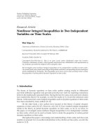
Figure 1: Steps of EDD calculation from ICT values.
A node’s EDD is equal to the minimum achievable delay,
or the delay through the quickest known node, given by.
edd
(
v
)
= min
c∈V
v
{d
(
v, c
)
}. (2)
In practice, this means CHARON uses a transitive delay
metric with an additive concatenation operator and an extra
variable per-hop factor. As a consequence, EDD is only
defined for nodes with a complete chain of contacts ending in
a sink. It is easier to visualize this by representing the network
as a graph, seen in Figure 1. Graph nodes correspond to
network nodes, and are marked with their EDD, while edges
correspond to “known node” relationships and are marked
with the recorded ICT. A node’s EDD is given by its shortest
path weight to the virtual sink, representing all real sinks.
A problem with this approach is that ICTs do not degrade
naturally, that is, if two nodes (a, b
⊂ V)donotmeet,
their ICT value stays unchanged. This may have serious
consequences if b is a’s best known forwarder and stops
being a good forwarder, perhaps because its movement
pattern changed or simply because it ran out of energy. As a’s
EDD also remains unchanged, it is advertising itself to be a
better forwarder than it is, potentially degrading the entire
network’s performance. We avoid the problem by taking into
account the difference between the recorded ICT and the
time elapsed since the last contact, replacing (1)with
d
(
v, c
)
= edd
(
c
)
+ict
(
v, c
)
+ictVar
(
v, c
)
H
(
ictVar
(
v, c
))
,
c
∈ V
v
,
(3)
ictVar
(
v, c
)
=
(
time
− lastContact
(
v, c
))
− ict
(
v, c
)
. (4)
The ICT variation function (4) is p ositive if the time since
last contact is in excess of the stored ICT value, and negative
otherwise. In (3), H refers to the Heaviside step function, as
only positive variation values should be considered.
Generally, messages are forwarded when a node with
lower EDD is met. Although other factors may be taken into
account when deciding whether to forward messages, a node
with higher EDD is never considered a suitable forwarder,
not only to minimize latency and energy waste but also as
a way to prevent loops created by rapid variation of other
metrics. The ICT of a link is an intermediate value, used only
to determine a node’s own EDD and not to make forwarding
decisions—at that point, nodes will already be in contact,
and the ICT is irrelevant.
3.2. Multivariate Utility Function. The concept of multifac-
tor utility functions has been used before in opportunistic
routing protocols, for example, [11]. The general idea is
that it is possible to get a better solution by taking more
information into account, which is normally true. There
is another equally important advantage, in that it allows
easy customization of the algorithm to the specific usage
setting. For instance, in an underwater WSN equipped with
barometric sensors, the pressure read is related to each
sensor’s depth. If messages are to be routed to the surface,
a lower pressure may indicate a good forwarder.
The use of utility functions in CHARON is optional. An
implementation can choose to use an empty utility function
(i.e., one that returns a constant value), basing the decision
only on the delay metric. If a utility function is defined, its
results (the score) should increase with the desirability of
the forwarder. In the case of EDD, on the contrary, lower
is better—it is a negative indicator. As such, its symmetric
should be used in the score’s calculation. A basic utility
function, using commonly available data, is (5). While the
EDD allows us to determine the quickest path, the free buffer
space is useful in preventing short-term buffer exhaustion
of the intermediate nodes. Finally, the use of battery level
serves to extend the lifetime of very desirable carriers, by
gradually moving the load to other nodes as they start
6 EURASIP Journal on Wireless Communications and Networking
A
1
2
3
4
56
Sink
(a)
8
9
10
11
12
Sink
A
1
2
3
4
5
6
7
(b)
Sink
A
1
2
3
4
5
6
7
(c)
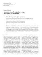
Figure 2: Different replication strategies (single copy, multi-copy and hybrid).
running out of energy
S
(
v
)
=−edd
(
v
)
+batteryLevel
(
v
)
+freeBuffer
(
v
)
. (5)
Depending on the expected EDD values and the range of
the other parameters, they may have to be individually scaled
in order to exert the desired influence on the final score.
Note that, as there is a separate safeguard against forwarding
messages to nodes with higher EDD, it is possible to build
utility functions that do not use the EDD. Those functions
are, however, replacing a possibly quantitative e valuation of
the EDD (“is the other node’s EDD so much better that it
compensates for our larger energy reserve?”) with a purely
binary assessment.
There are no significant restrictions to the utility function
other than having to return an integer value. They can be
as simple as or simpler than (5), return a single value or a
combination of several, or they can employ more advanced
logic: anything that can be expressed in the language used for
its implementation. Nevertheless, the use of simple functions
is recommended to keep up with the stated goals.
3.3. Message Replication. There are two main replication
strategies in widespread use. On the one hand, there are
single-copy solutions, in which only one copy of each
message is present in the network at any single time.
On the other hand, there are multi copy solutions that
replicate messages in network, resulting in the presence
of several redundant copies. Single-copy strategies achieve
high efficiency at the cost of reduced reliability; multi-copy
strategies take the opposite approach.
Having efficiency as a goal, a mostly single-copy
approach was chosen, with an additional optimization. In a
traditional single-copy approach, a node forwards a message
and subsequently erases it from its buffer. However, keeping
an already held message bears no cost, neither in bandwidth
nor in energy. As there is no real reason to remove such
messages, they are kept in a special state: the y are called
zombies. Zombies are leftover copies from previously carried
messages and cannot be forwarded. They are kept while
possible, and delivered only on the event that a node meets a
sink, after which they are erased.
This solution creates a hybrid strategy, combining the
advantages of single-copy schemes with some of the per-
formance improvements made possible by multi-copy ones.
A small comparison of the three strategies can be seen in
Figure 2.
(i) In the single-copy approach (a), the message flows
through the network and is delivered, just once, to
the sink. A message carried by a node that fails or
wanders away is lost.
(ii) In the multi-copy approach (b), the message is
copied at each carrier node, and then forwarded. This
results in an increase of the number of transmissions,
as well as in the amount of buffer space in use.
The number of paths being followed, as well as
the number of simultaneous carriers, does, however
increase delivery probability, which is reflected in the
number of copies (three) delivered to the sink.
(iii) In the hybrid approach (c), the message flows
through the same path, but nodes on that path
keep a zombie copy of the message. If any of these
nodes come in contact with the sink, they deliver the
message themselves. The problem is expressed in the
following example: after forwarding a message (5),
a node fi nds the sink, transmitting the zombie (7),
thereby providing resilience against failures further
down the path. While it is not the case in the example
figure, it is possible that a zombie copy reaches the
sink before the current holder of the message, in
which case delivery latency is also reduced.
Zombies have negligible impact on routing efficiency
(adding at most a single transmission per message), yet they
share the same properties of message copies in that they
increase fault tolerance and improve delivery statistics. They
EURASIP Journal on Wireless Communications and Networking 7
Table 1: Example class configuration.
Class Utility function Replication strategy TTL value
Monitoring S (c)= − edd (c)+freeBuffer (c)+batteryLevel (c) Hybrid 72 h
Alarm S(c)
=0 Multicopy 12 h
do, h owever, take up buffer space: a zombie message, being
a complete copy of its parent message, naturally requires
the same amount of memory. The fundamental difference
between a zombie and a copy comes into play when a node
runs out of memory:
(i) In a naive multi-copy strategy, a node has no way of
knowing whether it can delete a message in case it
runs out of memory. As this is a distributed problem,
there are no guarantees that all nodes will not delete
the same message, making it undeliverable.
(ii) In the hybrid strategy, nodes generally carry some
messages and some zombies. They know any zombie
can be safely removed, as its parent message is being
carried by some other node. Conversely, they know
they must not delete their messages, because no other
node carries them.
Despite the advantages of this approach, there are situa-
tions in which delivery probability must be maximized and,
perhaps most importantly, latency needs to be minimized
at any cost. The system supports a secondary purely multi-
copy mode for use in such situations. In this mode CHARON
does not tag forwarded messages as zombies, continuing to
forward them as before. While this mode does succeed in
improving delivery statistics, it has a negative impact on the
network as a whole if abused, and should only be employed
when strictly required.
3.4. QoS Classes. Even within specific applications, there are
sometimes messages with different requirements. A simple
example is that of an agricultural monitoring WSN: while
most messages probably contain only temperature, humidity
and PH samples and are not urgent, there can also be
alarm messages alerting the operators to a pest or a fire
threatening production and requiring immediate attention.
This coexistence of different requirements within the same
network is the motivation for including quality-of-service
(QoS) mechanisms in CHARON. Note, however, that the
definition of QoS in this context is limited to the ability to
provide different performance levels to different data classes.
Resource reservation and service level guarantees are difficult
(if not impossible) to implement in the target scenario and
within the stated goals, and as such were not considered.
In that sense, the service CHARON provides is always best-
effort.
The customizability of some parts of CHARON was
previously discussed, in what refers to the particularities
of the deployment scenario. The system is even more
adaptable as it can be customized for individual traffic classes
within the same deployment. There are three independently
configurable class-specific features: an utility function, a
replication strategy, and time-to-live (TTL) value.
Depending on the chosen settings, the result can range
from purely delay-based, multicopy routing with high over-
head but low latency to very efficient, single-copy, energy-
aware routing. While CHARON supports an unlimited
number of classes, in the vast majority of cases two will be
sufficient:
(i) A low-priority class used for bulk monitoring data,
configured with an energy-aware utility function and
hybrid replication
(ii) A high-priority class used for urgent alarm data,
configured with no utility function and multicopy
replication.
An example of such an arrangement is presented in
Table 1,wheredifferent TTL values were also defined. The
choice of TTL par ameters should take into account the
period during which data is useful. Alarm data is, by
definition, urgent and—considering the wasteful mechanism
being used to route it—should be set to expire as soon as
possible.
Using this simple scheme, CHARON is able to provide
multicopy-like performance on high-priority messages, as
long as they a re few and far in between, while still keeping
global overhead at very low levels. Evidently, this is only true
if alarm messages account for a small fraction of the total, or
global performance will be severely degraded.
3.5. Time Synchronization. There are two main ways to
obtain a global time reference on a WSN: listening to a
broadcast source, such as GPS or FM signals, or running
a synchronization protocol. While the former option is
simpler and more precise, it requires additional hardware.
Consequently, we decided to use a synchronization protocol.
There are already several high-precision time synchro-
nization protocols designed for WSNs [14]. Most were
designed for stationary networks and do not support oppor-
tunistic scenarios. The few that do, tend to behave poorly
under high mobility and/or be of high complexity. They also
introduce additional communication overhead in the form
of synchronization messages.
Since CHARON’s use for a time reference does not
require high precision, a simpler solution may be used. The
basic developed mechanism uses two fields on the periodic
beacons broadcast by each node, and allows synchronization
to the sinks’ clock. When a beacon is received, a node
updates its local reference using the algorithm presented in
Algorithm 2.
Sink nodes have an age of 0, and are always used as
sources. The stepPenalty parameter is indented to reduce
the number of average synchronization steps, as there is an
additional error introduced with each.
8 EURASIP Journal on Wireless Communications and Networking
algorithm update time (c) is
if localTimeAge
≥ timeAge(c) +stepPenalty then
localTime
← time(c)
localTimeAge
← timeAge(c) + stepPenalty
end
end
Algorithm 2: Time synchronization algorithm.
The algorithm is about as simple as can be. There is no
statistical treatment of time samples and t ransmission and
reception delays are not compensated for. While accuracy of
advanced algorithms can be in the order of microseconds, in
this case it is around tens of milliseconds. Seeing that there is
also no drift correction, the error will tend to rapidly increase
with reference age. Current digital clocks can, however,
maintain a useful reference for many hours or even days,
which is good enough for most scenarios. Implementations
should nevertheless monitor the age of the reference and
move the system back to an unsynchronized state if it exceeds
a given threshold, based on the used clocks’ specified drift.
In addition to being used for power management, the
global time reference is used to timestamp messages in a way
that allows them to be sorted and correlated at the sink. This
timestamp is also used to sort messages in the buffers and
check for TTL expiration. Finally, it can be queried and used
directly by applications.
3.6. Power Management. Regardless of how high an algo-
rithm’s routing efficiency is, it can not achieve good energy
efficiency per se. Broadband radios are not only one of the
largestconsumersbutcanuseasmuchorevenmoreenergy
on idle listening than they do while transmitting. To save
energy, this must be taken into account by turning off the
radio when it is not necessary.
There are several possible radio power management
approaches including synchronous [15] and asynchronous
[16, 17] cycling, as well as more advanced, on-demand
solutionssuchaswakeupradios[18]. Asynchronous cycling
presents a suboptimal solution, requiring very short rounds
that may inhibit advanced power saving modes, and can lead
to long always-on periods if trying to transmit in the absence
of neighbours. The use of wake-up radios is promising but
requires additional hardware on most current platforms.
This leaves synchronous cycling, which is generally a good
solution although it requires a global time reference. The
reference can either be provided by the CHARON-integrated
synchronization mechanism or any other available source.
The global clock is used to generate synchronous rounds
on all nodes. Rounds comprise an on time, when the radio
is turned on and communication takes place, and an off
time, when the radio is turned off and all system activity
is suspended. Although only radio power management is
handled, turning the radio off can ( depending on the
platform) allow the system to enter low-power modes,
further reducing energy consumption. For that to happen,
the applications must also be synchronized and suspend their
activities during off times, which is why we allow applications
to subscribe to round generation events.
There are two parameters controlling radio rounds: the
round period and the round time. The first describes the time
between successive round starts, while the second describes
the time the radio is left on in each round. The starting time
of the following round (τ) is computed from the current time
τ
=
(
time
\ roundPeriod + 1
)
∗ roundPeriod. (6)
The node must wake up frequently enough not to
miss too many connection opportunities and stay awake
long enough to hear the neighbour ing nodes’ beacons and
possibly forward messages. This requires some thought and
analysis during the definition of sleeping periods, as these
must be tailored to the scenario and take into account the
expected movement speed and radio range. We expected that
in most scenarios radios can be turned on for a few seconds
every minute, leading to dut y cycles around 10%.
When a node does not yet have a time reference available,
synchronized radio cycling is impossible. We have decided
not to implement a power-saving fallback mode, instead
keeping the radio permanently on until a reference is
acquired. While this might be seen as wasteful, in most
cases nodes can be initially synchronized at the time of
deployment, limiting the problem’s severity.
3.7. Reference Implementation. In order t o perform real-
world testing and validation of CHARON, we have devel-
oped a reference implementation, for which we used
Sun Microsystems’ Small Programmable Object Technology
(SPOT) [19] sensor nodes. These are relatively powerful
nodes, featuring an ARM9 processor, 512 Kilobyte of RAM,
4 Megabyte of Flash memory and an 802.15.4-compliant
CC2420 radio. Like most WSN nodes, they get their power
from a battery, and ship with a sensor board containing a 3-
axis accelerometer, temperature and light sensors, as well as
LEDs, switches and several input and output pins. Instead
of an operating system, the SPOT runs a bare-metal Java
VM-Squawk [20]. CHARON is implemented a s a bundle
layer, sitting atop the included network stack and using
the bundled datagram-based protocol (Radiogram) for all
single-hop exchanges.
As a side effect, this implementation allowed us to assess
the difficulty of deploying our solution in a real WSN,
which we found very acceptable. The full implementation
contains 32 classes and 1517 physical source lines of code
(SLOC), excluding utilities and debugging functionality. The
compiled suite stands at 47 KB, a value that, given the
system’s available memory, is barely noticeable.
4. Evaluation of Ro uting Performance
Opportunistic routing techniques are typical ly designed to be
used in large mobile networks—conditions w h ich are hard
to reproduce in a laboratory. Simulation techniques were
therefore used to evaluate the macroscopic behaviour of the
algorithm, in conditions resembling the target scenario.
EURASIP Journal on Wireless Communications and Networking 9
Simulations were performed using the Opportunistic
Network Environment (ONE) simulator [21], an open-
source Java-based simulator designed for evaluation of DTN
routing algorithms. As the reference implementation was
also written in Java, this option allowed for an easier
conversion. Furthermore, it includes implementations of
several algorithms that were used for comparison.
4.1. Base Scenario. Settings for the simulation were extracted
from the target scenario we previously described. The area
of movement was defined to be 80 km
2
,inordertoprovide
sufficient freedom of movement. A total of 60 nodes are
initially distributed randomly throughout the area, resulting
in a low node density of 0.75 nodes/km
2
,asexpectedfor
our target scenario. A single static sink is placed in the
centre of the map. We chose not to use multiple sinks, as
not all protocols evaluated support this kind of setup. For
an analysis of the impact of the number of sinks on the
performance of an opportunistic routing solution, we refer
the reader to [22].
There are six node groups, emulating a setting where
different spe cies or populations cohabit and exhibit different
behaviour. Each group has a set of predefined waypoints,
from which nodes select their next destination. Movement
speed is randomly chosen from a predefined range (1.8 km/h
to 18 km/h). Upon reaching a waypoint, nodes stop for
a random length of time (0 s to 120 s). Nodes of some
groups can never come in direct contact with the sink, as
their movement area does not include the centre of the
map. In the simulator used, this model of waypoint pools
is not compatible with unrestricted movement. Instead, an
approximation was implemented, in which n odes move on a
tight lattice of possible paths, using a shortest path algorithm
to reach their destination.
Each node generates fixed-size messages (200 B of raw
physical layer data) with fixed p eriodicity (60 s). All nodes
have 200 kB of buffer space, a reasonable size for current
memory capacities. All messages have the sink as their
destination. A single sink was used to allow fair comparison
to protocols that don not support more than one. Radio
range (40 m) and bitrate (250 kbit/s) were chosen to reflect
typical values for 802.15.4 [23] r adios used in WSNs.
Each simulation runs for a p eriod of 1 simulation day,
during which 1440 messages are generated. Movement and
event generation are regulated by a pseudorandom number
generator. The generator seed is the same for multiple
settings within each run, guaranteeing comparable results.
Table 2 presents a summary of the already listed simu-
lation parameters. These default parameters are used in al l
simulations, except where otherwise noted.
Several of the simulation parameters may seem excessive
namely, the message periodicity and the movement speed.
These were chosen in order to guarantee meaningful results
in simulations as short as 1 day, as the (real) time required
to run longer simulations was unbearable. To further reduce
variance and prevent artefacts caused by irregular movement,
all results are averaged from multiple runs with different
seeds.
Table 2: Default simulation parameters.
Area 80 km
2
Number of nodes 60
Run duration 1 d
Radio range 40 m
Radio bit rate 250 kbit/s
Buffer space 200 kB
Movement speed 1.8 km/h to 18 km/h
Idle movement time 0 s to 120 s
Message generation interval 60 s
Message size 200 B
Number of nodes
50
60
70
80
90
100
0 120 240 360 480
Synchronized nodes (%)
Time (minutes)
12
24
36
48
60
72
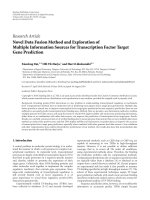
Figure 3: Evolution of network connectivity/synchronization dur-
ing the startup phase.
4.2. Startup Phase. The calculation of our routing metric for
a given node depends on the existence of a complete path
between it and a sink. Hence, there is a startup phase in which
nodes are not able to forward messages. During this period,
nodes don’t yet have a global time reference either; they are
in an unsynchronized state. Since the system is designed for
long-term deployments, this does not have a relevant impact
on the network performance. Nevertheless, the transitory
stage is interesting, and so we have measured the time to
full network synchronization in our reference scenario for
different number of nodes, with the results being presented
in Figure 3.
Despite the size of our scenario and the constraints on
node mobility, it can be seen that the time to ful l network
synchronization is, even for the worst case, in the range
of hours, confirming our assumption that, at least for this
scenario, the duration of the start-up phase is not relevant.
The results also show a clear dependence on the number of
nodes, due to its effect on contact density and on the number
of alternate paths.
It is also worth noting that, as expected, it generally takes
longer to synchronize the last 20% of nodes than all the
others. These are the nodes located farther away from the
sink, and that require more communication hops and/or
longer movement distances to reach it.
10 EURASIP Journal on Wireless Communications and Networking
0.4
0.5
0.6
0.7
0.8
0 100 200 300
Delivery ratio
Network load (messages/node/hour)
Single
Hybrid
(a)
Single
Hybrid
180
240
300
360
420
0 100 200 300
Average latency (minutes)
Network load (messages/node/hour)
(b)
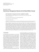
Figure 4: Performance impact of zombie messages.
120
180
240
300
1357
Average latency (minutes)
Network load (alarms/node/hour)
No QoS
QoS-overall
QoS-alarm
QoS-sensing
(a)
1357
Network load (alarms/node/hour)
No QoS
QoS-overall
QoS-alarm
QoS-sensing
0
10
20
30
40
50
60
Average overhead
(b)
Figure 5: Perfor mance impact of QoS mechanisms.
4.3. Replication Strateg y. The hybrid replication strategy
used in CHARON is based on the assumption that leaving
previously carried messages as zombies is better than deleting
them. To verify that assumption, the same simulation was
carried out comparing a pure single-copy strategy and
the proposed hybrid strategy. The simulation’s results are
presented in Figure 4.
As the network load increases, buffers start to fill up
and messages are dropped or are not forwarded in a useful
timeframe, leading to a decreased delivery ratio. Latency also
shows a slightly downward trend with increasing network
load, as when buffers are full, messages generated closer to
the sink are more likely to be delivered.
Results show a very significant improvement on delivery
statistics for the hybrid strategy, although the difference tends
to be smaller for higher loads, when zombies start being
deleted to make room for other messages. The results support
our assertion that, by using zombies and increasing the
number of alternative paths, delivery ratio and latency are
improved.
4.4. Quality of Service. QoS mechanisms also need to be
assessed in their ability to provide coexisting differentiated
service levels. To do so, a set of simulations were run in which
nodes generated sensing messages (at the normal rate of 60
messages per hour) and alarms (at a variable rate, leading to
different alarm/message ratios). Figure 5 presents the results
in several series:
(i) with QoS disabled, “No QoS”,
(ii) with QoS enabled
(a) alarm messages, “QoS-Alarm”,
(b) sensing messages, “QoS-Sensing”,
(c) overall outcome (alarm and sensing messages),
“QoS-Overall”.
The fi rst aspect to note is that the lines for non-QoS
traffic and sensing traffic mostly overlap, showing that in
this load range, high-priority trafficdoesnotnegatively
affect other traffic. Furthermore, alarm messages show a
clear improvement in their latency, reduced by more than
40%. These improvements come at a cost of higher specific
overhead (in line with multicopy approaches), yet global
overhead remains low. This relationship holds for any
scenario, as long as alarm messages make up for a small
fraction of the total.
EURASIP Journal on Wireless Communications and Networking 11
0.4
0.5
0.6
0.7
0.8
0.9
1
0 100
200 300
Delivery ratio
Network load (messages/node/hour)
(a)
0 100
200 300
Network load (messages/node/hour)
60
120
180
240
300
360
Average latency (minutes)
(b)
CHARON
Direct delivery
Epidemic
PROPHET
Spray and wait
0 100 200 300
Network load (messages/node/hour)
1
10
100
1000
Average overhead
(c)
CHARON
Direct delivery
Epidemic
PROPHET
Spray and wait
0 100
200 300
Network load (messages/node/hour)
0
1
2
3
4
5
6
Average hop c ount
(d)
Figure 6: Performance comparison for various network loads.
4.5. Comparative Assessment. To be meaningful, the results
obtained by CHARON must be compared to those attained
by other routing solutions. To enable this comparison,
we ran the same set of simulations using CHARON,
spray and wait [8], epidemic routing [7], PROPHET [10],
and direct delivery [24]. epidemic routing and PROPHET
are multicopy protocols, and therefore we expect them
to provide better results at lower loads. Spray and Wait
is technically a multicopy protocol, but with a bounded
number of copies per message (4 in this case), resulting in
an intermediate solution, and the closest to CHARON—for
that reason, it is generally not to be included when we refer
to multicopy protocols below. Finally, direct delivery is the
simplest possible single-copy protocol, allowing only direct
transmission, when the source meets the destination. For
fairness, neither CHARON nor any of the other protocols
were highly tuned for this specific scenario.
The simulation compares algor ithms’ performance for a
wide range of network loads, and its results are presented in
Figure 6.
Multicopy protocols behave better under low loads,
resulting in very high delivery probabilities with low latency.
As load increases, specifically around 90 messages per hour,
resources turn out to be scarce and the situation is reversed,
with CHARON and spray and wait taking the lead. With
these two protocols and direct delivery there is little variation
of delivery ratio with network load, due to the efficient use
of resources. The massive difference in terms of efficiency
can be seen on (c), wh ere PROPHET’s overhead is up to
70 times higher than CHARON’s. Latency is one of the
strong points of multicopy protocols, with a sustained lead
at every load. Differences in the latency a nd hop count
trends—decreasing with network load for CHARON, but
increasing for PROPHET and epidemic routing—are related
to the different message dropping schemes: CHARON drops
messages according to their global age (those generated
farther away tend to be dropped first), while in the others
they are dropped according to the order of reception
(regardless of when they were generated).
It is interesting to compare these results with the
ones obtained in the previous section. Under the exact
same scenario, the alarm class on a QoS-enabled instance
of CHARON can achieve delivery ratios above 0.80 and
latencies in the order of 160 minutes, in line with those
displayed by the best performers in the test. This means
CHARON can provide top-quality service to messages that
require it, while maintaining low general overhead.
Some conclusions c an be drawn about each protocol’s
performance relative to CHARON’s:
(i) Direct delivery consistently obtains the weakest
results, and is presented mostly as a baseline. Given
that, in the base scenario, only some nodes are capa-
ble of reaching the sink, there is a preset limitation on
the achievable delivery ratio; in a scenario w ith free
movement it could perform better. It is, nevertheless,
the most efficient protocol, having no overhead.
12 EURASIP Journal on Wireless Communications and Networking
Sink BA
Figure 7: Synchronization test scenario.
(ii) Spray and wait outperforms CHARON in many
of the shared design goals. It is a very simple
protocol, which achieves good results with low
overhead. Its performance is nevertheless linked to
the network diameter: in networks with different
mobility patterns, in which the minimum number
of hops required to reach the sink is greater, its
performance-to-overhead ratio tends to degrade.
This is not necessarily an obstacle to its use in real-
world deployments, as many scenarios do feature
rather low network diameter. On the other hand, it is
more resilient than CHARON to changing network
conditions and patternless movement, seeing as it
does not make use of historic data.
(iii) Epidemic routing and PROPHET show outstanding
performance at low network loads, although the
delivery ratio degrades quickly. They have an entirely
different focus, and the high overhead makes them
incompatible with the goals defined for CHARON.
(iv) CHARON fulfils its objective of good delivery statis-
tics with very low overhead. Delivery ratio is high, in
line with spray and wait’s and what realistically can
be expected from a single copy protocol, although
latency is somewhat high as well. The use of zombies
seems to have limited impact under these conditions,
as node movement is limited to separate areas,
reducing the probability of a past carrier finding
the sink. The QoS mechanism can make up for
this handicap in case urgent messages need to be
transferred, without a significant impact on the
overall efficiency.
5. Evaluation of Additional Features
Contrary to routing, which is hard to evaluate on a real-
world test bed, some of the algorithm features can only
be meaningfully evaluated when running in real hardware.
Using the previously mentioned reference implementation,
we have per formed some experiments meant to assess the
performance of the time synchronization and power man-
agement mechanisms. These experiments, and the results
obtained, are presented in this section.
5.1. Time Synchronization. To evaluate time synchronization
error, a simple application was developed. Upon reception
of a beacon, this application obtains the current global time
from CHARON and sends it back to the sink. By having two
nodes listen for beacons and comparing the timestamps each
returns, it is possible to determine the pairwise clock offset.
Figure 7 shows the test bed setup.
−0.1
0
0.1
0.2
0.3
0.4
0.5
0.6
−4 −3 −2 −101234
Probability density
Offset (ms)
Figure 8: Pairwise clock offset distribution.
Table 3: Pairwise synchronization offset.
Offset (ms)
εs
0,02 2,90
Table 4: Node lifetime under different power management config-
urations.
η 100% 70% 40% 10%
Lifetime (h) 14,63 18,00 28,35 79,71
Improvement — +23% +94% +445%
Direct comparisons against the sink’s reference are not
possible, as there is a nondeterministic delay between the
time when a beacon is delivered to the sink’s stack and the
moment it is ready for processing at the nodes. The beacon
does however reach all nodes at the same time (propagation
delays are negligible at workbench distances), and under
light loads is available for processing at approximately the
same time. Nevertheless, the technique does introduce some
measurement error.
The first experiment ran for one hour, with a one-second
beacon period, resulting in 3600 samples. The resulting offset
average (
ε) and standard deviation are presented in Table 3.
The measured offsets are acceptable for most uses, as is
the maximum absolute offset (22 ms). Figure 8 shows the
detailed offset distribution which naturally approaches a
normal distribution.
5.2. Power Management. The influence of CHARON’s radio
power management solution on the node lifetime was
measured by having a single fully charged node run the test
application while in permanent range of a sink. The s ink
recorded the arrival timestamp of every message, and the
lifetime was extracted by subtracting the first from the last
timestamps. The round period was set to 20 seconds and
the round time was var ied to achieve the duty cycles (η)
presented in Table 4.
The use of radio power management has a clear effect on
the global energy consumption. Not only is the radio turned
off but, given that the entire library and the application itself
are synchronized to the rounds, nodes are free to enter deep
sleep mode. While a SPOT node in a fully active state has a
EURASIP Journal on Wireless Communications and Networking 13
BSink A
Figure 9: Round time test scenario.
current drain of up to 104 mA, in deep sleep it is reduced
to just 33 μA, an almost negligible value [25]. In previous
experiments no strong connection was found between the
position the node occupies and its energy consumption. This
is justified by the fact that in the SPOT platform, energy
consumption is lower in transmit mode than in receive
mode [26], in which every node—regardless of its position—
spends the majority of time. For this reason, and considering
the long time required for each experiment, no tests were run
with multiple nodes.
Turning off the radio does, however, car ry an impact
on network performance. To assess that impact, another
experimental setup was created, and is shown in Figure 9.
A node w as installed on a rotating arm, w ith one other
node and a base station placed on opposite ends of its circle
of movement. The transmission power of the static nodes
was tuned so that communication was only possible with
the rotating node, and at very short distance. Therefore,
this node a cts as the single carrier, and features periodic
movement.
A full rotation takes approximately 13 seconds to com-
plete, given the motor speed used for the rotating arm and
the CHARON round t ime was set to 1 second, in order to
allow some flexibility in the definition of the round period.
This leads to much faster mobility conditions than those
expected for the target scenario, but still provides valuable
results. Tests were run for different round periods, each
lasting until 120 packets were received.
Looking at the results (presented in Figure 10)several
conclusions can be drawn.
(i) First, and as a general trend, one can see that
longer round periods lead to longer delays, which is
intuitive, as more contact opportunities are lost due
to the radio being off.
(ii) There is a steep increase in delay when the round
period is increased from 5 to 10 seconds. With 5
second rounds, most rotations result in contacts,
even if short, as that loosely fits the time the carrier
spends in range of each node. When using longer
periods, useless rotations become more frequent and
the network performance takes a hit.
(iii) When the round period is increased from 10 to 20
seconds, the average delay unexpectedly decreases.
This illustrates a risk with the use of rounds in
periodic movement situation: when the round period
loosely fits the movement period (or a submultiple of
it), we run the risk of synchronizing them in a way
that prevents communication for long intervals.
10
20
30
40
50
60
70
0 5 10 15 20
Average delay (s)
Roundperiod(s)
Figure 10: Average delivery delay for different round periods.
MN3 SN2 BSMN1SN4
5m 5m
BAC
SLDL DRSR
Tram-L
Tram-R
SPOT
Telos
Figure 11: Test bed plan.
6. Experimental Characterization
So far, we have presented a detailed description of CHARON
opportunistic approach and assessed its routing efficiency
through simulation results. In this section, we extend and
enrich CHARON analysis by discussing its performance in
an experimental scenario involving real WSN nodes.
Beginning w ith the description of the network scenario
and the experimental test bed where the tests were per-
formed, we will now present a simple theoretical model
strictly correlated with the mobility pattern, and able to
predict the system performance. Based on this model, we
will analyse the system behaviour, in particular in terms of
message delivery delay, comparing the experimental evidence
with the predicted results.
6.1. Test Bed Description and Mobility Pattern. The PeRT Lab
open-space inside ISMB premises hosted the test bed utilized
to realize a partially mobile network of WSN nodes running
CHARON. The test bed plan is shown in Figure 11.
The network is composed of five SPOT nodes: four of
them are configured as message sources and potential carriers
while the fifth one plays the role of Base Station (BS) and is
connected to a PC for data logging.
The nodes deployment results in a linear-constrained
topology. Three nodes, that is, BS plus SN2 and SN4, where
SN stands for static node, are positioned as follows: BS on
the extreme right side, S N4 on the opposite extreme left
side, and SN2 approximately halfway between BS and SN4.
The remaining two nodes, called MN1 and MN2, are mobile
(M stands for mobile). Figure 12 shows part of the test bed,
including the tr ams and one of the ends.
In particular, MN1 moves between BS and SN2 while
MN3 does the same between SN2 and SN4. To this aim, two
LEGO Mindstorms NXT robots are attached to a hanging
14 EURASIP Journal on Wireless Communications and Networking
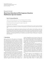
Figure 12: Photograph of the test bed, showing the two trams
approaching the center node (SN2), with SN4 and DL visible in the
background.
cable and behave as trams (indicated as Tram-R and Tram-L,
where R and L stand for right and left), endowing MN1 and
MN3 with mobility capabilities. As an approximation, speed
can be considered constant and equal for both trams. Minor
and negligible fluctuations sometimes could occur due to
the decay in battery level and the slightly different battery
capacity.
The mobility is quite symmetric and, above all, repetitive,
as a consequence of identical tram speed and internode
distances. In order to eliminate such periodicity and to let the
mobile nodes be in uncorrelated positions at a certain time
instant, the trams are programmed to stop for periods of
different duration. These stop periods occur after the trams’
front and rear ends, equipped with touch sensors, detect an
obstacle. In the case of Tram-R, the stopping period is set
to T
stop-R
= 5 seconds, and starts after hitting the obstacles
positioned near BS or SN2. Likewise, T
stop-L
= 3 seconds
holds for Tram-L whose stops are in proximity of SN2 and
SN4. After stopping, the tram resumes movement in the
opposite direction.
The physical distance between BS and SN2 (and between
SN2 and SN4) is around 5 metres. The transmission power
was tuned to guarantee that these pairs of nodes are always
out of the respective radio range and unable to directly
communicate. For this reason, the sequence of carrier nodes
that messages pass through along their path towards BS
is highly constrained, almost deterministic, despite node
mobility. Indeed, SN4 can solely forward messages to MN3,
and SN2 can relay through MN1 only. When coming
in contact with SN2, MN3 always finds it available as a
good relay; however, when the two trams approach SN2
at the same time, messages can sometimes be forwarded
directly from MN3 to MN1, skipping SN2 and gaining some
efficiency.
The test bed includes a simple channel quality moni-
toring tool. This tool basically consists of a pair of XBow
Telos nodes which exchange packets at high-frequency (in
the order of tenths of milliseconds) and allows us to derive
real-time information on link communication quality, based
on metrics like RSSI, LQI and lost, packets, while CHARON
is running on the SPOT nodes. We use that information
as input data for deeper interpretation and analysis of
CHARON dynamics, as detailed in the next subsection. In
our test bed, we have duplicated the tool, by deploying two
pairs of Telos. Concerning the first pair, one node has been
positioned near BS and the other on the tram next to MN1;
similarly, for the second pair, a node deployed near SN4 and
the other on the tram with MN3.
Since distinct computers are used to store data from
CHARON and from the monitoring tool, they have been
synchronized using NTP so that all events are time stamped
with a common reference. It is a lso worth noting that differ-
ent channels in the ISM 2.4 GHz frequency band have been
used for the CHARON nodes and for the monitoring tools,
in order to prevent mutual interference among applications.
On the other hand, the selected IEEE 802.15.4 channels, that
is, 24, 25, and 26, have been chosen to minimize the risk of
interference from Wi-Fi traffic[27].
6.2. Theoretical Analysis. We now introduce a simplified
mathematical model that will be used in the next subsection
for analysing experimental results obtained in the aforemen-
tioned test bed. The idea behind the model is to exploit the
symmetry of the network topology, the periodic mobility
pattern characterization and the resulting (almost) deter-
ministic paths followed by messages, to predict the network
behaviour on the longrun. The model equations derived
in the following require some input parameters, which are
estimated from the data collected by the monitoring tools.
6.2.1. Model Outputs Definition. The model provides the
expected probability density functions (pdf) of delays suf-
fered by messages from the moment they are generated
to the moment of final delivery to BS. These functions
are, respectively indicated as D
m
BS-MN1
, D
m
BS-SN2
, D
m
BS-MN3
,and
D
m
BS-SN4
, where the superscript m stands for model and the
notation in the subscript reports the last and the first node in
the path of interest.
6.2.2. Model Inputs Definition. The model takes as input
the following four quantities: T
trip-R
, T
trip-L
, T
c-R
and T
c-L
,
measured in seconds. Considering the repetitive mobility
pattern, T
trip-R
represents the time spent by Tram-R to
complete a trip. T
trip-L
has the same meaning, applied to
Tram-L. T
c-R
is the duration of the contact between MN1 and
BS or, equivalently, MN1 and SN2. A contact between two
nodes occurs when they are in mutual range, regardless of the
radio being on or off. An analogous definition holds for T
c-L
,
where the radio range concerns MN3 and SN2 or SN4. This
definition implicitly assumes that all nodes are considered to
have identical hardware (radio) features and that the radio
EURASIP Journal on Wireless Communications and Networking 15
Table 5: Summary of model inputs and output.
D
m
BS-i
Predicted end-to-end delivery delay for messages generated by node i
T
trip-x
Time taken by tram x to complete a trip
T
c-R
Duration of MN1’s contacts
T
c-L
Duration of MN3’s contacts
R Round period
propagation model is time invariant and depends only on the
distance between transmitter and receiver.
6.2.3. Model Inputs Estimation. In general, the above quan-
tities can b e different from trip to trip due to many
external factors; the variability is nevertheless expected
to be negligible. In addition, real contact periods cannot
be measured through direct observation. For our model
purpose, we derive an estimation of the model inputs by first
building a sample per trip and then averaging over all trips
logged during the test bed session.
The duration of a single trip can be empirically calculated
by processing the data collected by the monitoring tool; for
this, the fast dynamics of the Telos application fit better than
CHARON’s. In particular, we need to identify special events
that occur regularly once per trip and measure the inter-
event period. In this way, an estimation of both T
trip-R
and
T
trip-L
is achieved.
T
c-L
can be derived through the following formula: T
c-L
=
T
stop-L
+ T
c-R
− T
stop-R
, which requires that first we obtain an
estimation of T
c-R
. SPOT logs are the only useful data source
in this case because, despite both platforms being equipped
with the same CC2420 radio chip, the actual transmission
range is invariably different, even after manual tuning of the
transmission power. Measuring a contact period is made a
bit harder by the round-oriented operation of CHARON.
Indeed, the passage through the border of the radio coverage
area (in both directions) usually occurs while nodes are
in the off period and there is no way to know precisely
the time elapsed since the last transition of the functioning
mode. Nonetheless, a weighted average of the number of
sequential interactions during a contact allows us to build a
reliable estimation provided that the number of trips is large
enough.
6.2.4. Model Basic Assumptions. Thefinalgoalistodeter-
mine an analytical description for D
m
BS-MN1
, D
m
BS-SN2
, D
m
BS-MN3
and D
m
BS-SN4
, as a function of the quantities T
trip-R
, T
trip-L
,
T
c-R
and T
c-L
. To reach this goal we need to make some
simplifying assumptions so that the resulting model deriva-
tion is mathematically tractable. It is worth noting that such
assumptions generally lead to optimistic model predictions.
We consider unlimited storing space for messages, which
are therefore never deleted, and no communication failures
at the application level. We assume that a single interaction
during a contact is always sufficient to forward all the
messages currently stored by the carrier node while, in
general, the real behaviour depends on some CHARON
parameters, for example, the TLL or the maximum memory
space devoted to data storage. In fact, we will see from our
experiment that multiple interactions often occur, even when
they are not expected. Finally, message transfer delays, as
well as the time spent in completing other tasks like beacon
transmission or reception, are neglected. As a consequence,
multiples of R are the only admissible values for delivery
delays.
6.2.5. Model Outputs Derivation. As observed before, the
effective routes followed by messages targeted to BS are very
constrained, almost deterministic, due to the deployment’s
linear topology, the transmission power preventing com-
munication among static nodes, and the mobility pattern.
Definitively, this scenario facilitates the model development
since the delay characterization of messages originated by
a certain node can be exploited to derive the analogous
characterization for a farther node.
Suppose that MN1’s position and movement direction
at the start of a new round are known. Since messages
generated by MN1 never pass through intermediate carriers,
the delivery delay is deterministic. It can be computed
considering the distance covered by Tram-R to enter the
radio coverage area of BS (and, consequently, the time spent
to that aim) and, if this happens while the radio is off,
summing up the remaining time before it is turned on.
MN1’s initial position can be probabilistically characterized
as the mobility pattern of Tram-R is fully known: it
results in a uniform component due to the constant speed,
superimposed to two Dirac deltas justified by the stops near
BS and SN2. D
m
BS-MN1
can thus be finally determined. In
particular, it is intuitive to guess that null delay is experienced
if MN1 is inside BS coverage area when the round starts,
while maximum delay o ccurs when the contact with BS has
just finished. The rest of the delay distribution is uniform,
reflecting the mobility at constant speed. A summary of
the parameters can be found in Table 5, and the complete
characterisation of D
m
BS-MN1
is reported in Table 6 together
with D
m
BS-SN2
.
Messages from SN2 always follow the same route, going
through MN1, because SN2 is outside BS’s radio range.
The delay is minimized when MN1 is just on the border
of SN2’s coverage area, but still able to receive data from
SN2, and is moving towards BS when a new round starts.
We need to consider the time required to come in range
of BS and, possibly, the residual time before the next on
period starts. Maximum delay is determined in identical
conditions, with the difference that SN2 and MN1 have just
ended their communication window, so that an additional
complete trip is required. Again, the tram’s constant speed
guarantees uniform distribution elsewhere.
16 EURASIP Journal on Wireless Communications and Networking
Table 6: Characterisation of delivery delays for nodes MN1 and SN2. K is the largest integer such that the (T
c-R
+K·R)/T
trip-R
≤ 1, K
1
=
|
(T
trip-R
− 2 · T
c−R
)/2|
+
/R and K
2
+1=|T
trip-R
+(T
trip-R
− 2 · T
c−R
)/2|
+
/R, with |X|
+
representing the smallest integer larger than X.
D
m
BS-MN1
D
m
BS-SN2
Delay Probability Delay Probability
0 T
c-R
/T
trip-R
K
1
·R[K
1
·R-(T
trip-R
−2·T
c-R
)/2]/T
trip-R
i·RR/T
trip-R
, i = 1, ,K i·RR/T
trip-R
, i = K
1
+1, ,K
2
(K+1)·R1− (K · R+T
c-R
)/T
trip-R
(K
2
+1)·R1− [K
2
·R-(T
trip-R
−2·T
c-R
)/2]/T
trip-R
Things are more complex when considering D
m
BS-MN3
and D
m
BS-SN4
, because messages generated by MN3 or SN4
sometimes have two alternative routes after MN3: while
passing through SN2 is always possible, directly jumping
to MN1 represents a shortest and more efficient path
which is admissible only if the distance between MN3
and MN1 is smaller than the coverage radius when nodes
wake up and the message is generated. However, from our
model perspective, the assumption of instantaneous message
transfers guarantees that such an event can be managed as
if the message passes transparently through SN2, without
incurring additional delay. We can restrict our analysis only
to routes including SN2 without any loss of generality.
Another fundamental observation concerns the statistical
independence between the position of MN1 at a random
sampling time t and the position of MN3 position at the
same time, regardless their initial positions. Note that this is
true if t is taken over an infinite time period and is explained
by the different stopping times T
stop-R
and T
stop-L
.Inlight
of this, we can claim that D
m
BS-MN3
= D
m
BS-SN2
∗ D
m
SN2-MN3
and D
m
BS-SN4
= D
m
BS-SN2
∗ D
m
SN2-SN4
, where “∗” denotes the
convolution operation. To conclude, the analy tical expres-
sion of D
m
SN2-MN3
and D
m
SN2-SN4
exactly coincides with D
m
BS-MN1
and D
m
BS-SN2
respectively, the only required modification
consisting of T
c-R
and T
trip-R
being replaced with T
c-L
and
T
trip-L
.
6.3. Performance Evaluation. Implemented on the five SPOT
nodes (BS, MN1, SN2, MN3, SN4) constituting our test bed,
CHARON was tested for approximately 90 minutes. That
duration represents a tradeoff between two opposing needs.
On the one hand, the number of samples collected (e.g.,
sdelivery delays experienced by messages) or estimated (e.g.,
the duration of tram trips and contact events) during the
experiment must be large enough to guarantee statistical
reliability to processed data. On the other hand, the decrease
of trams speed during the test, caused by unavoidable robot
battery discharging, must be severely limited in order to
keep as time unvarying as possible the estimations of the
subsequent durations of trip periods.
CHARON settings were as follows during the test. The
round time and the round period were, respectively, set equal
to 2 and 10 seconds, while nodes in on mode exchanged
beacons every 500 milliseconds. The two instances of channel
quality monitoring tools, running at the two sides of the test
bed, were launched with the tr ansmitter node sending a new
packet every 50 milliseconds.
−100
−80
−60
−40
−20
0
−100
−50
0
50
100
150
200
250
300
0 50 100 150 200 250
RSSI (dBm)
Delay (s)
Time (s)
MN1
SN2
MN3
SN4
RSSI
Figure 13: Detail of system events at BS, extracted from the test
log, showing delivery delay of messages generated by SPOT nodes
and RSSI of messages received by the channel quality monitoring
nodes.
A zoom including about four minutes of system evo-
lution is reported in Figure 13, where network events as
captured by BS and the monitoring tool on the right s ide
during three complete tram trips are displayed. As expected,
SPOT messages are delivered to BS when the exchange of
packets between the pair of Telos nodes is persistent and
the channel quality is the best, as witnessed by collected
RSSI values. However, while the time correlation between
CHARON and Telos events is evident, in this test SPOT
nodes seem to be charac terized by a shorter radio coverage,
as can be deduced by the very distant time instants in which
nodes belonging to the two different platforms start a new
interaction.
Figure 13 shows another and more important phe-
nomenon. During each contact with BS, MN1 always needs
more than one interaction (i.e., multiple rounds), typically
2 or 3, to succeed in delivering the messages it was storing.
This leads to two relevant comments. First, the estimation of
the contact duration T
c-R
is necessarily comprised between
20 and 30 seconds. Indeed, three interac tions cover a
contact period of at least 20 seconds, while in case of two
interactions the contact period cannot exceed 30 seconds.
This is coherent with T
c-R
= 23.7 seconds, as found
by processing SPOT logs. T
trip-R
and T
trip-L
were instead
estimated using Telos logs and the mean values resulted equal
to 78.4 and 67.4 seconds respectively. Secondly, differently
from what would be expected in light of current CHARON
settings and differently from model predictions on the basis
of the assumptions made, MN1 often concludes a contact
with BS with some messages still stored and not delivered.
EURASIP Journal on Wireless Communications and Networking 17
0
0.05
0.1
0.15
0.2
0.25
0.3
0 20 40 60 80 100 120 140 160
Delay (s)
D
e
BS-MN1
(a)
0
0.05
0.1
0.15
0.2
0.25
0.3
0 10203040506070
Delay (s)
D
m
BS-MN1
(b)
0
0.03
0.06
0.09
0.12
0.15
0 30 60 90 120 150 180 210 240 270
Delay (s)
D
e
BS-SN2
(c)
0
0.03
0.06
0.09
0.12
0.15
0 102030405060708090100110
Delay (s)
D
m
BS-SN2
(d)
0 30 60 90 120 150 180 210 240
270
Delay (s)
0
0.03
0.06
0.09
0.12
0.15
D
e
BS-MN3
(e)
0
0.03
0.06
0.09
0.12
0.15
0 20 40 60 80 100 120 140 160 180
Delay (s)
D
m
BS-MN3
(f)
0
30 60 90
120
150
180
210 240
270
300
Delay (s)
D
e
BS-SN4
0
0.03
0.06
0.09
0.12
0.15
(g)
0 20 40 60 80 100 120 140 160 180
200
Delay (s)
D
m
BS-SN4
0
0.03
0.06
0.09
0.12
0.15
(h)
Figure 14: Experimental and predicted end-to-end delivery delay pdf.
These messages require a new contact, and thus a new tram
trip, to find a new chance to be transferred. Looking at
Figure 13, this can be clearly seen in the second trip, when
no MN1-generated messages are delivered.
The fundamental metric on which our performance
evaluation of CHARON is based is the latency experienced
by messages, from their own generation time to the instant
when they are delivered to BS. Since CHARON nodes
are synchronized, and having the message generation and
message reception events both time stamped, such latencies
can be calculated for each packet using SPOT logs. Then,
delays can be aggregated on a per-node basis and probability
density functions of delays based on experimental data
can be built. They are denoted respectively as D
e
BS-MN1
,
D
e
BS-SN2
, D
e
BS-MN3
and D
e
BS-SN4
and are conceptually anal-
ogous to the correspondent functions analytically defined
through the model developed in the previous subsection.
The comparison of the theoretical pdf with the experi-
mental one can provide useful indications about system
performance, possible inefficiencies and potential improve-
ments.
The results obtained are displayed in Figure 14,com-
posed of a pair of side-by-side plots for each of the four
SPOT nodes (MN1, SN2, MN3 and SN4). As a general
comment, the shape of the pdf achieved through the model
is qualitatively similar to the shape of the twin pdf obtained
with experimental data. This represents a clear validation of
the theoretical model.
Experimental results for messages originated by MN1
show that the null latency is the minimum and also the one
that occurs more frequently. This is confirmed by the model
prediction as well as the approximately uniform probability
18 EURASIP Journal on Wireless Communications and Networking
distribution characterizing the delay values in the range
[10–50]. The model foresees maximum theoretical delays
of 60 seconds, while larger delays are actually experienced
by a few messages. This means that such messages are not
delivered during the first useful contact b etween MN1 and
BS, in contrast with the model assumption and with the
expected application behaviour. More precisely, about one
message over five (0.219 is the weight of the distribution tail
comprising larger latencies than 60 seconds) requires at least
an additional trip of the tram before being delivered. We
can subtract to these delay samples multiples of 60 seconds,
caused by additional trips, thus spreading the unexpected
tail of D
e
BS-MN1
over the theoretical range [0–60]. Then,
by comparing the modified D
e
BS-MN1
(not plotted) with
D
m
BS-MN1
, the coherence between experiments and model is
further improved, as can be shown by the probability of
null delay or, for instance, by the sum of the least squares,
a common comparison metric, which decreases from 0.0224
to 0.0092.
Similar comments concern messages from SN2, since in
that case only Tram-R is involved. The discrepancy regarding
the minimum delivery delay (30 seconds by experimental
observations, 20 seconds according to the model) is fore-
seeable and coherent with the knowledge that the model
provides optimistic predictions.
The most significant a posteriori evidence when analyzing
delivery delay densities of messages generated by MN3 and
SN4 is that we were correct in postulating the statistical
independence between the positions of the two trams at
a random time, which the model derivation is explicitly
based on. In fact, the tr iangular shape, which charac terizes
both the experimental and the theoretical curves, is the
typical result of the convolution of two independent and uni-
formly distributed random variables. Since delivery delays
of messages originated by MN3 and SN4 are built over the
delays of nearer nodes MN1 and/or SN2, and since they
are consequently obtained as sum of independent contribu-
tions, whose estimations suffer from unavoidable errors, the
difference between minimum (or, equivalently, maximum)
delays under experimental and theoretical analysis tends to
increase. If other nodes were similarly deployed farther than
SN4 along the linear chain, the effect would be still more
evident, resulting proportional to the distance from BS, in
terms of intermediate carriers. Quantitative values are also
coherent: minimum delivery delays achieved through the
experimental session are equal to 30 and 60 seconds for
MN3 and SN4 respectively, compliant with 0 and 30 seconds
observed for MN1 and SN2.
Finally, we observe that the weight of the tails of
experimental pdf decreases as the number of intermediate
carriers grows, being respectively equal to 0.219, 0.254, 0.120
and 0.092 for MN1, SN2, MN3 and SN4. Indeed, when
considering nodes with several intermediate carriers along
the path to BS, worst-case events, that is, largest message
delivery delays, are experienced if worst-case less probable
events simultaneously occur at each intermediate hop.
To conclude, the main system dynamics are well captured
by the model and the minor discrepancies are easily justified
by the simplifying assumptions, often leading to optimistic
predictions. One of the most impacting , in light of the
experimental evidence, is the network load, in combination
with the number of messages that can be held in intermediate
buffers. We deduce this by the many events in which the time
necessary to forward or definitively deliver all messages in the
current round is not enough. Besides, it is worth remember-
ing that possible losses of communication opportunities due
to missed beacons or nondeterministic processing delays are
not taken into account by the theoretical model.
7. Conclusions and Future Work
We have described the development and evaluation of an
opportunistic solution for low-density WSNs, which we
called CHARON. This approach is focused on reliability,
simplicity, efficiency, and flexibility; more importantly, it
aims not only for theoretical performance, but also real-
world applicability. It is primarily built a round a routing
algorithm, but also includes additional atypical features.
Messages are routed by CHARON based primarily on the
expected delivery delay, combined with information about
the available resources or application-specific routing aids.
A hybrid replication st rategy is used for most messages to
minimize resource waste. It works in a way similar to a single-
copy strategy, but taking advantage of zombies, the inevitable
copies left behind. Several uncommon features are also
built-in to CHARON. Basic quality-of-service support makes
it possible to serve coexisting applications with different
needs. A time synchronization solution allows a global low-
precision time reference to be shared by every node, and
enables the use of synchronous radio power management,
which can reduce energy waste, increasing node lifetime by
up to 440% for a 10% duty cycle.
CHARON achieves better delivery statistics for high
network loads than multicopy algorithms, with delivery ratio
never falling below 0.65 in our simulation scenario. Its
overhead is up to 100 times lower than that of the multicopy
algorithms, resulting in a performance-to-overhead ratio
up to 80 times better. While for light loads its results are
below those achieved by multicopy algorithms, the overhead
is still much lower. For urgent data, the built-in QoS
mechanism can still provide multicopy-like performance,
with the inevitable higher overhead. We also show that our
hybrid replication strategy leads to significantly increased
delivery statistics with minimal drawbacks.
Furthermore, we have performed advanced real-world
evaluation of the developed solution, and compared the
results obtained with those of a simple theoretical framework
that has been shown to be able to predict the system’s per-
formance under some simplifying assumptions. Specifically,
the model is able to predict the shape of the delivery delay
pdf, although it has some bias towards the lower delays,
explained by some optimistic assumptions, namely the one
that bandwidth is unlimited and all buffered messages can
be delivered in a single contact. Seeing as the model fi ts
reality, it may be used to predict the solution’s performance
under different operating conditions, so long as the mobility
patterns share some similarity.
EURASIP Journal on Wireless Communications and Networking 19
Interesting topics for future research include the use of
message integrity codes to provide trusted forwarding and
the extraction of approximate location information from a
node’s history of contacts, assuming static nodes are present
and georeferenced. The synchronization mechanism could
be improved by taking into account more than just the
freshest reference, making it more resilient. Lastly, more
advanced treatment of delay metrics should be investigated.
Nevertheless, improvements have a tendency to increase
complexity, and a cautious cost-benefit analysis should be
made. Finally, we would like to test the system under real
operating conditions (e.g., in a silvopastoral monitoring
WSN) in order to identify any practical weaknesses in the
solution.
Acknowledgments
We would like to thank our colleagues at both the Group of
Embedded networked Systems and Heterogeneous Networks
(GEMS), Laboratory of Excellence in Mobility (LEMe),
Instituto Superior T
´
ecnico and the Pervasive Radio Tech-
nologies Lab (PeRT), Istituto Superiore Mario Boella for
all the help during the development and evaluation of this
work. The blind reviewers of this paper also deserve our
gratitude, for the many suggestions for improvement they
provided us with. This work was sponsored by Instituto de
Telecomunicac¸
˜
oes and Instituto Superior T
´
ecnico, Technical
University of Lisbon, and Istituto Superiore Mario Boella. It
was partly supported by the European Commission through
the FP7 Network of Excellence in Wireless Communications
NEWCOM++ (Contract no. 216715), and results of a joint
work within the Experimental Activities Joint Research
Activity of WPR.11.
References
[1] J. Yick, B. Mukherjee, and D. Ghosal, “Wireless sensor network
survey,” Computer Networks, vol. 52, no. 12, pp. 2292–2330,
2008.
[2] L. Pelusi, A. Passarella, and M. Conti, “Opportunistic net-
working: data forwarding in disconnected mobile ad hoc
networks,” IEEE Communications Magazine, vol. 44, no. 11,
pp. 134–141, 2006.
[3] P. Zhang, C. M. Sadler, S. A. Lyon, and M. Martonosi,
“Hardware design experiences in ZebraNet,” in Proceedings
of the 2nd International Conference on Embedded Networked
Sensor Systems (SenSys ’04), pp. 227–238, Baltimore, Md, USA,
2004.
[4] A. S. Tanenbaum, C. Gamage, and B. Crispo, “Taking sensor
networks from the lab to the jungle,” Computer, vol. 39, no. 8,
pp. 98–100, 2006.
[5] R. C. Shah, S. Roy, S. Jain, and W. Brunette, “Data MULEs:
modeling and analysis of a three-tier architecture for sparse
sensor networks,” in Proceedings of the 1st IEEE International
Workshop on Sensor Network Protocols and Applications,pp.
30–41, Anchorage, Alaska, USA, September 2003.
[6] J. M. Soares and R. M. Rocha, “CHARON: routing in low-
density opportunistic wireless sensor networks,” in Proceedings
of the 2nd IFIP Wireless Days (WD ’09), Paris, France, 2009.
[7] A. Vahdat and D. Becker, “Epidemic routing for partially-
connected ad hoc networks,” Tech. Rep. CS-2000-06, Duke
University, Durham, NC, USA, 2000.
[8] T. Spyropoulos, K. Psounis, and C. S. Raghavendra, “Spray
and wait: an efficient routing scheme for intermittently
connected mobile networks,” in Proceedings of the ACM
SIGCOMM Workshop on Delay-Tolerant Networking, pp. 252–
259, Philadelphia, Pa, USA, 2005.
[9] P. Juang, H. Oki, Y. Wang, M. Martonosi, L S. Peh, and D.
Rubenstein, “Energy-efficient computing for wildlife tracking:
design tradeoffs and early experiences with ZebraNet,” in Pro-
ceedings of the 10th International Conference on Architectural
Support for Programming Languages and Operating Systems,
pp. 96–107, San Jose, Calif, USA, October 2002.
[10] A. Lindgren, A. Doria, and O. Schel
´
en, “Probabilistic routing
in intermittently connected networks,” ACM SIGMOBILE
Mobile Computing and Communications Review, vol. 7, no. 3,
pp. 19–20, 2003.
[11] B. P
´
asztor, M. Musolesi, and C. Mascolo, “Opportunistic
mobile sensor data collection with SCAR,” in Proceedings of
the IEEE Internatonal Conference on Mobile Ad Hoc and Sensor
Systems (MASS ’07), pp. 1–12, Pisa, Italy, October 2007.
[12] M. Musolesi, S. Hailes, and C. Mascolo, “Adaptive routing
for intermittently connected mobile ad hoc networks,” in
Proceedings of the 6th IEEE International Symposium on a
World of Wireless Mobile and Multimedia Networks (WoWMoM
’05), pp. 183–189, Taormina-Giardini Naxos, Italy, 2005.
[13] R. Baumann, S. Heimlicher, M. Strasser, and A. Weibel, “A
survey on routing metrics,” TIK Report 262, ETH-Zentrum,
Zurich, Switzerland, 2007.
[14] B. Sundararaman, U. Buy, and A. D. Kshemkalyani, “Clock
synchronization for wireless sensor networks: a survey,” Ad
Hoc Networks, vol. 3, no. 3, pp. 281–323, 2005.
[15] J. M. Soares, B. Gonc¸alves, and R. Rocha, “Power management
extensions for tagus-sensornet,” in Proceedings of the 18th
International Conference on Computer Communications and
Networks (ICCCN ’09), San Francisco, Calif, USA, August
2009.
[16] A. El-Hoiydi and J D. D ecotignie, “WiseMAC: an ultra
low power MAC protocol for multi-hop wireless sensor
networks,” in Proceedings of the 9th International Symposium
on Computers and Communications (ISCC ’04), pp. 244–251,
Belfast, Northern Ireland, 2004.
[17] J. Polastre, J. Hill, and D. Culler, “Versatile low power media
access for wireless sensor networks,” in Proceedings of the
2nd International Conference on Embedded Networked Sensor
Systems (SenSys ’04), pp. 95–107, Baltimore, Md, USA, 2004.
[18] L. Gu and J. A. Stankovic, “Radio-triggered wake-up for
wireless sensor networks,” Real-Time Systems, vol. 29, no. 2-
3, pp. 157–182, 2005.
[19] R. B. Smith, “SPOTWorld and the Sun SPOT,” in Proceedings
of the 6th International Symposium on Information Processing
in Sensor Networks (IPSN ’07), pp. 565–566, Cambridge, Mass,
USA, April 2007.
[20] D. Simon, C. Cifuentes, D. Cleal, J. Daniels, and D. White,
“Java
TM
on the bare metal of wireless sensor devices the
squawk java virtual machine,” in Proceedings of the 2nd
International Conference on Virtual Execution Environments
(VEE ’06), pp. 78–88, Ottawa, Canada, 2006.
[21] A. Ker
¨
anen,J.Ott,andT.K
¨
arkk
¨
ainen, “The ONE simulator
for DTN protocol evaluation,” in Proceedings of the 2nd
International Conference on Simulation Tools and Techniques
(SIMUTools ’09), Rome, Italy, 2009.
20 EURASIP Journal on Wireless Communications and Networking
[22] T. Small and Z. J. Haas, “The shared wireless infostation
model—a new ad hoc networking paradigm (or where there
is a whale, there is a way),” in Proceedings of the 4th ACM
International Symposium on Mobile Ad Hoc Networking and
Computing (MobiHoc ’03), pp. 233–244, Annapolis, Md, USA,
2003.
[23] “IEEE Standard 802.15.4: Wireless Medium Access Control
(MAC) and Physical Layer (PHY) Specifications for Low-
Rate Wireless Personal Area Networks (WPANs),” IEEE, Std
802.15.4-2006, 2006.
[24] T. Matsuda and T. Takine, “(p,q)-epidemic routing for sparsely
populated mobile ad hoc networks,” IEEE Journal on Selected
Areas in Communications, vol. 26, no. 5, Article ID 4530735,
pp. 783–793, 2008.
[25] Sun Labs, “Sun SPOT Owner’s Manual—Red Release 5.0,”
2009.
[26] Chipcon, “CC2420—2.4 GHz IEEE 802.15.4 / ZigBee-ready
RF Transceiver,” Datasheet SWRS041, 2006.
[27] H. Khaleel, C. Pastrone, F. Penna, M. A. Spirito, and R. Garello,
“ImpactofWi-Fitraffic on the IEEE 802.15.4 channels
occupation in indoor environments,” in Proceedings of the 11th
IEEE International Conference on Electromagnetics in Advanced
Applications (ICEAA ’09), pp. 1042–1045, Turin, Italy, 2009.