Recent Optical and Photonic Technologies Part 1 doc
Bạn đang xem bản rút gọn của tài liệu. Xem và tải ngay bản đầy đủ của tài liệu tại đây (2.3 MB, 30 trang )
Recent Optical and
Photonic Technologies
Recent Optical and
Photonic Technologies
Edited by
Ki Young Kim
Intech
IV
Published by Intech
Intech
Olajnica 19/2, 32000 Vukovar, Croatia
Abstracting and non-profit use of the material is permitted with credit to the source. Statements and
opinions expressed in the chapters are these of the individual contributors and not necessarily those of
the editors or publisher. No responsibility is accepted for the accuracy of information contained in the
published articles. Publisher assumes no responsibility liability for any damage or injury to persons or
property arising out of the use of any materials, instructions, methods or ideas contained inside. After
this work has been published by the Intech, authors have the right to republish it, in whole or part, in
any publication of which they are an author or editor, and the make other personal use of the work.
© 2010 Intech
Free online edition of this book you can find under www.sciyo.com
Additional copies can be obtained from:
First published January 2010
Printed in India
Technical Editor: Teodora Smiljanic
Recent Optical and Photonic Technologies, Edited by Ki Young Kim
p. cm.
ISBN 978-953-7619-71-8
Preface
Research and development in modern optical and photonic technologies have
witnessed quite fast growing advancements in various fundamental and application areas
due to availability of novel fabrication and measurement techniques, advanced numerical
simulation tools and methods, as well as due to the increasing practical demands. The recent
advancements have also been accompanied by the appearance of various interdisciplinary
topics.
The book attempts to put together state-of-the-art research and development in optical
and photonic technologies. It consists of 21 chapters that focus on interesting four topics of
photonic crystals (first 5 chapters), THz techniques and applications (next 7 chapters),
nanoscale optical techniques and applications (next 5 chapters), and optical trapping and
manipulation (last 4 chapters), in which a fundamental theory, numerical simulation
techniques, measurement techniques and methods, and various application examples are
considered.
This book concerns itself with recent and advanced research results and comprehensive
reviews on optical and photonic technologies covering the aforementioned topics. I believe
that the advanced techniques and research described here may also be applicable to other
contemporary research areas in optical and photonic technologies. Thus, I hope the readers
will be inspired to start or to improve further their own research and technologies and to
expand potential applications.
I would like to express my sincere gratitude to all the authors for their outstanding
contributions to this book.
January 2010
Editor
Ki Young Kim
Department of Physics
National Cheng Kung University
Tainan, Taiwan
E-mail:
Contents
Preface V
Photonic Crystals
1. Dual-Periodic Photonic Crystal Structures 001
Alexey Yamilov
and Mark Herrera
2. Two-Dimensional Photonic Crystal Micro-cavities
for Chip-scale Laser Applications
031
Adam Mock and Ling Lu
3. Anisotropy of Light Extraction Emission with High Polarization Ratio
from GaN-based Photonic Crystal Light-emitting Diodes
053
Chun-Feng Lai, Chia-Hsin Chao, and Hao-Chung Kuo
4. Holographic Fabrication of Three-Dimensional Woodpile-type
Photonic Crystal Templates Using Phase Mask Technique
071
Di Xu, Kevin P. Chen, Kris Ohlinger and Yuankun Lin
5. Quantum Electrodynamics in Photonic Crystal Nanocavities
towards Quantum Information Processing
089
Yun-Feng Xiao, Xu-Bo Zou, Qihuang Gong,
Guang-Can Guo, and Chee Wei Wong
THz Techniques and Applications
6. Terahertz-wave Parametric Sources 109
Shin’ichiro Hayashi and Kodo Kawase
7. Cherenkov Phase Matched Monochromatic Tunable
Terahertz Wave Generation
125
Koji Suizu, Takayuki Shibuya and Kodo Kawase
8. Nonreciprocal Phenomena on Reflection
of Terahertz Radiation off Antiferromagnets
143
T. Dumelow, J. A. P. da Costa, F. Lima and E. L. Albuquerque
VIII
9. Room Temperature Integrated Terahertz Emitters
based on Three-Wave Mixing in Semiconductor Microcylinders
169
A. Taormina, A. Andronico, F. Ghiglieno, S. Ducci, I. Favero and G. Leo
10. Terahertz Time-Domain Spectroscopy
of Metallic Particle Ensembles
187
Kenneth J. Chau
11. Applications of Tilted-Pulse-Front Excitation 207
József András Fülöp and János Hebling
12. Applications of Effective Medium Theories
in the Terahertz Regime
231
Maik Scheller, Christian Jansen, and Martin Koch
Nanoscale Optical Techniques and Applications
13. Local Electric Polarization Vector Detection 251
Kwang Geol Lee and DaiSik Kim
14. Nanoimprint Lithography - Next Generation Nanopatterning Methods
for Nanophotonics Fabrication
275
Jukka Viheriälä, Tapio Niemi, Juha Kontio and Markus Pessa
15. Nanoscale Photodetector Array and Its Application
to Near-Field Nano-Imaging
299
Boyang Liu, Ki Young Kim, and Seng-Tiong Ho
16. Spontaneous and Stimulated Transitions
in Impurity Dielectric Nanoparticles
317
K.K. Pukhov, Yu.V. Orlovskii and T.T. Basiev
17. Photon-Number-Resolution at Telecom Wavelength
with Superconducting Nanowires
341
Francesco Marsili, David Bitauld, Andrea Fiore,
Alessandro Gaggero, Francesco Mattioli, Roberto Leoni,
Aleksander Divochiy and Gregory Gol'tsman
Optical Trapping and Manipulation
18. Optoelectronic Tweezers for the Manipulation of Cells,
Microparticles, and Nanoparticles
367
Aaron T. Ohta, Pei-Yu Chiou, Arash Jamshidi, Hsan-Yin Hsu,
Justin K. Valley, Steven L. Neale, and Ming C. Wu
IX
19. An Asymmetric Magneto-Optical Trap 389
Heung-Ryoul Noh and Wonho Jhe
20. The Photonic Torque Microscope:
Measuring Non-conservative Force-fields
411
Giovanni Volpe, Giorgio Volpe and Giuseppe Pesce
21. Dynamics of a Kerr Nanoparticle in a Single Beam Optical Trap 435
Romeric Pobre and Caesar Saloma
Photonic Crystals
1
Dual-Periodic Photonic Crystal Structures
Alexey Yamilov
and Mark Herrera
1
Department of Physics, Missouri University of Science & Technology, Rolla, MO 65409,
U.S.A.
1. Introduction
In this chapter we discuss optical properties of dual-periodic photonic (super-)structures.
Conventional photonic crystal structures exhibit a periodic modulation of the dielectric
constant in one, two or three spatial dimensions (Joannopoulos, 2008). In a dual-periodic
structure, the dielectric constant is varied on two distinct scales a
1,2
along the same
direction(s). An example of such a variation is given by the expression:
0
12
22
()= 1 cos cos .xxx
aa
π
π
εε γ
⎛⎞
+Δ× + ×
⎜⎟
⎝⎠
(1)
In Sec. 2, after motivating our study, we describe one attractive possibility for a large-scale
fabrication of the dual-periodic structures such as in Eq. (1) using the interference photo-
lithorgraphy technique.
Sec. 3 presents the theory of slow-light effect in a dual-periodic photonic crystal. Here, four
numerical and analytical techniques employed to study optical properties of the system. In
the result, we obtain a physically transparent description based on the coupled-resonator
optical waveguide (CROW) concept (Yariv et al., 1999).
Sec. 4 is devoted to discussion of a new type of optical waveguides – trench waveguide – in
photonic crystal slabs. We demonstrate that this type of waveguide leads to an appearance
of a second (super-) modulation in the slab, thus, slow-light devices / coupled-cavity micro-
resonator arrays can be straightforwardly fabricated in the photonic crystal slab geometry.
Importantly, the fabrication of such structures also does not require slow (serial) electron-
beam lithography and can be accomplished with scalable (holographic) photolithography.
The chapter concludes with a discussion and an outlook.
2. Dual-periodic structure as a photonic super-crystal
Optical pulse propagation in dielectrics is determined by the group velocity v
g
= d
ω
(K)/dK,
where the dispersion
ω
(K) relates the frequency
ω
and the wave vector K inside the medium.
One of the appealing features of photonic crystals has become a possibility to alter the
dispersion of electromagnetic waves (Soukoulis, 1996) so that in a certain spectral region v
g
becomes significantly smaller than the speed of light in vacuum. This “slowlight” effect
(Milonni, 2005) attracted a great deal of practical interest because it can lead to low-
threshold lasing (Nojima, 1998; Sakoda, 1999; Susa, 2001), pulse delay(Poon et al., 2004;
1
Currently at department of Physics, University of Maryland
Recent Optical and Photonic Technologies
2
Vlasov et al., 2005), optical memories (Scheuer et al., 2005), and to enhanced nonlinear
interactions (Soljacic et al, 2002; Xu et al., 2000; Jacobsen et al., 2006). Several approaches to
obtaining low dispersion in photonic crystal structures have been exploited:
i. At frequencies close to the photonic band-edge,
ω
(K) becomes flat and group velocity
approaches zero due to the Bragg effect at the Brillouin zone boundary. This property
has been extensively studied and used in practice to control the spontaneous emission
(Yablonovitch, 1987) and gain enhancement in lasers (Nojima, 1998; Sakoda, 1999; Susa,
2001). However, a large second order dispersion (i.e. dependence of v
g
on frequency) in
the vicinity of the bandedge leads to strong distortions in a pulsed signal that makes
this approach unsuitable for, e.g., information processing applications.
ii. High order bands in two- and three-dimensional photonic crystals can have small
dispersion not only at the Brillouin zone boundary but also throughout the band
(Galisteo-López & López, 2004; Scharrer et al., 2006) where the second order dispersion
can be significantly reduced. Nevertheless, these high-frequency photonic bands allow
little control over v
g
and are not spectrally isolated from other bands. These drawbacks
and the increased sensitivity to fabrication errors (Dorado et al., 2007), limit the
practical value of this approach.
iii. Based on the Coupled Resonator Optical Waveguide idea (CROW)(Stefanou &
Modinos, 1998; Yariv et al., 1999; Poon et al., 2006; Scheuer et al., 2005), a low-dispersion
photonic band can be purposefully created via hybridization of high-Q resonances
arising from periodically positioned structural defects (Bayindir et al., 2001a;b; Altug &
Vuckovic, 2005; Olivier et al., 2001; Karle et al., 2002; Happ et al., 2003; Yanik & Fan,
2004). This spectrally isolated defect-band is formed inside the photonic bandgap, with a
dispersion relation given by
( ) = [1 cos( )].KKL
ωκ
Ω+ (2)
Here Ω is the resonance frequency for a single defect,
κ
is the coupling constant
(assumed to be small) and L is the spacing between defects. These adjustable
parameters allow one to control the dispersion in the band, and hence v
g
, without
significant detrimental effects associated with the second order dispersion.
A periodic arrangement of structural defects in the photonic crystal, described in (iii),
creates a dual-periodic photonic super-crystal (PhSC) with short-range quasi-periodicity on
the scale of the lattice constant and with long-range periodicity on the defect separation
scale (Shimada et al., 2001; Kitahara et al., 2004; Shimada et al., 1998; Liu et al., 2002; Sipe et
al., 1994; Benedickson et al., 1996; Bristow et al., 2003; Janner et al., 2005; Yagasaki et al.,
2006). These structures usually need to be constructed with the layer-by-layer technique (or,
more generally, serially) which is susceptible to the fabrication errors similarly to the other
approaches (i,ii) above. We have recently proposed a PhSC with dual-harmonic modulation
of the refractive index (Yamilov & Bertino, 2007), similar to Eq. (1), that can be fabricated by
e.g. a single-step interference photolithography technique (Bertino et al., 2004; 2007). We
considered four S-polarized laser beams defined by
11 0 1 1 1
22 0 2 2 2
11 0 1 1 1
22 0 2 2 2
, { sin( ),0,cos( )},
, { sin( ),0,cos( )},
.
, {sin( ),0,cos( )},
, {sin( ),0,cos( )},
LL
LL
RR
RR
Ek E
Ek E
Ek E
Ek E
θθ
θθ
θθ
θθ
−
⎡
⎤⎡ ⎤
⎢
⎥⎢ ⎥
−
⎢
⎥⎢ ⎥
=
⎢
⎥⎢ ⎥
⎢
⎥⎢ ⎥
⎢
⎥⎢ ⎥
⎣
⎦⎣ ⎦
q
q
q
q
(3)
Dual-Periodic Photonic Crystal Structures
3
Here q and E are the k-vector and amplitude of the beams respectively. Their interference
pattern E
tot
(x) ∝
α
cos(k
1
x) +
β
cos(k
2
x) leads to
2
2
012
()=()= cos( ) cos( )nx x kx kx
εεεα β
+Δ +
⎡
⎤
⎣
⎦
(4)
where k
1
− k
2
≡ Δk, (k
1
+ k
2
)/2 ≡ k and
+
β
= 1. k and Δk are related to the short (a
S
) and long
range modulations of the refractive index: a
S
= 2
π
/Δk, a
L
=
π
/k. The parameters in Eqs. (3, 4)
are related as
= E
1
/(E
1
+ E
2
),
β
= E
2
/(E
1
+ E
2
) and k
1
= k
0
sin
θ
1
, k
2
= k
0
sin
θ
2
. Manipulation of
the beams allows for an easy control over the structural properties of the resultant PhC: (i)
fundamental periodicity a
S
via k
0
and
θ
1,2
; (ii) long-range modulation a
L
via
θ
1
−
θ
2
; and (iii)
depth of the long-range modulation via relative intensity of the beams E
1
/E
2
. As we
demonstrate in Sec. 3, the longer range modulation accomplishes the goal of creating the
periodically positioned optical resonators. The condition of weak coupling
κ
1 between
the states of the neighboring resonators requires sufficiently large barriers and therefore
a
S
a
L
, which we assume hereafter. Our approach to making dual-periodic structures has
an advantage in that all resonators are produced at once and, therefore, it minimizes
fabrication error margin and ensures the large-scale periodicity essential for hybridization of
the resonances of individual cavities in an experiment.
Dual-periodic harmonic modulation of the refractive index can also be experimentally
realized in optically-induced photorefractive crystals (Fleischer et al., 2003; Neshev et al.,
2003; Efremidis et al., 2002). Although, the index contrast obtained is several orders of
magnitude less than with QDPL (Bertino et al., 2004; 2007), the superlattices created in
photorefractive materials offer a possibility of dynamical control – a feature lacking in the
quantum dot system. While the study of dynamical and nonlinear phenomena in dual-
periodic lattices is of significant interest, it goes beyond the scope of our study and will not
be considered in this work.
3. Theory of slow-light effect in dual-periodic photonic lattices
In this section we theoretically investigate the optical properties of a one-dimensional PhSC
using a combination of analytical and numerical techniques. We consider the dielectric
function of the form given in Eq. (1) that can be produced with the interference
photolithography method:
() ()
0
/2
( ) = 1 cos 2 / 1 cos 2 / .
1
xxLxa
ε
εε γ π π
γ
Δ
⎡
⎤⎡ ⎤
++ +
⎣
⎦⎣ ⎦
+
(5)
Here ε
0
is the background dielectric constant. The amplitude of the short-range (on scale a)
modulation gradually changes from Δε × (1 − γ)/(1 + γ) to Δε, c.f. Fig. 1a. L = Na sets the
scale of the long-range modulation, N 1 is an integer.
The functional form in Eq. (5) was chosen to enable an analytic treatment and differs slightly
from Eq. (4). Nonetheless, it shows the same spectral composition and modulation property.
The discrepancy between the two forms is expected to cause only small deviations from the
analytical results obtained in this section. Furthermore, the differences become insignificant
in the limit N 1.
Recent Optical and Photonic Technologies
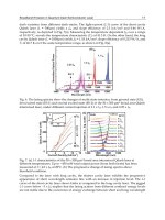
4
Fig. 1. (a) Dependence of the index of refraction in a dual-periodic photonic crystal as
defined by Eq. (5). We used ε
0
= 2.25, Δε = 1, N = 80 and the modulation parameter γ is equal
to 0.25. (b) Local (position-dependent) photonic bandgap diagramfor n(x) in (a).
()N
i
A and
()N
i
B
mark the frequencies of the foremost photonic bands on the long- and short-
wavelength sides of the photonic bandgap of the corresponding single-periodic crystal.
3.1 Transfer matrix analysis and coupled-resonators description of PhSC
The transmission/reflection spectrum of a one-dimensional PhSC of finite length, and the
band structure of its infinite counterpart can be obtained numerically via the transfer matrix
approach. Propagation of a field with wavevector
k =
ω
/c through an infinitesimal segment
of length dx is described by the transfer matrix (Yeh, 2005)
m
1
cos( ( ) ) ( )sin( ( ) )
(, )
()sin( () ) cos( () )
kn x dx n x kn x dx
Mxx xd
nx knxdx knxdx
−
⎡
⎤
+=
⎢
⎥
−
⎢
⎥
⎣
⎦
(6)
where we have assumed that the refractive index n(x) does not change appreciably over that
distance. The matrix
m
M
(x, x + dx) relates the electric field and its spatial derivative {E,1/k
dE/dx} at x + dx and x. The total transfer matrix of a finite system is then given by the
product of individual matrices
mm
0
(, ).
L
tot
x
M
Mxx dx
=
=+
∏
(7)
Since in our case the refractive index n(x) = ε
1/2
(x), Fig. 1(a), is not a piece-wise constant (in
contrast to Refs. (Sipe et al., 1994; Benedickson et al., 1996)) but rather a continuous function
of coordinate, one has to resort to numerical simulations. In what follows, we apply either
Dual-Periodic Photonic Crystal Structures
5
scattering or periodic boundary conditions to obtain the transmission coefficient and Bloch
number K(
ω
) respectively.
Figure 2(a) plots the transmission coefficient through one period of the dual-periodic system
shown in Fig. 1. A series of progressively sharper resonances occur on the lower or upper
edge of the spectral gap of the underlying single-periodic structure. Whether the peaks
occur at the lower or upper band edge depends on the particular definition of the unit cell,
as shown in the inset of Fig. 2(a). One can gain an insight into this effect by examining the
modulation of the spectral position of the “local” photonic bandgap (PBG) with the position
as shown in Fig. 1(b). This analysis is meaningful on the length scale of the order a
Δx
L ≡ Na. This condition can be satisfied in our case of slow modulation, with large N. At
frequencies such as
()N
i
A in Fig. 1(b), wave propagation is allowed in the vicinity of x = aN
×(1/2 +m), whereas at the regions x = aN × m, with m being an integer, it is locally
forbidden. When considering a segment of the lattice with 0 < x < Na, resonant tunneling via
electromagnetic states
()N
i
A
of the cavity at the geometrical center leads to low-frequency
peaks in the transmission coefficient, indicated by the solid line in Fig. 2(a). On the other
hand, transmission through the segment −Na/2 < x < Na/2 exhibits a series of sharp
resonances. These correspond to tunneling via
()N
i
B
cavity states in the high-frequency
region.
Fig. 2. (a) Transmission coefficient through a finite segment of length L (one period) of the
periodic super-structure defined in Fig. 1. Solid and dashed lines correspond to 0 < x < Na
and −Na/2 < x < Na/2 segments (shown in the inset of panel (b)) respectively. (b) Solid and
dashed thin lines plot the corresponding phase of t(
ω
). Bold line depicts the Bloch number
K(
ω
)× a of the infinite crystal computed using Eq. 8.
Recent Optical and Photonic Technologies
6
The transmission coefficient through a finite segment of length L (equal to one period) can
be related to the band structure of the corresponding periodic lattice (Benedickson et al.,
1996) as
11
cos( ( ) ) = [ ] cos( ( )),
() |()|
KLRe
tt
ω
φω
ωω
≡ (8)
where we have introduced the phase of the transmission coefficient
φ
(
ω
) through t =
|t|exp[i
φ
]. Fig. 3 shows that hybridization of the cavity resonances considered above leads
to the formation of flat photonic bands. Their low dispersion and small group velocity may
be exploited (Yamilov & Bertino, 2007) for practical applications.
In the vicinity of an isolated transmission resonance, t(
ω
) is given by the Lorentzian
0
(1)( /2)
()=
(/2)( )
N
t
i
ω
ω
ω
−Γ
Γ−−
(9)
where Γ is the full width at half maximum (FWHM) of the resonance and
ω
0
is the resonant
frequency. Substitution of Eq. 9 into Eq. 8 gives the flat band described by
0
()= [1 cos( )]KKL
ω
ωκ
±
(10)
where
0
1
== 1
2 Q
κ
ω
Γ
, and Q is the cavity Q-factor. Thus, the decrease of group velocity in
the PhSC is directly related to the increase of confinement and the decrease of coupling
between neighboring cavities. In our PhSC both these factors are described by the same
parameter – the cavity Q-factor. In a single-periodic photonic crystal of finite length, the Q-
factor of a band-edge mode depends on the system size. Comparing Fig. 1(b) and Fig. 3, one
can see that
()N
i
A ,
()N
i
B
modes are in fact band edge modes in their intervals of free
propagation.
In our case L gives the characteristic length and as we demonstrate below, also determines
the mode frequency. As N increases, the eigenfrequencies of the modes shift towards the
bandgap. The associated decrease of the local group velocity contributes to an increase of
the Q-factor of the resonators and to a further reduction of the group velocity in
()N
i
A
,
()N
i
B
bands in the
N →∞ limit.
Eq. (8) suggests that the dispersion relation
ω
(K) is independent of how the segment of
length
L (the period of our structure) is chosen. However, the transmission coefficient
through the 0 <
x < Na and −Na/2 < x < Na/2 segments of the crystal shows very different
spectral composition, Fig. 2(a). In order to understand how these markedly different
functions lead to the same
ω
(K), we analyze the phase of the transmission coefficient
φ
,
shown in Fig. 2(b).
In a one-dimensional periodic system such as ours, the wave number
K(
ω
) in Eq. 8 is equal
to the integrated density of electromagnetic states. It is, by definition, a monotonically
increasing function of frequency in the extended Brillouin zone scheme. In PhSC,
K × L
increases by
π
every time the frequency is increased through an allowed band, c.f. bold line
in Fig. 2(b). At the frequency in the middle of the band, cos(
KL) = 0 because K × L =
π
×
(
m + 1/2). From Eq. (8) one can see that
φ
should be equal to
π
× (m+1/2) at the same
frequency. In the finite system, the mode counting phase
φ
defined (Lifshitz et al., 1998) as
Dual-Periodic Photonic Crystal Structures
7
Fig. 3. The left panel shows dispersion of a PhSC
ω
(K) reduced to the first Brillouin zone.
The eigenmodes which correspond to the series of flat bands in the vicinity of the parent-
bandgap of the single periodic crystal are depicted on the right. Calculations were
performed for the structure described in Fig. 1.
tan(
φ
) = E′/E coincides with the phase of the transmission coefficient
φ
≡
φ
. This explains
the monotonic behavior of
φ
(
ω
). Eq. (8) leads to the fact that quasi-states of the finite system
occur at the same place as the corresponding band center of the lattice, irrespective of the
definition of the unit cell. Therefore, as can be also seen from Fig. 2(b),
φ
(
ω
) and K(
ω
)L
intersect at
π
× (m + 1/2).
Taylor expansion of the phase around the frequency
ω
0
at the center of a pass band, where
K(
ω
)L =
π
× (m + 1/2) gives
0
0
0
(1) ( )
cos( ( ) ) =( ) .
()
m
d
KL
td
φ
ω
ωωω
ωω
−
−×
(11)
Here, the term that contained
d |t(
ω
0
)|/d
ω
dropped out because cos(K(
ω
0
)L) = 0.
Comparing Eqs. (10) and (11) shows that it is |
t(
ω
0
)|
−1
d
φ
(
ω
0
)/d
ω
that determines Q =
1/
κ
and not just |t(
ω
0
)|. Suppressed transmission compensates for a slow phase change
(e.g. solid line in Fig. 2(b) in the high frequency spectral region) and leads to an identical
K(
ω
) for two different definitions of the unit cell.
We also note that if the segment is chosen such that the corresponding “cavity” is located in
the geometrical center (|
t(
ω
0
)| = 1), the FWHM of the resonance (Γ) in the transmission
Recent Optical and Photonic Technologies
8
coefficient is equal to the width of the pass band in the periodic lattice. This fact follows
from Eqs. (8) and (9). It further emphasizes the analogy with CROW structures.
We conclude this section by reiterating that long-range refractive index modulation creates
alternating spatial regions which serve as resonators separated by the tunneling barriers.
Hybridization of the cavity resonances creates a series of photonic bands with low
dispersion. The envelope of the eigenstates in these bands
()N
i
A ,
()N
i
B
is a slowly varying
function of the coordinate, c.f. Fig. 3. This effect stems from states proximity to the photonic
band-edge of the underlying single-periodic lattice. The possibility of a separation into short
(
a of rapid field oscillations) and long (L of the slow amplitude variation) length scales will
further inform analytical studies presented in the following sections.
In addition, the results of this section lead to somewhat counter-intuitive conclusion that the
larger or even complete modulation in Eq. (5) would negatively affect (increase) the
coupling between the resonators. This can also be seen from PBG diagram in Fig. 1b: in case
of compete modulation of the refractive index (
γ
= 1), the local bandgap disappears at x
m
=
aN × (1/2+ m). Indeed, our photonic band structure calculations demonstrate that structures
with 100% modulation are less advantageous and lead to significantly larger propagation
speeds. The optimum value of
γ
depends on the experimental parameters (ε
0
, Δε
and N) and
should be determined with the help of PBG diagram similar to Fig. 1b. The diagram also
proves useful in explaining the advantage of
A
N
over B
N
. In the latter case, the tunneling
barriers are thinner and their localization length is longer (PBG is spectrally narrower at
x
m
= aN × (1/2 + m) than it is at x
m
= aN × m).
3.2 Resonant approximation
Forbidden gaps in the spectra of a periodic system arise due to a resonant interaction of the
wave with its Bragg-scattered counterpart (Ashcroft & Mermin, 1976). The scattered wave
appears due to the presence of Fourier harmonics in the spectrum of the periodic
“potential”, which in the case of the Helmholtz equation
22
22
() ()()= (),Ex xEx Ex
cc
ωω
δε ε
′′
+
(12)
is represented by
22 22
(/)()(/)()cx cx
ω
δε ω ε ε
≡
−
⎡
⎤
⎣
⎦
. Here we have introduced the average
value of the dielectric function
0
=()= /[2(1 )]x
ε
εεε γ
+Δ +
. When γ = 0, the condition
/1
ε
ε
Δ
is sufficient to obtain the position and width of spectral gaps. Otherwise, an
additional condition N
× /1
ε
ε
Δ
needs to be satisfied instead. We will discuss the
physical meaning of this condition at the end of this section.
We begin by noticing that
ε(x) of our choice (Eq. 5) contains only eight nonzero Fourier
harmonics:
=
2
()= exp ,
m
m
ximx
L
π
εε
∞
−∞
⎡
⎤
⎢
⎥
⎣
⎦
∑
(13)
where m = {±1,±(N − 1),±N,±(N + 1))}. This fact allows for an exhaustive study of all resonant
interactions as follows. Expressing E(x) in terms of its Fourier components
Dual-Periodic Photonic Crystal Structures
9
=
2
()=exp[ ()] exp
m
m
Ex iK x E i mx
L
π
ω
∞
−∞
⎡
⎤
⎢
⎥
⎣
⎦
∑
(14)
leads to an infinite system of linear coupled equations
2
22
''
22
'0
2
() =0,
mmmm
m
KmE E
cLc
ωπω
εω ε
−
≠
⎡⎤
⎛⎞
−+ +
⎢⎥
⎜⎟
⎝⎠
⎢⎥
⎣⎦
∑
(15)
where K is the Bloch number that varies in the first Brillouin zone [0,
π
/L]. For the extreme
values of K there exists a spectral range where the term in brackets in Eq. 15 can become
simultaneously small for certain values of m and −m at K = 0, and for m and −m − 1 at
K =
π
/L. If ε(x) contains a harmonic ε
m
′
such that it couples these two Fourier components,
the overall infinite system Eq. 15 can be reduced to two resonant equations.
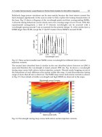
Fig. 4. Dispersion relation computed with the transfer matrix formalism for ε
0
= 2.25,
Δε
= 0.32, N = 9 (dashed line) and N = 10 (solid line). The modulation parameter γ
is equal to
0.25. For this set of parameters, the applicability condition Eq. 16 of the resonant
approximation is satisfied.
The results of such an analysis are summarized in Table 1 and the corresponding band
structure is shown in Fig. 4. Introduction of the long range modulation in the dielectric
constant results in an expansion of the unit cell from a to L = Na and, thus, to a reduction of
the Brillouin zone, accompanied by the folding of photonic bands. The cases of even N = 2s
and odd N = 2s + 1 should be distinguished. In the former, the primary photonic bandgap
(II
e
) of the single-periodic lattice reappears at K = 0, whereas in the latter (II
o
) it is located at
Recent Optical and Photonic Technologies
10
K =
π
/L. Our analysis shows that the nearest frequency gaps, I
o,e
and III
o,e
, also become
resonant, Fig. 4. For the refractive index modulation of Eq. (5), the normalized width
(1)
/4
/=
1
N
γ
εε
εε
γ
−
Δ
+
of the satellite gaps is smaller than that of the central gap by a factor of
γ. By definition, this parameter is less than unity.
We can see that folding and the offset of the formation of flat
()
1
N
A ,
()
1
N
B bands is captured
in this approximation. The criterion of its applicability can be found by considering the
contributions of non resonant terms in Eq. (15). We find that for all three gaps the criteria are
qualitatively the same. Therefore, we present the detailed analysis of only one particular
resonance, III
e
. The condition that the closest non-resonant Fourier components E
−s−2
, E
−s
,
E
s−1
and E
s+1
be smaller than the resonant ones E
−s−1
and E
s
leads to the relation
2
1
2
1
(1)( )
1.
42(1)
N
N
N
NN
εε
εε
−
++
++
(16)
In the limit of very large N the second term in the denominator becomes dominant and this
condition cannot be satisfied for any value of Δε. Thus, N should be finite. The condition that
the first termin the denominator be dominant, is consistent with the entire inequality Eq.
(16), and is equivalent to
/1
i
N
ε
ε
.
Taking the most restrictive case for ε
i
, we finally obtain
1,
8
N
ε
ε
Δ
×
(17)
where we have neglected
γ
for simplicity.
Equation (17) has a clear physical meaning. Indeed, from Table 1, it is clear that the
frequency of bandgaps I and III approach the central gap inherited from the single periodic
system as 1/N. At some point, a bandgap of width Δ
ω
/
ω
0
= ε
i
/
ε
begins to substantially
perturb the pass band of width K
max
× c
ω
0
/N separating consecutive gaps. The resonant
approximation breaks when these two scales become comparable. This condition results in
Eq. (17). In other words, the approximation considered in this section can at most capture
the onset of the flattening trend in the
()
1
N
A ,
()
1
N
B
bands and fails when N is increased to the
point where these states become abnormally flat, i.e., where Δ
ω
/K
max
c/
ε
throughout the
band. More sophisticated approaches are considered below.
Table 1. Results of resonant approximation analysis of Eq. (15) with dielectric function given
by Eq. (5). Three columns correspond to the three resonant photonic band gaps that appear
in the spectrum of the dual-periodic PhSC. The expressions hold for both even and odd N
for the choice of parameter s: N = 2s and N = 2s + 1 respectively.
Dual-Periodic Photonic Crystal Structures
11
3.3 Effective medium approximation
Gratings written in the core of photosensitive optical fibers are often analyzed with the help
of coupled-mode theory (CMT) (Marcuse, 1991). In both shallow gratings with long-range
modulation in fibers (Sipe et al., 1994; Janner et al., 2005) and in our PhSC, the forward and
backward (locally) propagating waves continuously scatter into each other. The advantage
of CMT is that it considers the amplitudes of the forward and backward waves directly. This
tremendously simplifies Maxwell equations. Ref. (de Sterke, 1998) also considered fiber
gratings with a deep piece-wise constant index modulation. In this section we employ the
CMT-based method developed by Sipe, et al. (Sipe et al., 1994) to obtain the spectral
positions of the flat photonic bands formed in a PhSC.
For shallow modulation, i.e., small Δε, our Eq. (5) can be brought to resemble the model
function considered in Ref. (Sipe et al., 1994)
00
()/ =1 () 2()cos2 ()nx n x x kx x
σκ ϕ
++ +
⎡
⎤
⎣
⎦
(18)
with the following choice of parameters
0
/4
2
1
()= cos ;
/2
1
xx
L
γε
π
γ
σ
ε
ε
γ
Δ
+
×
Δ
+
+
0
/8
2
1
()= 1 cos ;
/2
1
xx
L
ε
π
γ
κγ
ε
ε
γ
Δ
⎛⎞
+
×+
⎜⎟
Δ
⎝⎠
+
+
(19)
1/2
00 0
/2
() 0; = ; = /.
1
xn ka
ε
ϕε π
γ
⎛⎞
Δ
≡+
⎜⎟
+
⎝⎠
The CMT of Ref. (Sipe et al., 1994) is applicable as long as these functions have
a slow
dependence on x
, on the scale much larger than
1
0
k
−
. This condition is indeed satisfied in the
PhSC with
N 1.
By introducing small detuning parameter
00
0
00
=1,=
kc
n
ωω
δω
ω
−
we can, following Ref. (Sipe et al., 1994), obtain the governing equation for the quantity
E
e f f
related to the envelope of the electric field
2
22
0
2
(, ) =0.
eff
eff eff
dE
kn x E
dx
ω
+
(20)
Frequency and position dependent effective refractive index
221/2
={( ( ) ) ( ) }
eff
nx x
σκ
+Δ −
(21)
determines whether propagation is locally allowed (real n
e f f
) or forbidden (imaginary n
e f f
).
This is similar to our definition of the local PBG diagram which we studied numerically in
Section 3. Figure 5b compares CMT’s region of evanescent propagation (solid lines) to the
Recent Optical and Photonic Technologies
12
numerical calculation (dashed lines). We attribute the relatively small discrepancy observed
there to the assumption of shallow modulation made in arriving at Eq. (21).
Eq. (20) is formally similar to the Schrödinger equation. Our previous analysis shows that
the single-period states associated with photonic bands
() ()
,
NN
ii
A
B
are confined to the region
of classically allowed propagation, in the language of quantum mechanics. By analogy, the
Wentzel-Kramers-Brillouin (WKB) approximation of quantum mechanics can be applied
(Sipe et al., 1994) to determine the quantization of energies inside our optical equivalent of a
quantum well
0
()= (,) =( 1/2)
x
R
eff
x
L
Iknxdxm
ω
ωπ
+
∫
(22)
in which
x
L
and x
R
are, respectively, the left and right turning points defined by the
condition
n
e f f
(x
L,R
,
ω
) = 0, m is an integer. The solid line in Fig. 5a depicts the value of the
integral in Eq. (22), as a function of
ω
, obtained numerically. The filled circles denote the
frequencies at which quantization condition Eq. (22) is satisfied. In a system with the
parameters which we used for illustration in previous sections, the obtained solutions are in
fair agreement with numerical results obtained with the transfer matrix approach described
in Section 3. This suggests that the index variation given by Δ
ε
= 1, ε
0
= 2.25 was sufficiently
small for this approach to still be qualitatively applicable.
Fig. 5. (a) The value of the integral in Eq. (22), solid line, as a function of frequency is shown.
For easy comparison with (b), the plot is transposed so that
ω
is plotted along the y-axis. The
circles depict frequencies that satisfy the quantization condition of Eq. (22). The dashed lines
denote the actual position of photonic states, as determined by direct numerical analysis of
Section 3. (b) Gray-scale plot of
Re[n
e f f
(x,
ω
)] given by Eq (21). The solid line shows the
boundary of the regionwhere
Im[n
e f f
(x,
ω
)] ≠ 0. For comparisonwe also show the local PBG
of Fig. 1(b), dashed line. In both (a) and (b), the parameters of Fig. 1 are adopted.
Dual-Periodic Photonic Crystal Structures
13
We finish the current section by noting that it would be desirable to retain the attractive
property of the CMT envelope approach without being constrained by the condition of
small refractive index modulation. The latter may not always be justified in the experimental
situation of interest (Bertino et al., 2004; 2007). In the following section we develop such an
approach.
3.4 Bogolyubov-Mitropolsky approach
In this section we will consider the standing-wave solutions of Eq. (12). In this case, the
corresponding
E(x) can be chosen to be a real function by an appropriate choice of
normalization. Then, we make the Bogolyubov anzatz (Landa, 2001; Bogolyubov &
Mitropolsky, 1974):
(
)
()
0
00
()= ()cos ()
()/ = ()sin (),
Ex Ax kx x
dE x dx k A x k x x
φ
φ
+
−+
(23)
where, as in the preceding section,
k
0
=
π
/a. The above equations define the amplitude and
phase functions. Their substitution into Eq. (15) gives the so-called Bogolyubov equations in
standard form (Landa, 2001; Bogolyubov & Mitropolsky, 1974)
()
()
2
2
2
00
2
0
2
2
00
2
0
() 1
=() ()
cos
() ()
=()sin2(),
2
dx
xk kx x
dx k c
dA x A x
xk kx x
dx k c
φω
εφ
ω
εφ
⎡⎤
−+
⎢⎥
⎣⎦
⎡⎤
−+
⎢⎥
⎣⎦
(24)
No approximations have been made so far. The structure of the above equation suggests
that conditions
dA/dx k
0
A and d
φ
/dx k
0
φ
can be satisfied in the vicinity of the spectral
region where
22 2
000
(1 / ) / ( )kcxkk
ωε
⎡⎤
−
⎣⎦
. Here, the overbar denotes an average over one
period. Comparison with the analysis in the previous sections shows that this condition is
satisfied in the vicinity of the primary photonic bandgap. In the system of interest, for which
N
1, this observation justifies the “averaging-out” of the fast spectral components, which is the
Mitropolsky technique (Bogolyubov & Mitropolsky, 1974). This averaging procedure leads to
the following system of nonlinear equations for the slow-varying amplitude and phase
22
2
00
22
0
() 1 /2 2 1
= 1 cos 1 cos2 ( )
21 2
dx
kxx
dx k c c L
φωωε π
εγφ
γ
⎡
⎤
Δ
⎛⎞⎛ ⎞
−+ + +
⎢
⎥
⎜⎟⎜ ⎟
+
⎝⎠⎝ ⎠
⎣
⎦
(25)
2
2
0
log ( )
1/2 2
=1cossin2().
21
dAx
xx
dx k c L
ωε π
γφ
γ
Δ
⎛⎞
+
⎜⎟
+
⎝⎠
(26)
In deriving Eqs. (25) and (26) we have used the explicit form of
ε(x) given by Eq. (5).
We begin the analysis of Eqs. (25) and (26) with a discussion of the appropriate boundary
conditions. In deriving these equations we have limited consideration to real-valued
solutions of the original Eq. (15), which can be found only for a discrete set of frequencies.
At these special frequencies, the corresponding amplitude function should reflect the
periodicity of the dielectric function Eq. (5). This implies that