Solid State Circuits Technologies Part 1 pot
Bạn đang xem bản rút gọn của tài liệu. Xem và tải ngay bản đầy đủ của tài liệu tại đây (1.26 MB, 30 trang )
Solid State Circuits Technologies
Solid State Circuits Technologies
Edited by
Jacobus W. Swart
Intech
IV
Published by Intech
Intech
Olajnica 19/2, 32000 Vukovar, Croatia
Abstracting and non-profit use of the material is permitted with credit to the source. Statements and
opinions expressed in the chapters are these of the individual contributors and not necessarily those of
the editors or publisher. No responsibility is accepted for the accuracy of information contained in the
published articles. Publisher assumes no responsibility liability for any damage or injury to persons or
property arising out of the use of any materials, instructions, methods or ideas contained inside. After
this work has been published by the Intech, authors have the right to republish it, in whole or part, in
any publication of which they are an author or editor, and the make other personal use of the work.
© 2010 Intech
Free online edition of this book you can find under www.sciyo.com
Additional copies can be obtained from:
First published January 2010
Printed in India
Technical Editor: Teodora Smiljanic
Solid State Circuits Technologies, Edited by Jacobus W. Swart
p. cm.
ISBN 978-953-307-045-2
Preface
The evolution of solid-state circuit technology has a long history within a relatively
short period of time. This technology has leaded to: the modern information society that
connects us and tools; a large market; and, many types of products and applications. The
solid-state circuit technology continuously evolves via breakthroughs and improvements
every year. This book is devoted to review and present novel approaches for some of the
main issues involved in this exciting and vigorous technology.
The book is composed of 22 chapters, written by authors coming from 30 different
institutions located in12 different countries throughout the Americas, Asia and Europe.
Thus, reflecting the wide international contribution to the book.
Low power consumption is becoming a paramount issue for modern integrated circuits,
motivated by the huge integration level of modern electronics. In addition, the need for
power-aware applications such as mobile electronics, RFIDs, implantable medical devices
and smart sensor network motivates the development of low power consumption hardware.
Circuit design techniques that aim for reduced power consumption are treated in the first
two chapters. Accurate device modeling is essential for IC design and the models are
constantly adapted to take into account smaller dimension effects. This subject is treated in
chapter 3, focusing on the saturation mechanisms. Thermal noise and process variations
affect the performance, yield and minimum bias voltage or power consumption of the
circuits. These issues are the subjects of chapters 6 to 8.
The new and future CMOS technologies with constantly decreasing dimensions require
new solutions to: reduce gate leakage; increase gate capacitance per area; reduce the sub-
threshold slope; and increase transconductance, among other issues. These solutions have
lead to new transistor structures, high-k dielectrics and metal gates. Critical technological
innovations covering these solutions are presented in chapters 7 to 9.
Interconnects represents another critical issue in IC technology. A large part of the total
die area is represented by interconnects having a large effect on the performance and
reliability of the circuits. Carbon nanotubes are considered a promising material for
interconnects. The modeling of interconnects as transmission lines and, in addition, the use
of inductive-coupling links between chips are considered. Chapters 11 to 15 cover such
important issues.
Microelectromechanical systems (MEMS) is a complementary field to integrated
circuits. MEMS use similar materials and the same technology platforms. Furthermore,
MEMS can be integrated in the same die of the electronic circuit for the case of smart sensors
VI
and actuators or MEMS can be integrated in the same package, as in a system in package
approach. MEMS are essential for many existing applications. Moreover they are going
through progressive evolution leading to new devices and new applications for all kind of
automatization and sensor networks. Progress in materials, techniques, devices, interface
circuits and packaging for MEMS are presented in the final 7 chapters of the book.
The broad range of subject presented in the book offers a general overview of the main
issues in modern solid-state circuit technology. Furthermore, the book offers an in dept
analysis on specific subjects for specialists. We believe the book is of great scientific and
educational value for many readers.
I am profoundly indebted to the support provided by all of those involved in the work.
First and foremost I would like to acknowledge and thank the authors that worked hard and
generously agreed to share their results and knowledge. Second I would like to express my
gratitude to the Intech team, that invited me to edit the book and give me their full support
and a fruitful experience while working together to combine this book.
Editor
Jacobus W. Swart
Center of Technology for Information Renato Archer– CTI, Campinas, SP,
Brazil
Contents
Preface V
1. CMOS Voltage and Current Reference Circuits consisting of
Subthreshold MOSFETs
–
Micropower Circuit Components for Power-aware LSI Applications –
001
Ken Ueno
2. Low-Power Analog Associative Processors Employing
Resonance-Type Current-Voltage Characteristics
025
Trong Tu Bui and Tadashi Shibata
3. The Evolution of Theory on Drain Current Saturation Mechanism
of MOSFETs from the Early Days to the Present Day
049
Peizhen Yang, W.S. Lau, Seow Wei Lai, V.L. Lo, S.Y. Siah and L. Chan
4. Thermal Noise in Modern CMOS Technology 083
Chih-Hung Chen
5. Statistical Prediction of Circuit Aging under Process Variations 101
Wenping Wang, Vijay Reddy, Varsha Balakrishnan, Srikanth Krishnan
and Yu Cao
6. Standby Supply Voltage Minimization for Reliable Nanoscale SRAMs 123
Jiajing Wang and Benton H. Calhoun
7. Ultralow-power LSI Technology with Silicon on Thin Buried Oxide
(SOTB) CMOSFET
145
Takashi Ishigaki, Ryuta Tsuchiya, Yusuke Morita,
Nobuyuki Sugii and Shin’ichiro Kimura
8. The Progress and Challenges of Applying High-k/Metal-Gated Devices
to Advanced CMOS Technologies
157
Hsing-Huang Tseng, Ph.D.
VIII
9. Metal Gate Electrode and High-κ Dielectrics for Sub-32nm Bulk
CMOS Technology: Integrating Lanthanum Oxide Capping Layer
for Low Threshold-Voltage Devices Application
189
HongYu Yu
10. Computational Study of the Effects of Channel Materials
& Channel Orientations and Dimensional Effects
on the Performance of Nanowire FETs
203
Chee Shin Koong and Gengchiau Liang
11. Integration of Carbon Nanotubes in Microelectronics 215
Stanislav A. Moshkalev, Carla Veríssimo,
Rogério V. Gelamo,
Leonardo R. C. Fonseca,
Ettore Baldini-Neto and Jacobus W. Swart
12. Carbon Nanotube Interconnect Technologies for Future LSIs 227
Mizuhisa Nihei, Akio Kawabata, Motonobu Sato,
Tatsuhiro Nozue, Takashi Hyakushima, Daiyu Kondo,
Mari Ohfuti, Shintaro Sato and Yuji Awano
13. On-Chip Interconnects of RFICs 239
Xiaomeng Shi and Kiat Seng Yeo
14. Highly Energy-Efficient On-Chip Pulsed-Current-Mode
Transmission Line Interconnect
263
Tomoaki Maekawa, Shuhei Amakawa, Hiroyuki Ito,
Noboru Ishihara, and Kazuya Masu
15. An Inductive-Coupling Inter-Chip Link for High-Performance
and Low-Power 3D System Integration
281
Kiichi Niitsu and Tadahiro Kuroda
16. Polycrystalline Silicon Piezoresistive
Nano Thin Film Technology
307
Xiaowei Liu, Changzhi Shi and Rongyan Chuai
17. Sputtered AlN Thin Films for Piezoelectric MEMS Devices
- FBAR Resonators and Accelerometers
333
Friedel Gerfers, Peter M. Kohlstadt, Eyal Ginsburg,
Ming Yuan He, Dean Samara-Rubio,
Yiannos Manoli and Li-PengWang
18. Micromachined Arrayed Capacitive Ultrasonic Sensor/Transmitter
with Parylene Diaphragms
353
Seiji Aoyagi
IX
19. Application of Microsystems Technology in the Fabrication
of Thermoelectric Micro-Converters
385
L.M. Goncalves and J.G. Rocha
20. Ppt-level Detection of Aqueous Benzene with a Portable Sensor
based on Bubbling Extraction and UV Spectroscopy
399
Serge Camou, Akira Shimizu, Tsutomu Horiuchi and Tsuneyuki Haga
21. CMOS Readout Circuit Developments for Ion Sensitive Field Effect
Transistor Based Sensor Applications
421
Wen-Yaw Chung, Febus Reidj G. Cruz, Chung-Huang Yang,
Fu-Shun He, Tai-Tsun Liu, Dorota G. Pijanowska, Wladyslaw Torbicz,
Piotr B. Grabiec and Bohdan Jarosewicz
22. Low-temperature Polymer Bonding Using Surface
Hydrophilic Treatment for Chemical/bio Microchips
445
Hidetoshi Shinohara, Jun Mizuno and Shuichi Shoji
1
CMOS Voltage and Current Reference Circuits
consisting of Subthreshold MOSFETs
— Micropower Circuit Components for Power-aware LSI Applications —
Ken Ueno
Hokkaido University
Japan
1. Introduction
The development of ultra-low power LSIs is a promising area of research in
microelectronics. Such LSIs would be suitable for use in power-aware LSI applications such
as portable mobile devices, implantable medical devices, and smart sensor networks [1].
These devices have to operate with ultra-low power, i.e., a few microwatts or less, because
they will probably be placed under conditions where they have to get the necessary energy
from poor energy sources such as microbatteries or energy scavenging devices [2]. As a step
toward such LSIs, we first need to develop voltage and current reference circuits that can
operate with an ultra-low current, several tens of nanoamperes or less, i.e., sub-microwatt
operation. To achieve such low-power operation, the circuits have to be operated in the
subthreshold region, i.e., a region at which the gate-source voltage of MOSFETs is lower
than the threshold voltage [3; 4]. Voltage and current reference circuits are important
building blocks for analog, digital, and mixed-signal circuit systems in microelectronics,
because the performance of these circuits is determined mainly by their bias voltages and
currents. The circuits generate a constant reference voltage and current for various other
components such as operational amplifiers, comparators, AD/DA converters, oscillators,
and PLLs. For this purpose, bandgap reference circuits with CMOS-based vertical bipolar
transistors are conventionally used in CMOS LSIs [5; 6]. However, they need resistors with a
high resistance of several hundred megaohms to achieve low-current, subthreshold
operation. Such a high resistance needs a large area to be implemented, and this makes
conventional bandgap references unsuitable for use in ultra-low power LSIs. Therefore,
modified voltage and current reference circuits for lowpower LSIs have been reported (see
[7]-[12], [14]-[17]). However, these circuits have various problems. For example, their power
dissipations are still large, their output voltages and currents are sensitive to supply voltage
and temperature variations, and they have complex circuits with many MOSFETs; these
problems are inconvenient for practical use in ultra-low power LSIs. Moreover, the effect of
process variations on the reference signal has not been discussed in detail. To solve these
problems, I and my colleagues reported new voltage and current reference circuits [13; 18]
that can operate with sub-microwatt power dissipation and with low sensitivity to
temperature and supply voltage. Our circuits consist of subthreshold MOSFET circuits and
use no resistors.
Solid State Circuits Technologies
2
The following sections provide overviews of previous reported low-power reference circuits
and a detailed explanation of our circuits. Section 2 describes the subthreshold current of
MOSFETs and shows the temperature and process sensitivity of the current with a SPICE
simulation. Section 3 describes the principle of conventional voltage and current reference
circuits based on bandgap reference circuits. Sections 4 and 5 explain the operation principle
of the reported voltage and current reference circuits and show the characteristics of
prototype devices we made using 0.35-μm standard CMOS process technology. Finally,
concluding remarks are presented in Sect. 6.
2. Subthreshold region (or weak inversion region) of MOSFETs
When the gate-source voltage of a MOSFET is lower than the threshold voltage,
subthreshold current can be obtained. The subthreshold current through a MOSFET is an
increasing exponential function of the gate-source voltage, and the current value is on the
order of nanoamperes. Moreover, the subthreshold current is sensitive to temperature and
process variations. The temperature and process characteristics of the subthreshold current
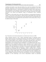
are analyzed as follows.
Figure 1 shows the measured transfer curves of an nMOSFET in 0.35-μm CMOS process at
different temperatures from –20 to 100°C. The drain-source voltage was set to 1 V. The
threshold voltage is about 0.5 V in this device. The subthreshold drain current I
DS
of a
MOSFET is an exponential function of the gate-source voltage V
GS
and the drain-source
voltage V
DS
and is given by
0
= exp 1 exp ,
GS TH DS
DS
TT
VV V
IKI
VV
η
⎛⎞
⎛⎞⎛⎞
−
−−
⎜⎟
⎜⎟⎜⎟
⎜⎟
⎝⎠⎝⎠
⎝⎠
(1)
2
0
=(1)
OX T
IC V
μη
−
0 0.2 0.4 0.6 0.8 1
10
-10
10
-8
10
-6
10
-4
V
GS
(V)
I
DS
(A)
20 C
100 C
Subthreshold region
V
GS
I
DS
10
-9
10
-7
10
-5
Fig. 1. Measured transfer curves of nMOSFET as a function of gate-source voltage V
GS
at
different temperatures.
CMOS Voltage and Current Reference Circuits consisting of Subthreshold MOSFETs
3
where K is the aspect ratio (=W/L) of the transistor, μ is the carrier mobility, C
OX
is the gate-
oxide capacitance, V
T
(=k
B
T/q) is the thermal voltage, k
B
is the Boltzmann constant, T is the
absolute temperature, and q is the elementary charge, V
TH
is the threshold voltage of a
MOSFET, and η is the subthreshold slope factor [3], [19]. For V
DS
> 0.1 V, current I
DS
is
independent of V
DS
and is given by
0
=exp .
GS TH
DS
T
VV
IKI
V
η
⎛⎞
−
⎜⎟
⎝⎠
(2)
The temperature dependence of the threshold voltage V
TH
and the mobility μ of MOSFET
can be given by
0
=,
TH TH
VV T
κ
−
(3)
00
()= ( )(/ )
m
TTTT
μμ
−
(4)
where μ(T
0
) is the carrier mobility at room temperature T
0
, m is the mobility temperature
exponent, V
TH0
is the threshold voltage at 0 K, and κ is the temperature coefficient of V
TH
[20].
The temperature coefficient (T.C.) of the subthreshold current with fixed gate-source voltage
is given by
1
=
DS
DS
dI
TC
IdT
2
2
11 1
=exp(()/)
exp(( )/ )
T
GS TH T
TGSTHT
ddV d
VV V
dT V dT V V V dT
μ
η
μη
++ −
−
2()/
=.
GS TH
T
mVVT
TV
κ
η
−−−
+ (5)
Process variations can be classified into two categories: i.e., within-die (WID) (intra-die)
variation and die-to-die (D2D) (inter-die) variation [21]-[23]. The WID variation is caused by
mismatches between transistor parameters within a chip and affects the relative accuracy of
the parameters. In contrast, the D2D variation affects the absolute accuracy of transistor
parameters between chips.
The process dependence of the subthreshold current can be expressed by
1
==.
DS DS DS TH
TH
DS DS TH T
III V
V
II V V
μ
μ
μμη
⎛⎞
Δ∂∂ ΔΔ
Δ+ Δ −
⎜⎟
∂∂
⎝⎠
(6)
The mobility variation Δμ is generally smaller than the threshold voltage variation ΔV
TH
, so
the current depends mainly on ΔV
TH
.
Figure 2 shows the simulated subthreshold current with fixed gate-source voltages, obtained
with a SPICE simulation with a set of 0.35-μm standard CMOS process. Current operating in
the strong inversion region is also plotted for comparison. Fixed gate-source voltages were
set to V
TH
–0.2 V (weak inversion), and V
TH
+0.2 V (strong inversion), respectively. Although
Solid State Circuits Technologies
4
I
DS
: Weak inversion (V
Bias
=V
TH
0.2)
I
DS
: Strong inversion (V
Bias
=V
TH
+
0.2)
3%/ C
T.C .
0.5%/ C
2.5%/mV
ΔI
DS
ΔV
TH
0.8%/mV
1
10
100
0.1
0.01
0 0.05 0.10.050.1
ΔV
TH
(V)
20 40 60 80200
Temperature ( C)
Current (I
DS
/ I
DS (27 C)
)
1
10
100
0.1
0.01
Current (I
DS
/ I
DS (Typ.)
)
I
DS
: Weak inversion
I
DS
: Strong inversion
V
Bias
I
DS
V
Bias
I
DS
(Subthreshold region)
I
DS
: Weak inversion
I
DS
: Strong inversion
(Subthreshold region)
Fig. 2. (A). Simulated drain currents as a function of temperature. Fixed gate biases were set
to V
TH
–0.2 V (weak inversion), and V
TH
+0.2 V (strong inversion). (B). Drain currents as a
function of D2D threshold voltage variation ΔV
TH
, as obtained from Monte Carlo simulation
of 300 runs.
the current in the strong inversion region has a small temperature dependence (0.5%/°C),
the subthreshold current has a large temperature dependence (3%/°C), as shown in Fig. 2-
(A). Figure 2-(B) shows the simulated subthreshold current as a function of the threshold
voltage variation ΔV
TH
, as obtained from Monte Carlo simulation of 300 runs, assuming
both die-to-die (D2D) variation (e.g., ΔV
TH
, Δμ, ΔT
OX
, ΔL, ΔW) and within die (WID)
variation (e.g., σ
V
TH
, σ
μ
, σ
T
OX
, σ
L
, σ
W
) in transistor parameters [21; 22; 23]. Each open circle and
square show I
DS
for a run. The subthreshold current depends strongly on the threshold
voltage variation (2.5%/mV) in comparison with the strong inversion current (0.8%/mV).
Therefore, the subthreshold current is strongly dependent on temperature and process
variations. In circuit designs, the process sensitivity of the subthreshold current has to be
reduced by using large-sized transistors [23] and various analog layout techniques [24]. On
the other hand, the exponential behavior and the high sensitivity to temperature of the
subthreshold current can be used to compensate for temperature variation of a constant
voltage, such as voltage reference circuits.
3. Voltage and current references based on bandgap reference circuits
Bandgap voltage reference circuits are widely used as voltage references. Figure 3 shows
conventional bandgap voltage reference circuits [5],[6]. The circuits generate reference
voltages independent of the process, supply voltage, and temperature, and consist of the
MOSFET circuits, substrate pnp bipolar transistors, and resistors. The operation principles
are as follows.
CMOS Voltage and Current Reference Circuits consisting of Subthreshold MOSFETs
5
M
1
M
2
R
4
V
REF
I
REF
Q
2
Q
1
M
1
M
2
V
REF
I
P
Q
2
Q
1
Q
3
I
REF
I
REF
I
P
I
P
(A) (B)
I
1
I
1
I
2
I
2
R
2
R
3
R
1
I
1
+
I
2
=
( )
I
1
+
I
2
=
( )
I
1
+
I
2
=
( )
R
2
R
1
Fig. 3. (A). Conventional bandgap voltage reference circuit [5]. (B) Sub-1-V output bandgap
voltage reference circuit [6] and current reference circuit [25].
3.1 Operation as voltage reference circuit
The collector current I
C
of the bipolar transistor is given by
=exp
BE
CS
T
V
IKI
V
⎛⎞
⎜⎟
⎝⎠
(7)
where K is the transistor size, I
S
is the saturation current, and V
BE
is the base-emitter voltage [5].
In the circuit in Fig. 3-(A), the operation current I
P
is determined by the bipolar transistors
Q
1
and Q
2
with different transistor sizes and the resistor R
1
, and is given by
12 21
11
ln( / )
== .
BE BE T
P
VV VKK
I
RR
−
(8)
The current I
P
is proportional to absolute temperature (PTAT). The resistor R
2
and the
transistor Q
3
accept the current through the current mirror circuit and produce the output
voltage, which is given by
2
323 21
1
== ln(/).
REF BE P BE T
R
VVIRV VKK
R
++ (9)
Equation (9) shows that V
REF
can be expressed as a sum of the base-emitter voltage and
thermal voltage scaled by the resistor ratio. Because V
BE
has a negative T.C. and V
T
has a
positive T.C., output voltage V
REF
with a zero T.C. can be obtained by adjusting the resistor
ratio. The reference voltage is based on the bandgap energy of silicon, which is about 1.25 V.
Banba et al. proposed a modified bandgap voltage reference circuit as shown in Fig. 3-(B).
The circuit generates sub-1-V reference voltage. The operation currents I
1
and I
2
are given by
12 21 1
12
11 2
ln( / )
= = , = .
BE BE T BE
VV VKK V
II
RR R
−
(10)
The resistor R
4
accepts the current I
REF
(=I
1
+I
2
) through a current mirror circuit and produces
output voltage, so the output voltage can be expressed as
Solid State Circuits Technologies
6
44
41 21
21
== ln(/).
REF REF BE T
RR
VIR V VKK
RR
+
(11)
Therefore, adjusting the resistor ratio, the circuit generates sub-1-V reference voltage that is
independent of temperature.
3.2 Operation as current reference circuit
The circuit as shown in Fig. 3-(B) can be used as a current reference generator [25]. The
temperature dependence of resistors is given by R = R
0
(1+
α
T), where R
0
is the resistance
value at absolute zero temperature, and
α
is the temperature coefficient of the resistor.
Because V
BE
and ΔV
BE
(=V
BE1
− V
BE2
) have a negative and a positive temperature dependence,
respectively, the temperature dependences can be expressed simply by V
BE
=V
BE0
(1 − AT)
and ΔV
BE
=BT, where A and B are the T.C. of V
BE
and ΔV
BE
, respectively, and V
BE0
is the
baseemitter voltage at absolute zero temperature. Therefore, the reference current
I
REF
(=I
1
+I
2
) is given by
10
12
1 2 01 02
(1 )
== =
(1 ) (1 )
BE BE BE
REF
VV BT V AT
III
RRR TR T
αα
Δ−
++ +
++
01
01 02
1
= ( )(1 ) (1 )(1 )
BE
V
BT T AT T
RR
α
α
−+ − −
01
01 02
1
() (1( )).
BE
V
BT A T
RR
α
≈+−+
(12)
The left and right terms in Eq. (12) have negative and positive temperature dependence,
respectively. Therefore, adjusting the appropriate resistor values, the circuit generates a
reference current that is independent of temperature.
These circuits generate stable reference voltages and currents. However, the power
dissipations of these circuits are too large (from 5 to 500 μW), so they need resistors with a
high resistance of several hundred megaohms to achieve low-current, sub-microwatt
operation. Such high resistance needs a large area to be implemented, and this makes
conventional bandgap references unsuitable for use in ultra-low-power LSIs.
4. Overview of low-power voltage reference circuits
To achieve ultra-low-power operation and small area, modified voltage reference circuits
without bipolar transistors have been reported (see [12]-[18]). These circuits consist of
CMOS circuits that operate in the strong inversion and the subthreshold regions of
MOSFET. The circuits generate a reference voltage that is independent of temperature and
supply voltage. The next sections provide an overview of the reported low-power voltage
reference circuits.
4.1 Voltage references based on ΔV
GS
Figure 4 shows voltage reference circuits based on the difference between the gate-source
voltages of (A) two nMOS transistors, and (B) nMOS and pMOS transistors as reported by
Song et al. [7] and Leung et al. [8], respectively. All MOSFETs operate in the strong inversion
region.
CMOS Voltage and Current Reference Circuits consisting of Subthreshold MOSFETs
7
(A)
M
N
V
REF
(B)
V
REF
I
B
I
B
2
M
1
M
2
M
P
R
1
R
2
Fig. 4. Voltage reference circuits based on difference between gate-source voltages of (A)
two nMOS transistors [7], and (B) nMOS and pMOS transistors [8].
The drain current I
DS
that operates in the strong inversion, saturation region can be
expressed as
2
=( )
2
DS GS TH
K
IVV
β
−
(13)
where K is the aspect ratio of the transistors, and
β
(= μC
OX
) is the current gain factor.
The circuit in Fig. 4-(A) consists of M
1
and M
2
with different threshold voltage devices. The
reference voltage is given by
12
=
REF GS GS
VVV−
01 02
12
211
=( ) ( )
B
TH TH
I
VTVT
KK
κκ
β
⎛⎞
−− −+ −
⎜⎟
⎜⎟
⎝⎠
01 02
.
TH TH
VV≈−
(14)
A low bias current I
B
is used so that the temperature dependence of
β
can be ignored.
Therefore, the reference voltage based on the difference between the threshold voltages can
be obtained. However, the circuit requires a multiple-threshold voltage process, and, to
cancel the temperature dependence of the reference voltage, the process must be controlled
carefully so that the temperature coefficients κ of the two threshold voltages have the same
value in each MOSFET.
Figure 4-(B) shows another voltage reference circuit based on the difference between the
gate-source voltages of nMOS and pMOS transistors using a standard CMOS process. The
reference voltage is given by
1
2
=1 .
REF GSN GSP
R
VVV
R
⎛⎞
+−
⎜⎟
⎝⎠
(15)
Therefore, adjusting the resistor ratio and the transistor sizes, the temperature dependence
of the threshold voltages can be canceled, while the temperature dependence of the
Solid State Circuits Technologies
8
mobilities can be canceled only at room temperature. Consequently, the T.C. of the output
voltage will be degraded for a wide temperature range. As reported in [8], a measured T.C.
of 36.9 ppm/°C and a power dissipation of 30 μW were obtained. However, the power
dissipation is still too large for use with sub-microwatt operation. To reduce the power
dissipation, the circuit requires resistors with high resistance.
4.2 Voltage references operating in the strong inversion region of MOSFETs
Vita et al. proposed a voltage reference circuit consisting of transistors M
3
–M
8
operating in
the strong inversion region, and M
1
and M
2
operating in the subthreshold region as shown
in Fig. 5-(A) [9]. In this circuit, the gate-source voltages for the four MOSFETs (M
1
through
M
4
) form a closed loop, so we find that V
GS3
+ V
GS1
= V
GS2
+ V
GS4
, i.e.,
21 4 3
ln( / )=2/ 2/ .
TBB
VKK IK IK
η
ββ
− (16)
Therefore, the bias current I
B
can be expressed by
2
3
22
2
4
21
34
=(/) .
ln
2
BT
K
K
IVKK
KK
β
η
⎛⎞
⎜⎟
⎜⎟
−
⎝⎠
(17)
Transistors M
5
–M
8
accept the current I
B
and generate the output voltage. Most of the bias
current I
B
must flow through M
7
and M
8
rather than through M
5
and M
6
to compensate for
the temperature dependence of the mobility μ. Therefore, the output voltage can be given by
6
857
5
87
21 1
== 1
B
REF GS GS GS TH
IK
VVVVV
K
KK
β
⎛⎞
⎛⎞
+− + + −
⎜⎟
⎜⎟
⎜⎟
⎜⎟
⎝⎠
⎝⎠
34
6
21
5
348 7
11
=ln(/) 1 .
TH T
KK
K
VVKK
K
KKK K
η
⎛⎞
⎛⎞
++−
⎜⎟
⎜⎟
⎜⎟
⎜⎟
−
⎝⎠
⎝⎠
(18)
V
REF
M
1
M
2
R
1
R
2
V
REF
M
1
M
2
M
3
M
4
M
5
M
6
M
7
M
8
(B)(A)
I
B
I
B
I
B
I
B
I
B
Fig. 5. Voltage reference circuit (A) operated in the strong inversion region [9], and (B) based
on peaking current mirror circuit [10].
CMOS Voltage and Current Reference Circuits consisting of Subthreshold MOSFETs
9
Because V
TH
in Eq. (3) has a negative T.C. and V
T
has a positive T.C., output voltage V
REF
with a zero T.C. can be obtained by adjusting the size of the transistors.
As reported in [9], a measured T.C. of 12 ppm/°C and a power dissipation of 0.12 μW were
obtained. Although the operation current of the circuit is on the order of nanoamperes,
transistors M
3
–M
8
operate in the strong inversion, saturation region. So, designs with careful
transistor sizing are required for operation in each of the regions in MOSFETs.
4.3 Voltage references operating in the subthreshold region of MOSFETs
Cheng et al. developed a voltage reference using a peaking current mirror circuit as shown
in Fig. 5-(B) [10]. All MOSFETs operate in the subthreshold region. The circuit forms a
closed loop, i.e., V
GS1
= V
GS2
− I
B
R
2
, so the bias currents I
B
can be expressed by
21 12
22
ln( / )
== .
GS GS T
B
VV VKK
I
RR
η
−
(19)
The output voltage is given by
21
=
REF GS B
VVIR
+
1
212
2
=ln(/).
GS T
R
VVKK
R
η
+ (20)
Because V
GS
and V
T
have a negative and a positive T.C., respectively, output voltage V
REF
with a zero T.C. can be obtained by adjusting the resistor ratio. As reported in [10], a
measured
temperature coefficient of 62 ppm/°C and a power dissipation of 4.6 μW were
obtained.
Huang et al. proposed a voltage reference circuit based on subthreshold MOSFETs [11] as
shown in Fig. 6. The bias currents I
1
and I
2
are given by
89 98 35
121
22 16
ln( / )
= = , = .
GS GS T GS
VV VKK V K
III
RR RK
η
−
− (21)
Therefore, the output voltage can be expressed by
10 11
123
72
=
REF
KK
VIIR
KK
⎛⎞
+
⎜⎟
⎝⎠
11 3 10 11 5 3
398
21 7 26 2
=ln(/).
GS T
KR K KK R
VVKK
KR K KK R
η
⎛⎞
+−
⎜⎟
⎝⎠
(22)
Because V
GS
has a negative T.C. and V
T
has a positive T.C., output voltage V
REF
with a zero
T.C. can be obtained by adjusting the resistor ratio and the transistor sizes. As reported in
[11], a measured temperature coefficient of 271 ppm/°C and a power dissipation of 3.3 μW
were obtained. In the circuits as shown in Figs. 5-(B) and 6, however, the power dissipations
are still large. To achieve sub-microwatt operation, these circuits require resistors with a
high resistance of several hundred megaohms.
Solid State Circuits Technologies
10
M
3
V
REF
M
2
M
1
M
5
M
6
M
7
M
8
M
9
M
10
M
11
M
4
I
1
I
1
I
1
I
2
R
1
R
2
R
3
K
6
K
5
I
1
K
7
K
10
I
2
K
2
K
11
Fig. 6. Voltage reference circuit operated in the subthreshold region [11].
V
REF
M
7
M
8
M
3
M
4
M
9
M
5
M
6
M
1
M
2
M
10
I
2
I
2
I
1
I
1
I
2
Fig. 7. Voltage reference circuit operated in the strong inversion and subthreshold regions
using high-V
TH
devices [12].
Vita et al. proposed a voltage reference circuit using two different threshold voltage devices
as shown in Fig. 7 [12]. Transistors M
1
and M
3
with high-V
TH
devices are operated in the
subthreshold region, and M
2
and M
4
are operated in the strong inversion region. From V
GS1
=
V
GS2
and V
GS3
= V
GS4
, i.e.,
12
10 2
2
ln =
HIGH
TH T TH
II
VV V
KI K
η
β
⎛⎞
++
⎜⎟
⎝⎠
12
30 4
2
ln = .
HIGH
TH T TH
II
VV V
KI K
η
β
⎛⎞
++
⎜⎟
⎝⎠
(23)
Therefore, the output load current I
2
can be expressed as
CMOS Voltage and Current Reference Circuits consisting of Subthreshold MOSFETs
11
22
2
4
231
2
42
=(/).
ln
2( / 1)
T
K
IVKK
KK
β
η
−
(24)
Transistor M
10
accepts the current I
2
, and the output voltage can be given by
2
10
2
=
REF TH
I
VV
K
β
+
410
31
42
/
=ln(/) .
/1
TH T
KK
VVKK
KK
η
+
−
(25)
Because V
TH
has a negative T.C. and V
T
has a positive T.C., output voltage V
REF
with a zero
T.C. can be obtained by adjusting the size of the transistors.
As reported in [12], a measured T.C. of 10 ppm/°C and a power dissipation of 0.036 μW
were obtained. However, the circuit requires a high-V
TH
devices.
4.4 Voltage references consisting of subthreshold MOSFETs
Figure 8 shows our voltage reference circuit, which consists of a current source subcircuit
and a bias-voltage subcircuit [13]. The current source subcircuit is a modified
β
multiplier
self-biasing circuit that uses a MOS resistor M
R1
instead of ordinary resistors. All the
MOSFETs except for M
R1
operate in the subthreshold region. MOS resistor M
R1
is operated in
a strong-inversion, deep-triode region. The circuit generates two voltages, one with a
negative T.C. and one with a positive T.C., and combines them to produce a constant
voltage with a zero T.C
In the current source subcircuit, the current I
P
is determined by two transistors M
1
and M
2
,
and the MOS resistor M
R1
. The current I
P
is given by
1
1
=
DSR
P
R
M
V
I
R
121
=( )ln(/).
ROXREFTHT
KCV V V KK
μ
η
−
(26)
In the bias-voltage subcircuit, the gate-source voltages (V
GS3
through V
GS7
) of the transistors
form a closed loop [26], and the currents in M
4
and M
6
are 3I
P
and 2I
P
. Therefore, we find that
output voltage V
REF
of the circuit is given by
43657
=
REFGSGSGSGSGS
VVVVVV−+−+
35
4
67
2
=ln
GS T
KK
VV
KK
η
⎛⎞
+
⎜⎟
⎝⎠
35
40 6 7
32
=ln ln
P
TH T T
IKK
VV V
KI KK
ηη
⎛⎞ ⎛ ⎞
++
⎜⎟ ⎜ ⎟
⎝⎠ ⎝ ⎠
(27)
where we assume that the mismatch between the threshold voltages of the transistors can be
ignored. Equation (27) shows that V
REF
can be expressed as a sum of the gate-source voltage
V
GS4
and thermal voltage V
T
scaled by the transistor sizes. Because V
TH
in Eq. (3) has a
Solid State Circuits Technologies
12
V
REF
M
1
M
2
M
3
M
4
M
5
M
6
M
7
M
R1
I
P
I
P
I
P
I
P
I
P
Current source subcircuit
Bias voltage subcircuit
Fig. 8. Schematic of our voltage reference circuit [13]. All MOSFETs are operated in
subthreshold region, except for MOS resistor M
R1
, which is operated in strong-inversion,
triode region.
negative T.C. and V
T
has a positive T.C., output voltage V
REF
with a zero T.C. can be
obtained by adjusting the size of the transistors.
On the condition that V
REF
− V
TH0
κT and ηV
T
κT, the T.C. of V
REF
can be rewritten as
135 2
467 1
6
=ln ln.
(1)
REF B R
B
q
dV k K K K K
dT q k K K K K
ηκ
η
κ
η
⎧
⎫
⎛⎞
⎪
⎪
−+
⎨
⎬
⎜⎟
−
⎪
⎪
⎝⎠
⎩⎭
(28)
Therefore, a zero T.C. voltage can be obtained by setting the aspect ratios K
i
in accordance
with T.C.=0 (i.e., Eq. (28)=0). From Eqs. (27) and (28), we find that
0
=.
REF TH
VV
(29)
This shows that the circuit generates a voltage equal to the threshold voltage of MOSFETs at 0 K.
Using Eqs. (26) and (29), we can express current I
P
as
2
1
1
=ln.
PROX T
K
IKCTV
K
μκη
⎛⎞
⎜⎟
⎝⎠
(30)
The current is determined only by the aspect ratios (K
1
, K
2
, and K
R1
) and the temperature
coefficient (κ) of the threshold voltage of MOSFETs, and it is independent of the threshold
voltage V
TH
, so the current I
P
is less dependent on process variations as shown in the next
section. The T.C. of the current can be given by
1111 2
==.
PT
PT
dI d dT dV m
IdT dT TdT VdT T
μ
μ
−
++
(31)
The value of m is about 1.5 in standard CMOS process technologies, so current I
P
has a
positive T.C. and increases with temperature.
CMOS Voltage and Current Reference Circuits consisting of Subthreshold MOSFETs
13
0
10
20
30
40
Occurrences
50
60
70
0.7
0.8
0.9
1.0
V
REF
(V)
0 0.05 0.10.050.1
ΔV
TH
(V)
0.6 0.7 0.8 0.9 1.0
V
REF
(V)
(A) (B)
ΔV
REF
/ΔV
TH
~
~
1
1.1
μ = 0.84 V
σ = 0.06 V
σ/μ = 7 %
Fig. 9. (A). Average output voltage as a function of D2D variation ΔV
TH
of threshold voltage,
as obtained from Monte Carlo simulation of 300 runs. Output voltage shows a linear
dependence on threshold voltage (Δ
REF
V /ΔV
TH
≈1). (B). Distribution of output voltage, as
obtained from Monte Carlo simulation.
4.4.1 Simulation and experimental results
We demonstrated the operation of our circuit with the aid of a SPICE simulation using a set
of 0.35-
μm standard CMOS parameters and assuming a 1.5-V power supply. To study the
dependence of the output voltage on process variations, we performed Monte Carlo
simulations assuming both D2D variation (e.g., Δ
V
TH
, Δμ, ΔT
OX
, ΔL, ΔW) and WID variation
(e.g.,
σ
V
TH
, σ
μ
, σ
T
OX
, σ
L
, σ
W
) in transistor parameters.
The results for 300 runs are depicted in Fig. 9. Figure 9-(A) shows the dispersion of
V
REF
from the average value (
REF
V ) of V
REF
from –20 to 80°C as a function of D2D threshold-
voltage variation Δ
V
TH
. Each open circle shows
REF
V
for a run. As expected from Eq. (29),
V
REF
varies significantly with each run in a range from 0.75 to 0.95 V; this reflects the
variation in transistor parameters for each run. The value of
REF
V
depends linearly on ΔV
TH
because the circuit produces the voltage equal to the 0-K threshold voltage of MOSFETs.
Figure 9-(B) shows the distribution of
REF
V . The average of
REF
V
was 840 mV, and the
standard deviation was 60 mV. The coefficient of variation (
σ/μ) was 7%, including D2D
and WID variations.
We fabricated a prototype chip, using a 0.35-
μm, 2-poly, 4-metal standard CMOS process.
Figure 10-(A) shows measured output voltage
V
REF
as a function of temperature with supply
voltage
V
DD
as a parameter. Almost constant voltage was achieved. The average of the
output voltage was 745 mV. The temperature variation was 0.48 mV in a temperature range
from –20 to 80°C, so the temperature coefficient was 7 ppm/°C. The line regulation was 20
ppm/V in the supply range of 1.4 to 3 V.
Figure 10-(B) shows measured current
I
P
as a function of temperature with power supply
voltage as a parameter. The current
I
P
was about 36 nA at room temperature and reached the
maximum of 39 nA at 80°C. The power dissipation of the circuit with a 1.5-V power supply
was 0.32
μW at room temperature and varied from 0.28 to 0.35 μW at temperatures from –20
to 80°C. The temperature variation of the power dissipation was 0.2%/°C.
Solid State Circuits Technologies
14
I
P
(nA)
30
32
34
36
38
40
20 40 60 80200
V
DD
= 1.4 V
V
DD
= 1.5 V
V
DD
= 2.0 V
V
DD
= 2.5 V
V
DD
= 3.0 V
20 40 60 80200
V
DD
= 1.4 V
V
DD
= 1.5 V
V
DD
= 2.0 V
V
DD
= 2.5 V
V
DD
= 3.0 V
744.8
745.0
745.2
745.4
745.6
V
REF
(mV)
(A) (B)
Temperature ( C)
Temperature ( C)
Fig. 10. (A). Measured output voltage
V
REF
as a function of temperature, with various supply
voltages. Temperature coefficient was 7 ppm/°C and the supply regulation was 20 ppm/V.
(B). Measured current
I
P
as a function of temperature for different supply voltages.
Table I summarizes the characteristics of our circuit [13] in comparison with other low-
power CMOS voltage references reported in [8]-[12]. Our device is comparable to other
circuits in power dissipation, PSRR, and chip area, and it is superior to others in T.C. and
line sensitivity. Our circuit is therefore useful as a voltage reference for power-aware LSIs.
Table 1. Comparison of reported low-power CMOS voltage reference circuits
CMOS Voltage and Current Reference Circuits consisting of Subthreshold MOSFETs
15
4.4.2 Discussion
Our circuit has several possible applications. The output voltage of our circuit can be used
as a monitor signal for the D2D process variation in MOSFET threshold voltage because the
output voltage is equal to the 0-K threshold voltage of MOSFETs in an LSI chip and is
linearly dependent on the
V
TH
variation, as shown in Fig. 9-(A). This output voltage can be
used to compensate for the threshold voltage variation in LSI chips. For example, consider
the application to a reference current source. The process variation of the current
I
P
flowing
in the circuit as shown in Fig. 8 (see Eq. (30)) can be expressed as
1
=
PPP P
OX
PP OX
III I
C
II C
μ
κ
μκ
⎛⎞
Δ∂∂ ∂
Δ
+Δ+Δ
⎜⎟
∂∂ ∂
⎝⎠
=.
OX
OX
C
C
μ
κ
μ
κ
Δ
ΔΔ
++ (32)
The current is independent of the threshold voltage variation. Although the current depends
on the variation of the mobility Δ
μ/μ, gate-oxide capacitance ΔC
OX
/C
OX
, and the
temperature coefficient of the threshold voltage Δ
κ/κ, these variations are far smaller than
the threshold voltage variation.
This way, the circuit can be used as an elementary circuit block for on-chip D2D process
compensation systems, such as process- and temperature-compensated current references
[27].
5. Overview of low-power current reference circuits
Current references with nanoampere-order currents are required to ensure circuit operation
that is stable and highly precise, because power dissipation and performance of circuits are
determined mainly by their bias currents. Nanoampere-current references for ultra-low-
power LSIs have been reported in several papers [13]-[15]. The next sections provide an
overview of the reported nanoampere current reference circuits.
5.1 Current references based on weak and strong inversion regions of MOSFETs
Sansen et al. developed a current reference circuit without resistors as shown in Fig. 11 [14].
Transistors M
2
–M
11
operate in the subthreshold region, and M
1
and M
12
operate in the strong
inversion region. The gate-source voltages of M
1
–M
12
form a closed loop, so we find that
1 12101189674523
=.
GS GS GS GS GS GS GS GS GS GS GS GS
V VVVVVVVVVVV+−+−+−+−+− (33)
Assuming that the body effects of M
2
–M
10
are ignored, the output current I
REF
is given by
22
2
11 9 7 5 3 1 12
10 8 6 4 2 12 1
= 120 .
ln
2
REF T
KKKKK KK
IV
KKKKK K K
β
η
⎛⎞
⎛⎞
⋅
⎜⎟
⎜⎟
−
⎝⎠
⎝⎠
(34)
The T.C. of the reference current is given by
2
2
1112
= = = .
REF T
REF T
dI d dV m
TC
IdT dTVdT T
μ
μ
−
+ (35)